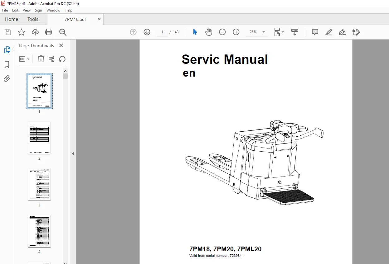
Toyota Forklift 7PM18 7PM20 7PML20 Service Manual SN 723984 – PDF DOWNLOAD
$27.95
Toyota Forklift 7PM18 7PM20 7PML20 Service Manual SN 723984 – PDF DOWNLOAD
Description
Toyota Forklift 7PM18 7PM20 7PML20 Service Manual SN 723984 – PDF DOWNLOAD
FILE DETAILS:
Toyota Forklift 7PM18 7PM20 7PML20 Service Manual SN 723984 – PDF DOWNLOAD
Language : English
Pages : 148
Downloadable : Yes
File Type : PDF
DESCRIPTION:
Toyota Forklift 7PM18 7PM20 7PML20 Service Manual SN 723984 – PDF DOWNLOAD
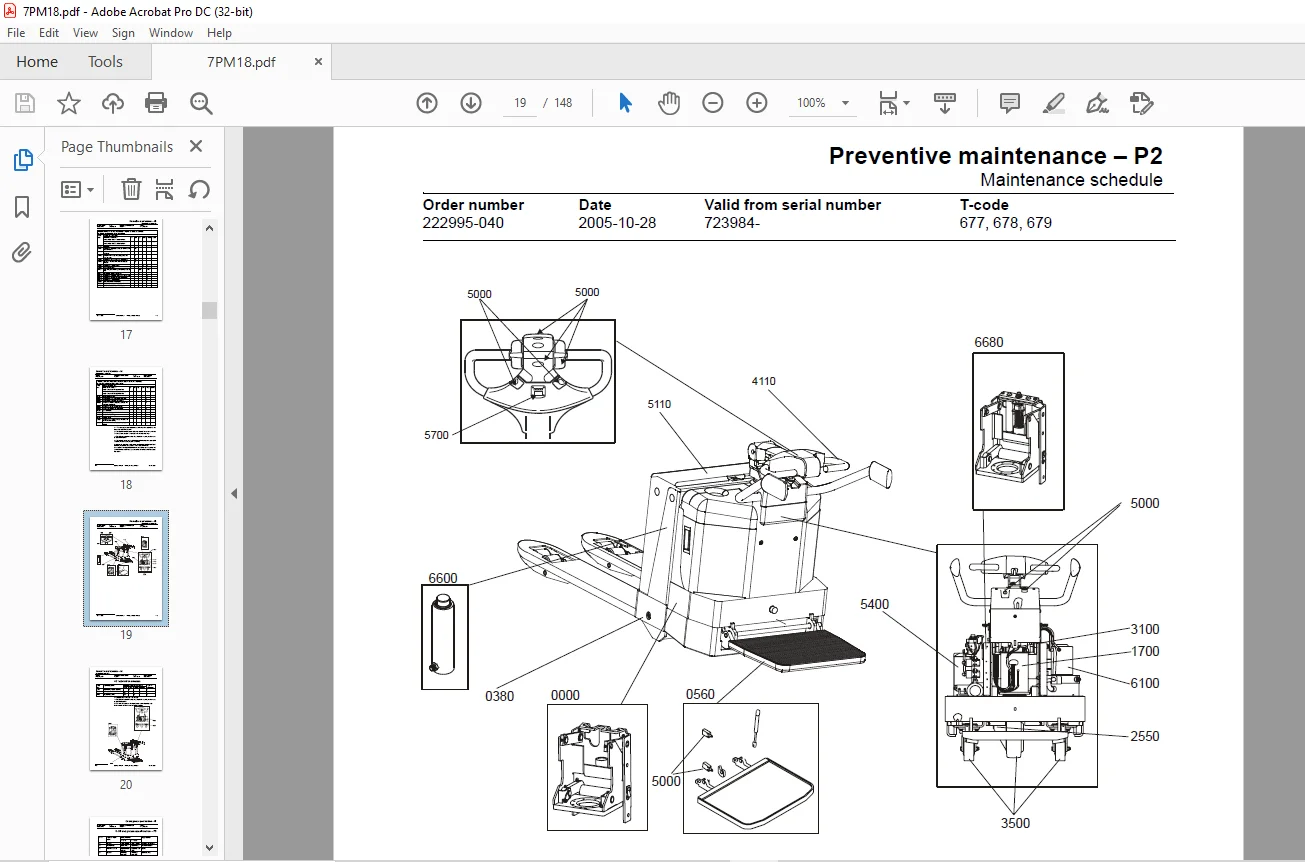
3- Introduction Maintenance – P1:
- All points in the service program should be carried out to attain the highest safety and the least possible downtime. The service intervals are only a guide and do not need to be followed to the letter. The operator may adapt them to local conditions, but it is important that the intervals comply with TOYOTA’s minimum requirements.
- The service intervals are based on the running times and can be adapted to most normal 8 hour shifts. The service interval may be shortened if the truck is used more frequently or in more demanding situations, e.g cold store, dusty or corrosive situations. The following running times have been used when calculating the intervals:
-Day time:08.00-17.00 (20 hr./week)
-2-shifts:06.00-14.00, 14.00-22.00 (40 hr./week)
-3-shifts:06.00-14.00, 14.00-22.00,22.00-06.00 (60 hr./week)
Ensure the truck is given a regular maintenance service after every 500 driving hours. The truck’s safety, efficiency and service life is dependent on the service and maintenance it is given.
Only use TOYOTA approved spare parts when service and repair work are carried out.
3.1 Safety regulations with maintenance work:
Only personnel that have been trained in the service and repair of this type of truck are authorised to carry out service and repair work.
•Do not carry out any maintenance work on the truck unless you have the correct training and knowledge to do so
•Keep the area where you carry out the service clean. Oil or water makes the floor slippery
•Never wear loose objects or jewellery when working on the truck
IMAGES PREVIEW OF THE MANUAL:
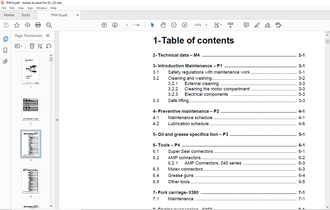
TABLE OF CONTENTS:
Toyota Forklift 7PM18 7PM20 7PML20 Service Manual SN 723984 – PDF DOWNLOAD
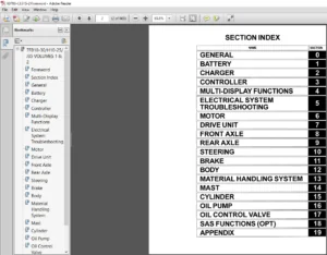
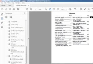
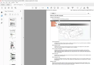
1- Table of contents......................................................................  3
2- Technical data - M4....................................................................  7
3- Introduction Maintenance - P1.......................................................... 11
	3.1 Safety regulations with maintenance work.......................................... 11
	3.2 Cleaning and washing.............................................................. 12
		3.2.1 External cleaning........................................................... 13
		3.2.2 Cleaning the motor compartment.............................................. 13
		3.2.3 Electrical components....................................................... 13
	3.3 Safe lifting...................................................................... 13
4- Preventive maintenance - P2............................................................ 15
	4.1 Maintenance schedule.............................................................. 15
	4.2 Lubrication schedule.............................................................. 20
5- Oil and grease specifica tion - P3..................................................... 21
6- Tools - P4............................................................................. 23
	6.1 Super Seal connectors............................................................. 23
	6.2 AMP connectors.................................................................... 24
		6.2.1 AMP Connectors, 040 series.................................................. 25
	6.3 Molex connectors.................................................................. 25
	6.4 Grease guns....................................................................... 26
	6.5 Other tools....................................................................... 27
7- Fork carriage- 0380.................................................................... 29
	7.1 Maintenance....................................................................... 29
8- Engine suspension- 0450................................................................ 31
	8.1 Component parts................................................................... 31
		8.1.1 Component List.............................................................. 32
9- Electric drive motor - 1760............................................................ 33
	9.1 Component parts................................................................... 33
		9.1.1 Dismantling/assembling of motor from truck.................................. 34
		9.1.2 Assembling.................................................................. 35
	9.2 Service/Repairs................................................................... 35
		9.2.1 Dismantling of motor........................................................ 35
		9.2.2 Assembling of motor......................................................... 36
		9.2.3 Cleaning.................................................................... 36
	9.3 Technical data.................................................................... 37
10- Mechanical drive gear unit - 2550..................................................... 39
	10.1 Component parts.................................................................. 40
		10.1.1 Technical data............................................................. 41
	10.2 Leakage from top cover........................................................... 42
		Dismantling....................................................................... 42
		Assembling........................................................................ 42
	10.3 Changing of the drive shaft’s sealing ring....................................... 42
		Dismantling....................................................................... 42
		Assembling........................................................................ 43
11- Electro magnetic brake - 3370......................................................... 45
	11.1 Main components.................................................................. 45
	11.2 Maintenance...................................................................... 46
		11.2.1 Exchange of brake disc..................................................... 46
12- Electro magnetic brake - 3370......................................................... 47
	12.1 Main components.................................................................. 47
	12.2 Maintenance...................................................................... 48
		12.2.1 Basic Adjustment of gap.................................................... 48
			Adjustment:................................................................... 48
		12.2.2 Exchange of brake disc..................................................... 48
13- Steering system - 4000................................................................ 49
	13.1 Component parts, tiller arm...................................................... 49
	13.2 Adjustments...................................................................... 50
		13.2.1 Adjusting of brake microswitch............................................. 50
	13.3 Tiller arm handle................................................................ 51
		13.3.1 Dismantling/Assembling..................................................... 52
			Change from ignition key to keyboard (2)...................................... 53
			Change from keyboard to ignition key (2)...................................... 53
			Changing of signal button/switch (9, 10)...................................... 53
			Changing of lift/lowering button (13)......................................... 54
			Changing of pushbutton (16)................................................... 54
14- Electrical System - 5000.............................................................. 55
	14.1 Electrical components............................................................ 55
	14.2 Symbol List and Wiring Diagram................................................... 57
		14.2.1 Wiring diagram 7PM18, 7PM20, 7PML20-6...................................... 59
		14.2.2 Wiring diagram 7PML20-8.................................................... 65
	14.3 Operating description............................................................ 76
		14.3.1 Starting truck............................................................. 76
		14.3.2 Driving speed £ 6 km/h..................................................... 76
		14.3.3 Braking in neutral mode.................................................... 76
		14.3.4 Braking in neutral mode on a slope......................................... 76
		14.3.5 Braking.................................................................... 77
		14.3.6 Lifting the forks.......................................................... 77
		14.3.7 Lowering the forks......................................................... 77
		14.3.8 Horn....................................................................... 77
	14.4 Hour meter....................................................................... 77
	14.5 Error codes...................................................................... 77
	14.6 Parameters....................................................................... 88
		14.6.1 Operator parameters........................................................ 89
		14.6.2 Parameter description...................................................... 89
			Parameter 1................................................................... 89
			Parameter 2................................................................... 89
			Parameter 3................................................................... 90
			Parameter 4................................................................... 90
			Parameter 5................................................................... 90
		14.6.3 Service parameters......................................................... 90
		14.6.4 Parameter description...................................................... 92
			Parameter 10.................................................................. 92
			Parameter 14.................................................................. 92
			Parameter 15 - Non-configurable option........................................ 92
			Parameter 16 - Configurable option #1......................................... 92
			Parameter 17 - Configurable option #2......................................... 92
			Parameter 18 - Configurable option #3......................................... 92
			Parameter 19 - Configurable option #4......................................... 92
			Option parameters............................................................. 93
			General....................................................................... 93
			Parameter #15 Non-configurable options........................................ 93
			Changing non-configurable options............................................. 93
			Parameter #16 to 19 configurable optional functions........................... 94
			Changing configurable optional functions...................................... 95
			Parameter 20.................................................................. 99
			Parameter 21.................................................................. 99
			Recommendation on parameter setting for freely ventilated batteries...........100
			Instructions for verifying parameter setting..................................101
			Recommendation on parameter setting for valve- controlled batteries (VRLA)....102
			Instructions for verifying parameter setting..................................103
			Parameter 22..................................................................103
			Parameter 25..................................................................103
			Parameter 28..................................................................103
			Parameter 39..................................................................103
			Login method and driver parameter access......................................104
			Expanded keypad - General.....................................................104
			Expanded keypad - Programming.................................................104
			Service indication............................................................106
	14.7 Part number......................................................................108
	14.8 Transistor panel.................................................................109
		14.8.1 General....................................................................109
	14.9 Troubleshooting..................................................................110
		14.9.1 Error codes and troubleshooting............................................110
		14.9.2 Reset error................................................................111
		14.9.3 Safety.....................................................................111
	14.10 Technical specifications - Curtis 1243..........................................112
15- Hydraulic/Pneumatic - 6000............................................................113
	15.1 General..........................................................................113
	15.2 Hydraulic chart and list of symbols..............................................113
		15.2.1 List of Symbols............................................................113
	15.3 Adjustments 7PM18................................................................114
		15.3.1 Adjusting the pressure limit valve.........................................114
		15.3.2 Tools......................................................................115
	15.4 Adjustments 7PM20................................................................116
		15.4.1 Adjusting the pressure limit valve.........................................116
	15.5 Hydraulic chart and list of symbols..............................................117
		15.5.1 List of Symbols............................................................117
	15.6 Adjusting the pressure limit valve...............................................118
16- PowerTrak cylinder - 6680.............................................................119
	16.1 Component parts..................................................................119
	16.2 Dismantling of PowerTrak cylinder................................................120
17- Battery charger (Inbuilt) - 8340......................................................121
	17.1 General..........................................................................121
	17.2 Charging.........................................................................121
	17.3 Troubleshooting and service......................................................121
	17.4 Technical data...................................................................122
	17.5 Charging settings................................................................122
		17.5.1 Freely ventilated batteries................................................122
		17.5.2 Valve regulated batteries..................................................123
18- Control/computer equipment - 8700.....................................................125
	18.1 General..........................................................................125
	18.2 Connection.......................................................................125
	18.3 Layout...........................................................................126
		18.3.1 Main program screen........................................................126
		18.3.2 Nodes......................................................................126
		18.3.3 Icons......................................................................127
		18.3.4 Tool buttons and menu bar..................................................128
		18.3.5 Information window.........................................................128
		18.3.6 Status bar.................................................................128
	18.4 Connection function..............................................................128
	18.5 Disconnection function...........................................................129
	18.6 Downloading program function.....................................................129
		18.6.1 Normal downloading (truck with key)........................................129
		18.6.2 Normal downloading (truck with keypad).....................................130
		18.6.3 Emergency downloading (truck with keypad)..................................130
		18.6.4 Downloading in old versions of logic card..................................130
		18.6.5 Emergency downloading (truck with keypad)..................................131
	18.7 Truck report function............................................................132
	18.8 Parameters function..............................................................133
	18.9 Diagnostics function.............................................................133
		18.9.1 Representation of signal colours...........................................134
		18.9.2 “Tiller arm” tab...........................................................134
		18.9.3 “Drive Controller” tab (transistor regulator - travel).....................135
		18.9.4 “Pump controller” tab (transistor regulator - pump)........................136
		18.9.5 “EPS” steering servo tab...................................................137
	18.10 Other menu functions............................................................138
		18.10.1 Save to file..............................................................138
		18.10.2 Download from file........................................................138
		18.10.3 Reset CAN adapter.........................................................138
		18.10.4 Delete error code log.....................................................138
		18.10.5 Reset hour meter..........................................................138
		18.10.6 Read error code log.......................................................138
		18.10.7 Adjust date and time......................................................139
		18.10.8 Adjusting the hour meter on older cards...................................139
		18.10.9 Help......................................................................139
			About the TruckCom application................................................139
		18.10.10 Exit.....................................................................139
	18.11 Specifications..................................................................139
	18.12 Installation....................................................................140
		18.12.1 Installation on a PC with Windows® 95/98..................................140
		18.12.2 Installation on a PC with Windows XP/ 2000................................140
		18.12.3 Installation on a PC with Windows NT......................................145
		18.12.4 In case of communication problems with CAN................................145
		18.12.5 To uninstall..............................................................146
Customer Support: [email protected]
PLEASE NOTE:
- This is the same manual used by the dealers to diagnose and troubleshoot your vehicle
- You will be directed to the download page as soon as the purchase is completed. The whole payment and downloading process will take anywhere between 2-5 minutes
- Need any other service / repair / parts manual, please feel free to contact [email protected] . We still have 50,000 manuals unlisted
S.V