TOYOTA Forklift 7SLL12.5 7SLL12.5F 7SLL16 7SLL16F Service Manual PDF
$28.95
TOYOTA Forklift 7SLL12.5 7SLL12.5F 7SLL16 7SLL16F Service Manual – PDF DOWNLOAD
Valid from serial number: 711956-
Order number: 222641-040
Description
TOYOTA Forklift 7SLL12.5 7SLL12.5F 7SLL16 7SLL16F Service Manual – PDF DOWNLOAD
FILE DETAILS:
TOYOTA Forklift 7SLL12.5 7SLL12.5F 7SLL16 7SLL16F Service Manual – PDF DOWNLOAD
Language : English
Pages : 202
Downloadable : Yes
File Type : PDF
IMAGES PREVIEW OF THE MANUAL:
TABLE OF CONTENTS:
TOYOTA Forklift 7SLL12.5 7SLL12.5F 7SLL16 7SLL16F Service Manual – PDF DOWNLOAD
Valid from serial number: 711956-
Order number: 222641-040
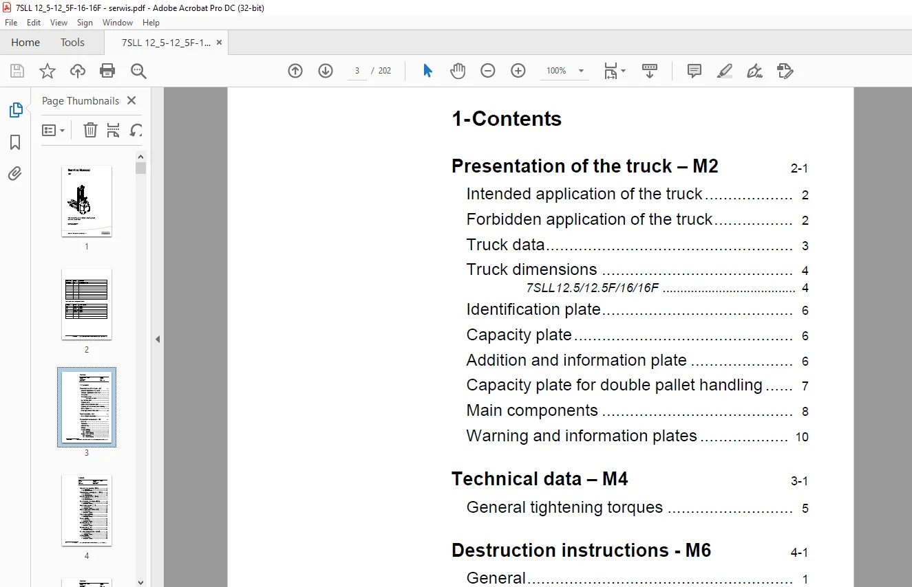
1- Contents 3
2- Presentation of the truck – M2 13
21 Intended application of the truck 14
22 Forbidden application of the truck 14
23 Truck data 15
24 Truck dimensions 16
7SLL125/125F/16/16F 16
25 Identification plate 18
26 Capacity plate 18
27 Addition and information plate 18
28 Capacity plate for double pallet handling 19
29 Main components 20
210 Warning and information plates 22
3- Technical data – M4 25
31 General tightening torques 29
4- Destruction instructions – M6 31
41 General 31
42 Procedure 31
43 Abbreviations 32
44 Sorting 32
45 Chassis (0300) 33
451 Dismantling 33
452 Material handling 33
46 Hoods, covers (0340) 34
461 Dismantling 34
462 Material handling 34
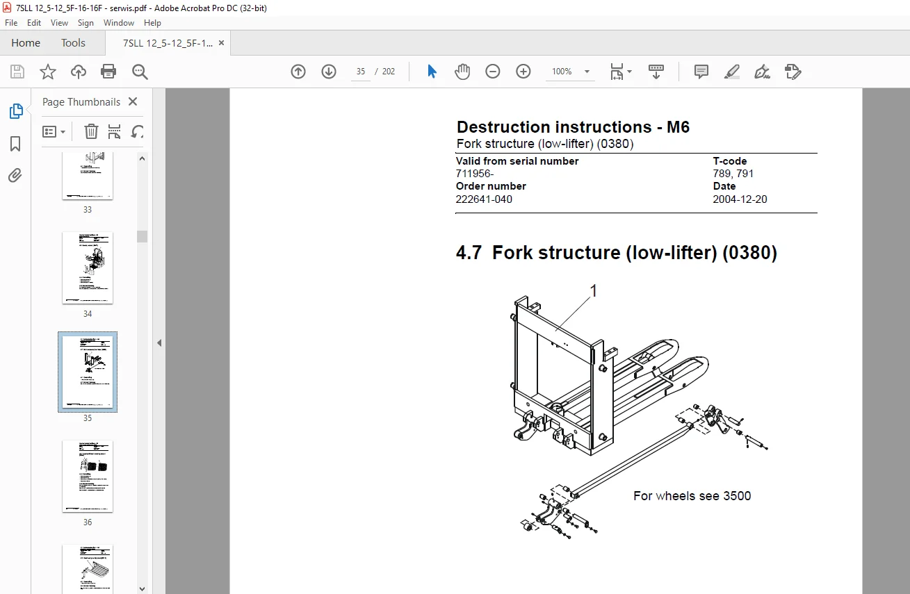
47 Fork structure (low-lifter) (0380) 35
471 Dismantling 35
472 Material handling 35
48 Travel platform including mount (0560) 36
481 Dismantling 36
482 Material handling 36
49 Overhead guard (option) (0810) 37
491 Dismantling 37
492 Material handling 37
410 Operator protective device (0840) 38
4101 Dismantling 38
4102 Material handling 38
411 Electric pump motor (1710) 39
4111 Dismantling 39
4112 Material handling 39
412 Electric travel drive motor (1760) 40
4121 Dismantling 40
4122 Material handling 40
413 Drive unit/gear (2550) 41
4131 Dismantling 41
4132 Material handling 41
414 Wheels (3500) 42
4141 Dismantling 42
4142 Material handling 42
415 Steering arm (4110) 43
4151 Dismantling 43
4152 Material handling 43
416 Steering arm (4110) 44
4161 Dismantling 44
4162 Material handling 44
417 General electric equipment (5100) 45
4171 Dismantling 45
4172 Material handling 45
418 Cabling (5590) 46
4181 Dismantling 46
4182 Material handling 46
419 Steering and protective electronics (5700) 47
4191 Dismantling 47
4192 Material handling 47
420 Lift/lowering sensor (5820) and safety sensor (5830) 48
4201 Dismantling 48
4202 Material handling 48
421 Hydraulic unit (6100) 49
4211 Dismantling 49
4212 Material handling 49
422 Main mast (7100) 50
4221 Dismantling 50
4222 Material handling 50
423 Chassis-mounted hydraulic oil lines (6230) (and main lift cylinder (6610) ) 51
4231 Dismantling 51
4232 Material handling 51
424 Battery charger connector (9380) 52
4241 Dismantling 52
4242 Material handling 52
5- Installation and maintenance instructions – P1 53
51 Truck installation 53
511 Lifting the truck 53
512 Battery installation 54
513 Putting into service 54
52 Introduction, maintenance 56
521 Safety rules during maintenance work 56
53 Cleaning and washing 58
531 External cleaning 58
532 Cleaning the motor compartment 58
533 Electric components 58
54 Safe lifting 59
6- Maintenance schedule – P2 61
61 Lubrication chart 67
7- Oil and grease specification – P3 69
8- Tools – P4 71
81 Super Seal connectors 71
82 AMP connectors 72
821 AMP Connectors, 040 series 73
83 Molex connectors 73
84 Other tools 74
9- Electric drive motor – 1760 75
91 Included components 75
92 Disassembly/assembly of the truck motor 77
921 Disassembly 77
922 Assembly 77
93 Service/repairs 78
931 Disassembly of the motor 78
932 Motor installation 79
933 Cleaning 79
94 Technical data 80
10- Drive unit/gear – 2550 81
101 Included components 82
1011 Technical data 83
102 Leakage from top cover 83
103 Replacing the drive axle jointing ring 83
1031 Disassembly 84
1032 Assembly 84
11- Electromagnetic brake – 3370 85
111 Main components of the brake 85
112 Maintenance 86
1121 Basic adjustment of the play 86
1122 Brake disc replacement 87
12- Electrical systems – 5000 89
121 Electrical equipment overview 89
122 Equipment list and electrical diagram 91
1221 Electrical wiring diagram 1 of 15 95
1222 Electrical wiring diagram 2 of 15 96
1223 Electrical wiring diagram 3 of 15 97
1224 Electrical wiring diagram 4 of 15 98
1225 Electrical wiring diagram 5 of 15 99
1226 Electrical wiring diagram 6 of 15100
1227 Electrical wiring diagram 7 of 15101
1228 Electrical wiring diagram 8 of 15102
1229 Electrical wiring diagram 9 of 15103
12210 Electrical wiring diagram 10 of 15104
12211 Electrical wiring diagram 11 of 15105
12212 Electrical wiring diagram 12 of 15106
12213 Electrical wiring diagram 13 of 15107
12214 Electrical wiring diagram 14 of 15108
12215 Electrical wiring diagram 15 of 15109
123 Functional description110
1231 Description of steering system116
124 Speed limitation117
125 Hour meter and battery condition118
126 Diagnostic and troubleshooting120
1261 Fault codes120
1262 Fault code history120
1263 List of fault codes121
1264 Transistor regulator troubleshooting and error codes129
General129
Transistor regulator errors129
Resetting errors131
Safety131
1265 Built-in Test Function132
Digital inputs/outputs test mode134
1266 Display test mode137
127 Part numbers138
128 Parameters139
1281 General139
1282 Viewing parameters -CAN key not connected139
1283 Viewing parameters -CAN key connected140
1284 Setting Driver parameters141
1285 Setting Service parameters141
1286 Summary of driver parameters142
1287 Description of driver parameters143
# 2 – Maximum speed, high range143
# 3 – Maximum acceleration143
# 4 – Neutral braking effect143
# 6 – Maximum speed, low range143
# 7 – Maximum speed, “Turtle” mode143
1288 Summary of service parameters144
1289 Description of service parameters146
# 10 – PIN code146
To enter a new PIN-code:146
To remove an existing PIN-code:147
# 14 – Creep speed147
#15 – Non-configurable options147
#16 – Configurable option #1147
#17 – Configurable option #2147
#18 – Configurable option #3147
#19 – Configurable option #4147
# 20 – Hour meter selection148
# 21 – Battery size148
# 22 – Maximum fork lowering speed149
# 23 – Fork lower stop ramp149
# 25 – Service interval149
# 35 – Log off149
# 36 – Calibrate150
# 37 – Steering offset153
# 38 – Steer servo activated153
# # 39 – Log-in method & operator parameter access153
Extended keypad – General154
Extended keypad – Programming154
12810 “Option” Parameters156
General156
Parameter #15 Non-configurable options156
Setting Non-configurable options157
Parameter #16 to #19 Configurable options158
129 Technical specifications – Curtis 1243164
13- Hydraulic system – 6000165
131 Hydraulic diagram165
1311 7SLL125F/16FL165
1312 7SLL125/16166
1313 Main components167
1314 Description168
The PowerTrak system168
Working pressure169
Overflow valve169
Pressure sensor169
14- Main lift chain system – 7120171
141 General171
142 Checking the chain setting171
143 Chain inspection171
1431 Noise171
1432 Surface rust171
1433 Rusty links171
1434 Stiff links172
1435 Bolt rotation172
1436 Loose bolts172
1437 Outline wear173
1438 Stretching174
1439 Damage175
14310 Damaged discs175
14311 Damaged bolts175
14312 Dirty chain176
144 Cleaning176
145 Lubrication176
15- Control/computer equipment – 8700179
151 General179
152 Connection179
153 Layout180
1531 Main program screen180
1532 Nodes180
1533 Icons181
1534 Tool buttons and menu bar182
1535 Information window182
1536 Status bar182
154 Connection function182
155 Disconnection function183
156 Downloading program function183
1561 Normal downloading (truck with key)183
1562 Normal downloading (truck with keypad)184
1563 Emergency downloading (truck with keypad)184
1564 Downloading in old versions of logic card185
1565 Emergency downloading (truck with keypad)185
157 Truck report function186
158 Parameters function187
159 Diagnostics function189
1591 Representation of signal colours189
1592 “Tiller arm” tab190
1593 “Drive Controller” tab191
1510 Other menu functions192
15101 Save to file192
15102 Download from file192
15103 Reset CAN adapter192
15104 Delete error code log192
15105 Reset hour meter192
15106 Read error code log192
15107 Adjust date and time192
15108 Adjusting the hour meter on older cards193
15109 Help193
About TruckCom193
151010 Exit193
1511 Specifications193
1512 Installation194
15121 Installation on a PC with Windows® 95/98194
15122 Installation on a PC with Windows XP/2000194
15123 Installation on a PC with Windows NT200
15124 In case of communication problems with CAN200
15125 To uninstall200
S.V 26/02/2025