Trusted Business
Verified & Licensed
Virus Free Files
100% Safe Downloads
Secure Payment
SSL Protected
Instant Delivery
Available Immediately
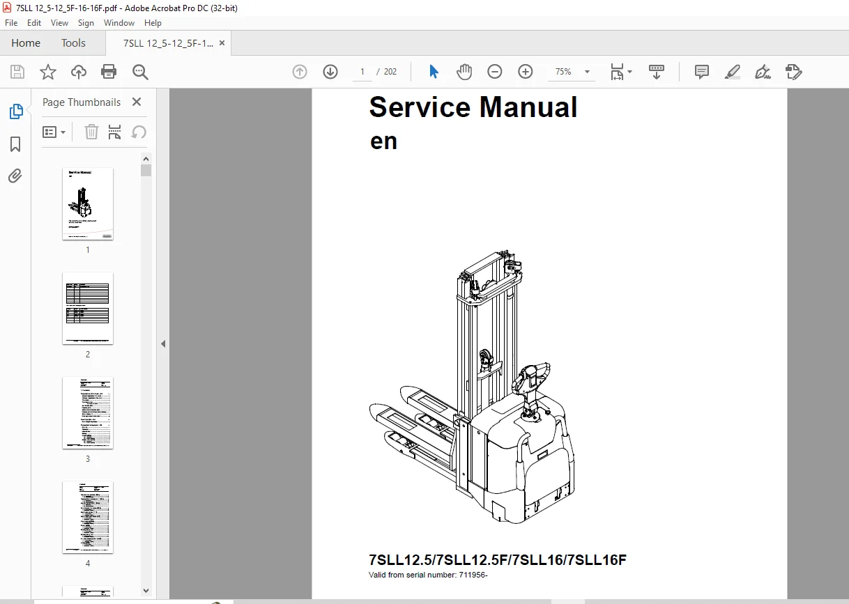
Toyota Forklift 7SLL12.5 7SLL12.5F 7SLL16 7SLL16F Service Manual SN 711956 – PDF DOWNLOAD
$28.95
Toyota Forklift 7SLL12.5 7SLL12.5F 7SLL16 7SLL16F Service Manual SN 711956 – PDF DOWNLOAD
Instant PDF Download
Available immediately
Save to Your Device
Download & keep forever
Antivirus Scanned
100% virus-free
Trusted Worldwide
175,000+ customers
Description
Toyota Forklift 7SLL12.5 7SLL12.5F 7SLL16 7SLL16F Service Manual SN 711956 – PDF DOWNLOAD
FILE DETAILS:
Toyota Forklift 7SLL12.5 7SLL12.5F 7SLL16 7SLL16F Service Manual SN 711956 – PDF DOWNLOAD
Language : English
Pages : 156
Downloadable : Yes
File Type : PDF
DESCRIPTION:
Toyota Forklift 7SLL12.5 7SLL12.5F 7SLL16 7SLL16F Service Manual SN 711956 – PDF DOWNLOAD
Presentation of the truck – M2:
- The truck is a battery driven support arm truck. The truck is equipped with a tiller arm for optional control: standing on the ride-on platform or walking. Best advantage can be taken of the truck’s properties by the operator standing on the ergonomically designed platform as this provides the operator with a clear view over the truck and load, allowing work to be carried out with ease and safety.
- The truck is also equipped with protective gates to protect the operator when driving standing on the platform. When the gates are retracted the truck’s maximum speed is always 6 km/h. When the gates are raised and the operator is standing on the platform the truck’s maximum speed is 8 km/h.
- The tiller arm is specially designed to provide the best possible operator ergonomy, having all the controls and buttons within easy reach without the operator needing to release the handle. The tiller arm is also equipped with a display showing running time and battery status among other things. The display is also used when the operator wishes to change any of the operator parameters with which the truck can be programmed.
- The truck is equipped with the patented PowerTrak system, which means that the drive wheel pressure is adjusted according to the weight of the load and the wear on the drive wheel. This reduces the wear and tear on the drive wheel and ensures safer load handling.
- The truck has a 24V electrical system and the speed is regulated by means of a transistor controller to provide gentle control of acceleration and speed while driving.
- The forks are lifted using a compact, yet powerful hydraulic unit. Lifting is controlled by a transistorised variable speed controller. The truck’s proportional valve is used to adjust the lowering speed and fork positioning during stacking.
- The battery compartment is designed to allow the battery to be changed from either side as well as from above, which means the truck is well suited to most types of battery changing situations.
TABLE OF CONTENTS:
Toyota Forklift 7SLL12.5 7SLL12.5F 7SLL16 7SLL16F Service Manual SN 711956 – PDF DOWNLOAD
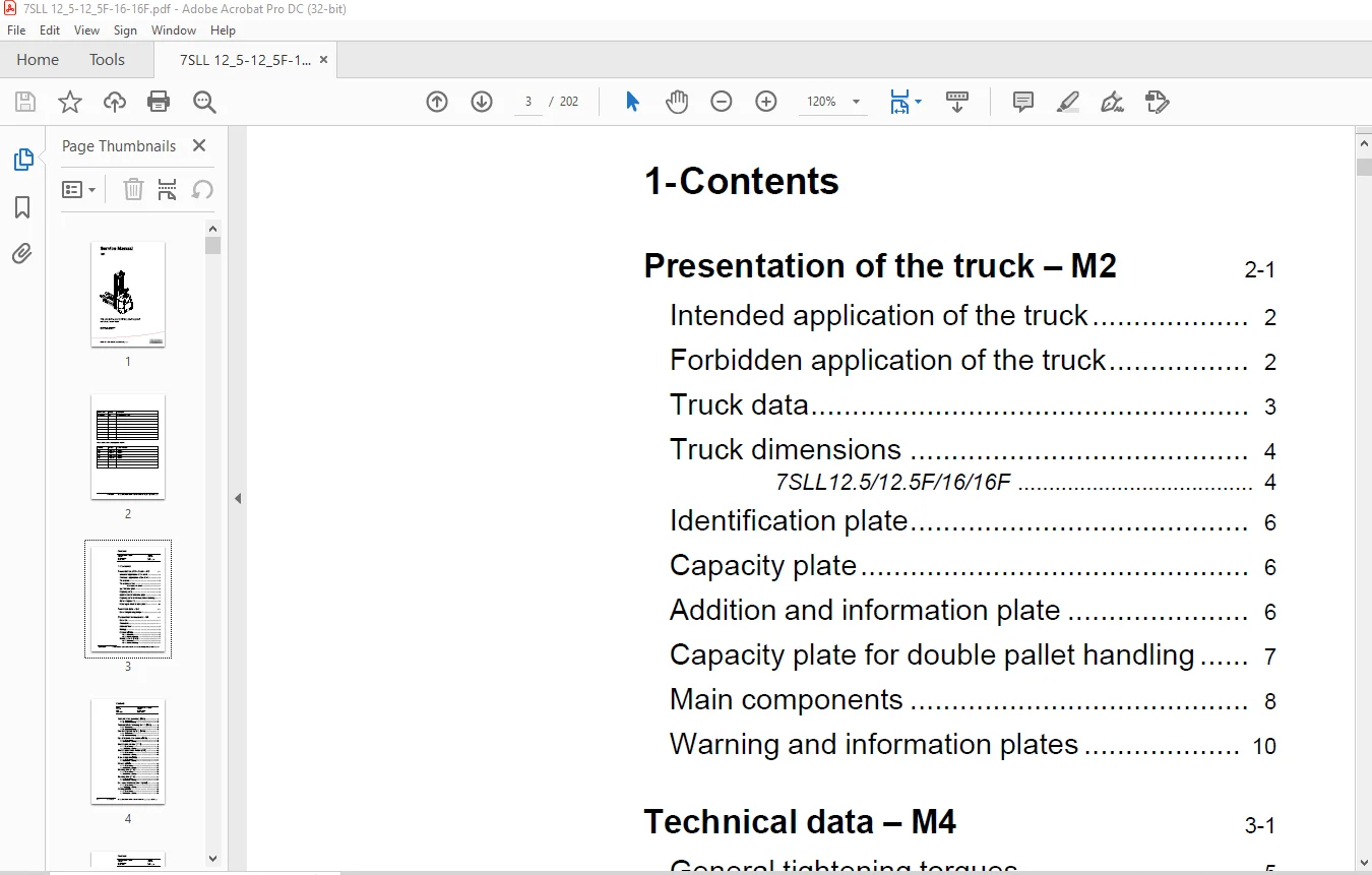
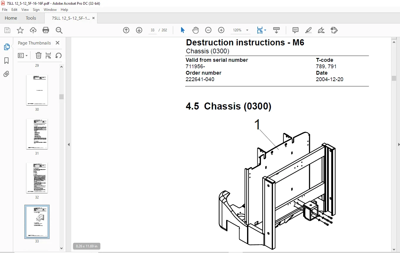
1- Contents.............................................................................  3
2- Presentation of the truck - M2....................................................... 13
	2.1 Intended application of the truck............................................... 14
	2.2 Forbidden application of the truck.............................................. 14
	2.3 Truck data...................................................................... 15
	2.4 Truck dimensions................................................................ 16
		7SLL12.5/12.5F/16/16F........................................................... 16
	2.5 Identification plate............................................................ 18
	2.6 Capacity plate.................................................................. 18
	2.7 Addition and information plate.................................................. 18
	2.8 Capacity plate for double pallet handling....................................... 19
	2.9 Main components................................................................. 20
	2.10 Warning and information plates................................................. 22
3- Technical data - M4.................................................................. 25
	3.1 General tightening torques...................................................... 29
4- Destruction instructions - M6........................................................ 31
	4.1 General......................................................................... 31
	4.2 Procedure....................................................................... 31
	4.3 Abbreviations................................................................... 32
	4.4 Sorting......................................................................... 32
	4.5 Chassis (0300).................................................................. 33
		4.5.1 Dismantling............................................................... 33
		4.5.2 Material handling......................................................... 33
	4.6 Hoods, covers (0340)............................................................ 34
		4.6.1 Dismantling............................................................... 34
		4.6.2 Material handling......................................................... 34
	4.7 Fork structure (low-lifter) (0380).............................................. 35
		4.7.1 Dismantling............................................................... 35
		4.7.2 Material handling......................................................... 35
	4.8 Travel platform including mount (0560).......................................... 36
		4.8.1 Dismantling............................................................... 36
		4.8.2 Material handling......................................................... 36
	4.9 Overhead guard (option) (0810).................................................. 37
		4.9.1 Dismantling............................................................... 37
		4.9.2 Material handling......................................................... 37
	4.10 Operator protective device (0840).............................................. 38
		4.10.1 Dismantling.............................................................. 38
		4.10.2 Material handling........................................................ 38
	4.11 Electric pump motor (1710)..................................................... 39
		4.11.1 Dismantling.............................................................. 39
		4.11.2 Material handling........................................................ 39
	4.12 Electric travel drive motor (1760)............................................. 40
		4.12.1 Dismantling.............................................................. 40
		4.12.2 Material handling........................................................ 40
	4.13 Drive unit/gear (2550)......................................................... 41
		4.13.1 Dismantling.............................................................. 41
		4.13.2 Material handling........................................................ 41
	4.14 Wheels (3500).................................................................. 42
		4.14.1 Dismantling.............................................................. 42
		4.14.2 Material handling........................................................ 42
	4.15 Steering arm (4110)............................................................ 43
		4.15.1 Dismantling.............................................................. 43
		4.15.2 Material handling........................................................ 43
	4.16 Steering arm (4110)............................................................ 44
		4.16.1 Dismantling.............................................................. 44
		4.16.2 Material handling........................................................ 44
	4.17 General electric equipment (5100).............................................. 45
		4.17.1 Dismantling.............................................................. 45
		4.17.2 Material handling........................................................ 45
	4.18 Cabling (5590)................................................................. 46
		4.18.1 Dismantling.............................................................. 46
		4.18.2 Material handling........................................................ 46
	4.19 Steering and protective electronics (5700)..................................... 47
		4.19.1 Dismantling.............................................................. 47
		4.19.2 Material handling........................................................ 47
	4.20 Lift/lowering sensor (5820) and safety sensor (5830)........................... 48
		4.20.1 Dismantling.............................................................. 48
		4.20.2 Material handling........................................................ 48
	4.21 Hydraulic unit (6100).......................................................... 49
		4.21.1 Dismantling.............................................................. 49
		4.21.2 Material handling........................................................ 49
	4.22 Main mast (7100)............................................................... 50
		4.22.1 Dismantling.............................................................. 50
		4.22.2 Material handling........................................................ 50
	4.23 Chassis-mounted hydraulic oil lines (6230) (and main lift cylinder (6610) ).... 51
		4.23.1 Dismantling.............................................................. 51
		4.23.2 Material handling........................................................ 51
	4.24 Battery charger connector (9380)............................................... 52
		4.24.1 Dismantling.............................................................. 52
		4.24.2 Material handling........................................................ 52
5- Installation and maintenance instructions - P1....................................... 53
	5.1 Truck installation.............................................................. 53
		5.1.1 Lifting the truck......................................................... 53
		5.1.2 Battery installation...................................................... 54
		5.1.3 Putting into service...................................................... 54
	5.2 Introduction, maintenance....................................................... 56
		5.2.1 Safety rules during maintenance work...................................... 56
	5.3 Cleaning and washing............................................................ 58
		5.3.1 External cleaning......................................................... 58
		5.3.2 Cleaning the motor compartment............................................ 58
		5.3.3 Electric components....................................................... 58
	5.4 Safe lifting.................................................................... 59
6- Maintenance schedule - P2............................................................ 61
	6.1 Lubrication chart............................................................... 67
7- Oil and grease specification - P3.................................................... 69
8- Tools - P4........................................................................... 71
	8.1 Super Seal connectors........................................................... 71
	8.2 AMP connectors.................................................................. 72
		8.2.1 AMP Connectors, 040 series................................................ 73
	8.3 Molex connectors................................................................ 73
	8.4 Other tools..................................................................... 74
9- Electric drive motor - 1760.......................................................... 75
	9.1 Included components............................................................. 75
	9.2 Disassembly/assembly of the truck motor......................................... 77
		9.2.1 Disassembly............................................................... 77
		9.2.2 Assembly.................................................................. 77
	9.3 Service/repairs................................................................. 78
		9.3.1 Disassembly of the motor.................................................. 78
		9.3.2 Motor installation........................................................ 79
		9.3.3 Cleaning.................................................................. 79
	9.4 Technical data.................................................................. 80
10- Drive unit/gear - 2550.............................................................. 81
	10.1 Included components............................................................ 82
		10.1.1 Technical data........................................................... 83
	10.2 Leakage from top cover......................................................... 83
	10.3 Replacing the drive axle jointing ring......................................... 83
		10.3.1 Disassembly.............................................................. 84
		10.3.2 Assembly................................................................. 84
11- Electromagnetic brake - 3370........................................................ 85
	11.1 Main components of the brake................................................... 85
	11.2 Maintenance.................................................................... 86
		11.2.1 Basic adjustment of the play............................................. 86
		11.2.2 Brake disc replacement................................................... 87
12- Electrical systems - 5000........................................................... 89
	12.1 Electrical equipment overview.................................................. 89
	12.2 Equipment list and electrical diagram.......................................... 91
		12.2.1 Electrical wiring diagram 1 of 15........................................ 95
		12.2.2 Electrical wiring diagram 2 of 15........................................ 96
		12.2.3 Electrical wiring diagram 3 of 15........................................ 97
		12.2.4 Electrical wiring diagram 4 of 15........................................ 98
		12.2.5 Electrical wiring diagram 5 of 15........................................ 99
		12.2.6 Electrical wiring diagram 6 of 15........................................100
		12.2.7 Electrical wiring diagram 7 of 15........................................101
		12.2.8 Electrical wiring diagram 8 of 15........................................102
		12.2.9 Electrical wiring diagram 9 of 15........................................103
		12.2.10 Electrical wiring diagram 10 of 15......................................104
		12.2.11 Electrical wiring diagram 11 of 15......................................105
		12.2.12 Electrical wiring diagram 12 of 15......................................106
		12.2.13 Electrical wiring diagram 13 of 15......................................107
		12.2.14 Electrical wiring diagram 14 of 15......................................108
		12.2.15 Electrical wiring diagram 15 of 15......................................109
	12.3 Functional description.........................................................110
		12.3.1 Description of steering system...........................................116
	12.4 Speed limitation...............................................................117
	12.5 Hour meter and battery condition...............................................118
	12.6 Diagnostic and troubleshooting.................................................120
		12.6.1 Fault codes..............................................................120
		12.6.2 Fault code history.......................................................120
		12.6.3 List of fault codes......................................................121
		12.6.4 Transistor regulator troubleshooting and error codes.....................129
			General.....................................................................129
			Transistor regulator errors.................................................129
			Resetting errors............................................................131
			Safety......................................................................131
		12.6.5 Built-in Test Function...................................................132
			Digital inputs/outputs test mode............................................134
		12.6.6 Display test mode........................................................137
	12.7 Part numbers...................................................................138
	12.8 Parameters.....................................................................139
		12.8.1 General..................................................................139
		12.8.2 Viewing parameters -CAN key not connected................................139
		12.8.3 Viewing parameters -CAN key connected....................................140
		12.8.4 Setting Driver parameters................................................141
		12.8.5 Setting Service parameters...............................................141
		12.8.6 Summary of driver parameters.............................................142
		12.8.7 Description of driver parameters.........................................143
			# 2 - Maximum speed, high range.............................................143
			# 3 - Maximum acceleration..................................................143
			# 4 - Neutral braking effect................................................143
			# 6 - Maximum speed, low range..............................................143
			# 7 - Maximum speed, “Turtle” mode..........................................143
		12.8.8 Summary of service parameters............................................144
		12.8.9 Description of service parameters........................................146
			# 10 - PIN code.............................................................146
			To enter a new PIN-code:....................................................146
			To remove an existing PIN-code:.............................................147
			# 14 - Creep speed..........................................................147
			#15 - Non-configurable options..............................................147
			#16 - Configurable option #1................................................147
			#17 - Configurable option #2................................................147
			#18 - Configurable option #3................................................147
			#19 - Configurable option #4................................................147
			# 20 - Hour meter selection.................................................148
			# 21 - Battery size.........................................................148
			# 22 - Maximum fork lowering speed..........................................149
			# 23 - Fork lower stop ramp.................................................149
			# 25 - Service interval.....................................................149
			# 35 - Log off..............................................................149
			# 36 - Calibrate............................................................150
			# 37 - Steering offset......................................................153
			# 38 - Steer servo activated................................................153
			# # 39 - Log-in method & operator parameter access..........................153
			Extended keypad - General...................................................154
			Extended keypad - Programming...............................................154
		12.8.10 “Option” Parameters.....................................................156
			General.....................................................................156
			Parameter #15 Non-configurable options......................................156
			Setting Non-configurable options............................................157
			Parameter #16 to #19 Configurable options...................................158
	12.9 Technical specifications - Curtis 1243.........................................164
13- Hydraulic system - 6000.............................................................165
	13.1 Hydraulic diagram..............................................................165
		13.1.1 7SLL12.5F/16FL...........................................................165
		13.1.2 7SLL12.5/16..............................................................166
		13.1.3 Main components..........................................................167
		13.1.4 Description..............................................................168
			The PowerTrak system........................................................168
			Working pressure............................................................169
			Overflow valve..............................................................169
			Pressure sensor.............................................................169
14- Main lift chain system - 7120.......................................................171
	14.1 General........................................................................171
	14.2 Checking the chain setting.....................................................171
	14.3 Chain inspection...............................................................171
		14.3.1 Noise....................................................................171
		14.3.2 Surface rust.............................................................171
		14.3.3 Rusty links..............................................................171
		14.3.4 Stiff links..............................................................172
		14.3.5 Bolt rotation............................................................172
		14.3.6 Loose bolts..............................................................172
		14.3.7 Outline wear.............................................................173
		14.3.8 Stretching...............................................................174
		14.3.9 Damage...................................................................175
		14.3.10 Damaged discs...........................................................175
		14.3.11 Damaged bolts...........................................................175
		14.3.12 Dirty chain.............................................................176
	14.4 Cleaning.......................................................................176
	14.5 Lubrication....................................................................176
15- Control/computer equipment - 8700...................................................179
	15.1 General........................................................................179
	15.2 Connection.....................................................................179
	15.3 Layout.........................................................................180
		15.3.1 Main program screen......................................................180
		15.3.2 Nodes....................................................................180
		15.3.3 Icons....................................................................181
		15.3.4 Tool buttons and menu bar................................................182
		15.3.5 Information window.......................................................182
		15.3.6 Status bar...............................................................182
	15.4 Connection function............................................................182
	15.5 Disconnection function.........................................................183
	15.6 Downloading program function...................................................183
		15.6.1 Normal downloading (truck with key)......................................183
		15.6.2 Normal downloading (truck with keypad)...................................184
		15.6.3 Emergency downloading (truck with keypad)................................184
		15.6.4 Downloading in old versions of logic card................................185
		15.6.5 Emergency downloading (truck with keypad)................................185
	15.7 Truck report function..........................................................186
	15.8 Parameters function............................................................187
	15.9 Diagnostics function...........................................................189
		15.9.1 Representation of signal colours.........................................189
		15.9.2 “Tiller arm” tab.........................................................190
		15.9.3 “Drive Controller” tab...................................................191
	15.10 Other menu functions..........................................................192
		15.10.1 Save to file............................................................192
		15.10.2 Download from file......................................................192
		15.10.3 Reset CAN adapter.......................................................192
		15.10.4 Delete error code log...................................................192
		15.10.5 Reset hour meter........................................................192
		15.10.6 Read error code log.....................................................192
		15.10.7 Adjust date and time....................................................192
		15.10.8 Adjusting the hour meter on older cards.................................193
		15.10.9 Help....................................................................193
			About TruckCom..............................................................193
		15.10.10 Exit...................................................................193
	15.11 Specifications................................................................193
	15.12 Installation..................................................................194
		15.12.1 Installation on a PC with Windows® 95/98................................194
		15.12.2 Installation on a PC with Windows XP/2000...............................194
		15.12.3 Installation on a PC with Windows NT....................................200
		15.12.4 In case of communication problems with CAN..............................200
		15.12.5 To uninstall............................................................200
IMAGES PREVIEW OF THE MANUAL:
Questions? Email us: [email protected]
PLEASE NOTE:
- This is the same manual used by the DEALERSHIPS to SERVICE your vehicle.
- The manual can be all yours – Once payment is complete, you will be taken to the download page from where you can download the manual. All in 2-5 minutes time!!
- Need any other service / repair / parts manual, please feel free to contact us at heydownloadss @gmail.com . We may surprise you with a nice offer
S.V