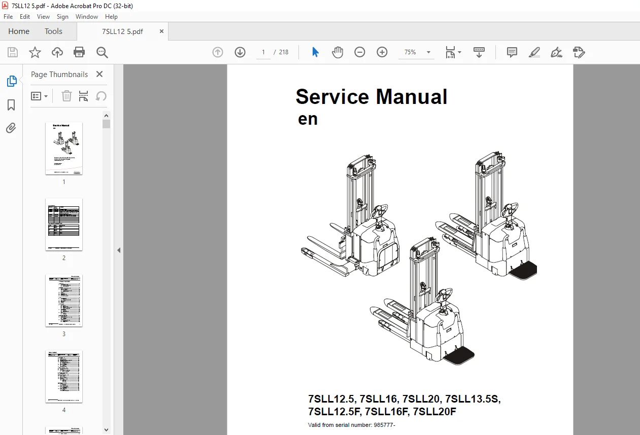
Toyota Forklift 7SLL12.5 7SLL16 7SLL20 7SLL13.5S 7SLL12.5F 7SLL16F 7SLL20F Service Manual SN 985777 – PDF DOWNLOAD
$28.95
Toyota Forklift 7SLL12.5 7SLL16 7SLL20 7SLL13.5S 7SLL12.5F 7SLL16F 7SLL20F Service Manual SN 985777 – PDF DOWNLOAD
Description
Toyota Forklift 7SLL12.5 7SLL16 7SLL20 7SLL13.5S 7SLL12.5F 7SLL16F 7SLL20F Service Manual SN 985777 – PDF DOWNLOAD
FILE DETAILS:
Toyota Forklift 7SLL12.5 7SLL16 7SLL20 7SLL13.5S 7SLL12.5F 7SLL16F 7SLL20F Service Manual SN 985777 – PDF DOWNLOAD
Language : English
Pages : 218
Downloadable : Yes
File Type : PDF
DESCRIPTION:
Toyota Forklift 7SLL12.5 7SLL16 7SLL20 7SLL13.5S 7SLL12.5F 7SLL16F 7SLL20F Service Manual SN 985777 – PDF DOWNLOAD
Maintenance:
- To assure maximum safety and minimum downtime, all items in the service programme should be covered. The service intervals are only guidelines and need not be strictly followed.
- The operator of the truck should adapt these to local requirements, however, it is important that the minimum requirements as stated by TOYOTA are observed.
The service intervals are based on truck operating hours and can be adapted to most common 8-hour shifts. When calculating the service intervals, the following operating hours have been used:
Day time: 08.00-17.00 (20 hours/week)
Double shift: 06.00-14.00, 14.00-22.00 (40 hours/week)
Triple shift: 06.00-14.00, 14.00-22.00, 22.00-06.00 (60 hours/week)
- Make sure the truck receives the necessary regular maintenance service according to the maintenance schedule. The truck’s safety, efficiency and service life rely on the service and maintenance the truck receives.
- For service and repairs, only use spare parts approved by TOYOTA.
3.1 Safety rules during maintenance work:
Only technicians who have received the necessary training for service and repairs of this truck type may carry out service and repair work.
• Do not perform any repair work on the truck unless properly trained
and possessing the necessary skills to perform such work.
• Keep the service site clean. Oil and water on the floor could make it
slippery.
• Never wear loose items and jewellery when working on the truck.
IMAGES PREVIEW OF THE MANUAL:
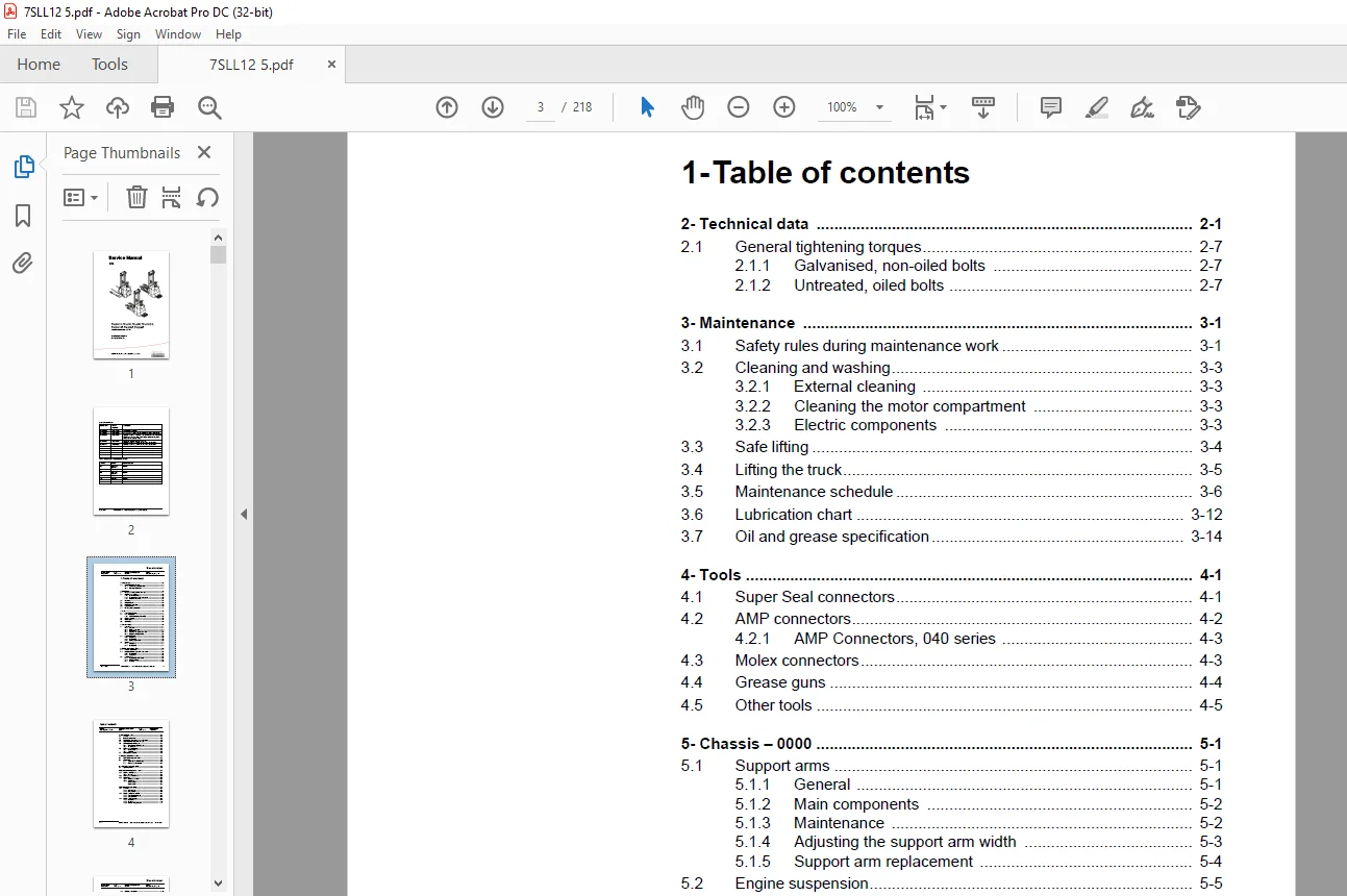
TABLE OF CONTENTS:
Toyota Forklift 7SLL12.5 7SLL16 7SLL20 7SLL13.5S 7SLL12.5F 7SLL16F 7SLL20F Service Manual SN 985777 – PDF DOWNLOAD
1- Table of contents....................................................................  3
2- Technical data....................................................................... 11
	2.1 General tightening torques...................................................... 17
		2.1.1 Galvanised, non-oiled bolts............................................... 17
		2.1.2 Untreated, oiled bolts.................................................... 17
3- Maintenance.......................................................................... 19
	3.1 Safety rules during maintenance work............................................ 19
	3.2 Cleaning and washing............................................................ 21
		3.2.1 External cleaning......................................................... 21
		3.2.2 Cleaning the motor compartment............................................ 21
		3.2.3 Electric components....................................................... 21
	3.3 Safe lifting.................................................................... 22
	3.4 Lifting the truck............................................................... 23
	3.5 Maintenance schedule............................................................ 24
	3.6 Lubrication chart............................................................... 30
	3.7 Oil and grease specification.................................................... 32
4- Tools................................................................................ 33
	4.1 Super Seal connectors........................................................... 33
	4.2 AMP connectors.................................................................. 34
		4.2.1 AMP Connectors, 040 series................................................ 35
	4.3 Molex connectors................................................................ 35
	4.4 Grease guns..................................................................... 36
	4.5 Other tools..................................................................... 37
5- Chassis - 0000....................................................................... 39
	5.1 Support arms.................................................................... 39
		5.1.1 General................................................................... 39
		5.1.2 Main components........................................................... 40
		5.1.3 Maintenance............................................................... 40
		5.1.4 Adjusting the support arm width........................................... 41
		5.1.5 Support arm replacement................................................... 42
	5.2 Engine suspension............................................................... 43
		5.2.1 Components................................................................ 43
		5.2.2 Disassembly............................................................... 43
		5.2.3 Spring replacement........................................................ 44
	5.3 Platform........................................................................ 45
		5.3.1 Components................................................................ 45
		5.3.2 Disassembly............................................................... 45
6- Electric drive motor - 1760.......................................................... 47
	6.1 Included components............................................................. 47
	6.2 Disassembly/assembly of the truck motor......................................... 49
		6.2.1 Disassembly............................................................... 49
		6.2.2 Assembly.................................................................. 49
	6.3 Service/repairs................................................................. 50
		6.3.1 Disassembly of the motor.................................................. 50
		6.3.2 Motor installation........................................................ 50
		6.3.3 Cleaning.................................................................. 51
7- Drive unit/gear - 2550............................................................... 53
	7.1 General......................................................................... 53
	7.2 Included components............................................................. 54
	7.3 Disassembly of the drive unit from the truck.................................... 56
	7.4 Assembly of the drive unit in the truck......................................... 56
	7.5 Oil inspection or changing oil.................................................. 57
		7.5.1 Oil inspection/replenishment.............................................. 57
		7.5.2 Changing oil.............................................................. 57
	7.6 Replacing the gasket ring....................................................... 57
		7.6.1 Disassembly............................................................... 57
		7.6.2 Assembly.................................................................. 58
	7.7 Leakage from top cover.......................................................... 58
8- Electromagnetic brake - 3370......................................................... 59
	8.1 Main components of the brake.................................................... 59
	8.2 Maintenance..................................................................... 60
		8.2.1 Basic adjustment of the play.............................................. 60
		8.2.2 Brake disc replacement.................................................... 61
9- Support/Castor Wheels - 3540......................................................... 63
	9.1 Tightening torque............................................................... 63
10- Electrical steering system - 4300................................................... 65
	10.1 Electrical steering servo...................................................... 65
		10.1.1 General.................................................................. 65
	10.2 Steering servo components...................................................... 66
	10.3 Adjustment..................................................................... 67
		10.3.1 Reference sensor......................................................... 67
		10.3.2 Calibration.............................................................. 67
			Parameter 36................................................................ 67
			Parameter 37................................................................ 67
11- Electrical systems - 5000........................................................... 69
	11.1 General........................................................................ 69
		11.1.1 Part numbers............................................................. 69
		11.1.2 Nomenclature............................................................. 70
	11.2 Electrical equipment overview.................................................. 71
		11.2.1 Component placement...................................................... 71
		11.2.2 Component list........................................................... 73
	11.3 Electrical wiring diagram...................................................... 77
		11.3.1 Symbol list.............................................................. 77
		11.3.2 Overview................................................................. 78
		11.3.3 Detailed wiring diagram.................................................. 79
	11.4 Functional description......................................................... 95
		11.4.1 Principle of operation................................................... 95
		11.4.2 Description of steering system...........................................100
		11.4.3 Spider expansion unit (SEU)..............................................100
		11.4.4 Speed limitation.........................................................102
		11.4.5 Hour meter and battery condition.........................................103
		11.4.6 TLS - Truck log system (optional)........................................104
			General.....................................................................104
			Registration................................................................104
			Logging in/out SD16.........................................................104
			Logging in/out S16..........................................................104
			Collision sensor............................................................105
			Settings....................................................................105
		11.4.7 ID unit (optional).......................................................105
	11.5 Parameters.....................................................................106
		11.5.1 General..................................................................106
		11.5.2 Viewing parameters -CAN key not connected................................106
		11.5.3 Viewing parameters - CAN key connected...................................107
		11.5.4 Setting Driver parameters................................................108
		11.5.5 Setting Service parameters...............................................108
		11.5.6 Summary of driver parameters.............................................109
		11.5.7 Description of driver parameters.........................................110
			# 2 - Maximum speed, high range.............................................110
			# 3 - Maximum acceleration..................................................110
			# 4 - Neutral braking effect................................................110
			# 6 - Maximum speed, low range..............................................110
			# 7 - Maximum speed, “Turtle” mode..........................................110
		11.5.8 Summary of service parameters............................................111
		11.5.9 Description of service parameters........................................113
			# 10 - PIN code.............................................................113
			To enter a new PIN-code:....................................................113
			To remove an existing PIN-code:.............................................114
			# 14 - Creep speed..........................................................114
			#15 - Non-configurable options..............................................114
			Setting Non-configurable options............................................114
			#16 - Configurable option #1................................................115
			#17 - Configurable option #2................................................115
			#18 - Configurable option #3................................................115
			#19 - Configurable option #4................................................116
			# 20 - Hour meter selection.................................................116
			# 21 - Battery size.........................................................117
			# 22 - Maximum fork lowering speed..........................................117
			# 23 - Fork lower stop ramp.................................................117
			# 25 - Service interval.....................................................117
			# 26 - Selection of hydraulic unit..........................................117
			# 35 - Log off..............................................................118
			# 36 - Calibrate............................................................118
			# 37 - Steering offset......................................................121
			# 38 - Steer servo activated................................................121
			# # 39 - Log-in method & operator parameter access..........................122
			Extended keypad - General...................................................122
			Extended keypad - Programming...............................................123
		11.5.10 Configurable “Option” Parameters........................................125
			General.....................................................................125
			Parameter #16 to #19 Configurable options...................................126
	11.6 Diagnostic and troubleshooting.................................................139
		11.6.1 General..................................................................139
		11.6.2 Fault code history.......................................................140
		11.6.3 List of fault codes......................................................141
		11.6.4 Transistor regulator.....................................................148
			General.....................................................................148
			Transistor regulator errors.................................................149
			Resetting errors............................................................150
			Safety......................................................................150
		11.6.5 Built-in Test Function...................................................151
			Digital inputs/outputs test mode............................................153
		11.6.6 Display test mode........................................................156
	11.7 Technical specifications - Curtis 1243.........................................157
12- Hydraulic system - 6000.............................................................159
	12.1 Hydraulic diagram..............................................................159
		12.1.1 With support arm lift....................................................159
		12.1.2 Without support arm lift.................................................160
	12.2 Main Components................................................................161
		With support arm lift...........................................................161
		Without support arm lift........................................................161
	12.3 Description....................................................................162
		12.3.1 Lifting system...........................................................162
		12.3.2 The PowerTrak system.....................................................162
		12.3.3 Working pressure.........................................................163
		12.3.4 Overflow valve...........................................................163
		12.3.5 Pressure sensor..........................................................163
13- Lift mast - 7000....................................................................165
	13.1 Mast incline...................................................................165
	13.2 Main lift chain system.........................................................166
		13.2.1 Checking the chain setting...............................................166
		13.2.2 Chain inspection.........................................................166
			Noise.......................................................................166
			Surface rust................................................................166
			Rusty links.................................................................166
			Stiff links.................................................................166
			Bolt rotation...............................................................167
			Loose bolts.................................................................167
			Outline wear................................................................167
			Stretching..................................................................168
			Damage......................................................................169
			Damaged discs...............................................................169
			Damaged bolts...............................................................169
			Dirty chain.................................................................169
		13.2.3 Cleaning.................................................................169
		13.2.4 Lubrication..............................................................170
14- TruckCom............................................................................173
	14.1 General........................................................................173
	14.2 Connection.....................................................................173
	14.3 Layout.........................................................................174
		14.3.1 Main program screen......................................................174
		14.3.2 Nodes....................................................................174
		14.3.3 Icons....................................................................175
		14.3.4 Tool buttons and menu bar................................................175
		14.3.5 Information window.......................................................176
		14.3.6 Status bar...............................................................176
	14.4 Connection function............................................................176
	14.5 Disconnection function.........................................................176
	14.6 Downloading program function...................................................177
		14.6.1 Normal downloading (truck with key)......................................177
		14.6.2 Normal downloading (truck with keypad)...................................177
		14.6.3 Emergency downloading (truck with keypad)................................178
		14.6.4 Emergency downloading (truck with keypad)................................178
		14.6.5 Downloading in old versions of logic card................................178
	14.7 Truck report function..........................................................179
	14.8 Parameters function............................................................180
	14.9 Diagnostics function...........................................................180
		14.9.1 Representation of signal colours.........................................181
		14.9.2 “Tiller arm” tab.........................................................181
		14.9.3 “Drive Controller” tab (transistor regulator driving)....................182
		14.9.4 “Pump controller” tab (transistor regulator pump)........................183
		14.9.5 “EPS” (steering servo tab)...............................................184
		14.9.6 SEU tab (Extra I/O module)...............................................185
	14.10 Other menu functions..........................................................185
		14.10.1 Save to file............................................................185
		14.10.2 Download from file......................................................185
		14.10.3 Reset CAN adapter.......................................................186
		14.10.4 Delete error code log...................................................186
		14.10.5 Reset hour meter........................................................186
		14.10.6 Read error code log.....................................................186
		14.10.7 Adjust date and time....................................................186
		14.10.8 Adjusting the hour meter on older cards.................................186
		14.10.9 Help....................................................................186
			About the TruckCom application..............................................186
		14.10.10 Exit...................................................................186
	14.11 Specifications................................................................187
	14.12 Installation..................................................................187
		14.12.1 Installation on a PC with Windows® 95/98................................187
		14.12.2 Installation on a PC with Windows XP/ 2000..............................188
			Changes in Windows® Control Panel...........................................190
		14.12.3 Installation on a PC with Windows NT....................................193
		14.12.4 In case of communication problems with CAN..............................193
		14.12.5 To uninstall............................................................193
15- Destruction instructions............................................................195
	15.1 General........................................................................195
	15.2 Procedure......................................................................195
	15.3 Abbreviations..................................................................196
	15.4 Sorting........................................................................196
	15.5 Chassis (0300).................................................................197
		15.5.1 Dismantling..............................................................197
		15.5.2 Material handling........................................................197
	15.6 Hoods, covers (0340)...........................................................198
		15.6.1 Dismantling..............................................................198
		15.6.2 Material handling........................................................198
	15.7 Fork structure (low-lifter) (0380).............................................199
		15.7.1 Dismantling..............................................................199
		15.7.2 Material handling........................................................199
	15.8 Travel platform including mount (0560).........................................200
		15.8.1 Dismantling..............................................................200
		15.8.2 Material handling........................................................200
	15.9 Overhead guard (option) (0810).................................................201
		15.9.1 Dismantling..............................................................201
		15.9.2 Material handling........................................................201
	15.10 Operator protective device (0840).............................................202
		15.10.1 Dismantling.............................................................202
		15.10.2 Material handling.......................................................202
	15.11 Electric pump motor (1710)....................................................203
		15.11.1 Dismantling.............................................................203
		15.11.2 Material handling.......................................................203
	15.12 Electric travel drive motor (1760)............................................204
		15.12.1 Dismantling.............................................................204
		15.12.2 Material handling.......................................................204
	15.13 Drive unit/gear (2550)........................................................205
		15.13.1 Dismantling.............................................................205
		15.13.2 Material handling.......................................................205
	15.14 Wheels (3500).................................................................206
		15.14.1 Dismantling.............................................................206
		15.14.2 Material handling.......................................................206
	15.15 Steering arm (4110)...........................................................207
		15.15.1 Dismantling.............................................................207
		15.15.2 Material handling.......................................................207
	15.16 Steering arm (4110)...........................................................208
		15.16.1 Dismantling.............................................................208
		15.16.2 Material handling.......................................................208
	15.17 General electric equipment (5100).............................................209
		15.17.1 Dismantling.............................................................209
		15.17.2 Material handling.......................................................209
	15.18 Cabling (5590)................................................................210
		15.18.1 Dismantling.............................................................210
		15.18.2 Material handling.......................................................210
	15.19 Steering and protective electronics (5700)....................................211
		15.19.1 Dismantling.............................................................211
		15.19.2 Material handling.......................................................211
	15.20 Lift/lowering sensor (5820) and safety sensor (5830)..........................212
		15.20.1 Dismantling.............................................................212
		15.20.2 Material handling.......................................................212
	15.21 Hydraulic unit (6100).........................................................213
		15.21.1 Dismantling.............................................................213
		15.21.2 Material handling.......................................................213
	15.22 Main mast (7100)..............................................................214
		15.22.1 Dismantling.............................................................214
		15.22.2 Material handling.......................................................214
	15.23 Chassis-mounted hydraulic oil lines (6230) (and main lift cylinder (6610))....215
		15.23.1 Dismantling.............................................................215
		15.23.2 Material handling.......................................................215
	15.24 Battery charger connector (9380)..............................................216
		15.24.1 Dismantling.............................................................216
		15.24.2 Material handling.......................................................216
Contact us: [email protected]
PLEASE NOTE:
- This is not a physical manual but a digital manual – meaning no physical copy will be couriered to you. The manual can be yours in the next 2 mins as once you make the payment, you will be directed to the download page IMMEDIATELY.
- This is the same manual used by the dealers inorder to diagnose your vehicle of its faults.
- Require some other service manual or have any queries: please WRITE to us at [email protected]
S.V