Trusted Business
Verified & Licensed
Virus Free Files
100% Safe Downloads
Secure Payment
SSL Protected
Instant Delivery
Available Immediately
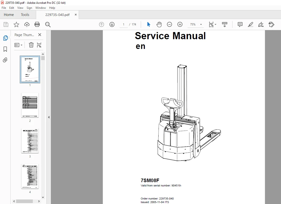
Toyota Forklift 7SM08F Service Manual SN 904519 – PDF DOWNLOAD
$27.95
Toyota Forklift 7SM08F Service Manual SN 904519 – PDF DOWNLOAD
Instant PDF Download
Available immediately
Save to Your Device
Download & keep forever
Antivirus Scanned
100% virus-free
Trusted Worldwide
175,000+ customers
Description
Toyota Forklift 7SM08F Service Manual SN 904519 – PDF DOWNLOAD
FILE DETAILS:
Toyota Forklift 7SM08F Service Manual SN 904519 – PDF DOWNLOAD
Language : English
Pages : 174
Downloadable : Yes
File Type : PDF
IMAGES PREVIEW OF THE MANUAL:
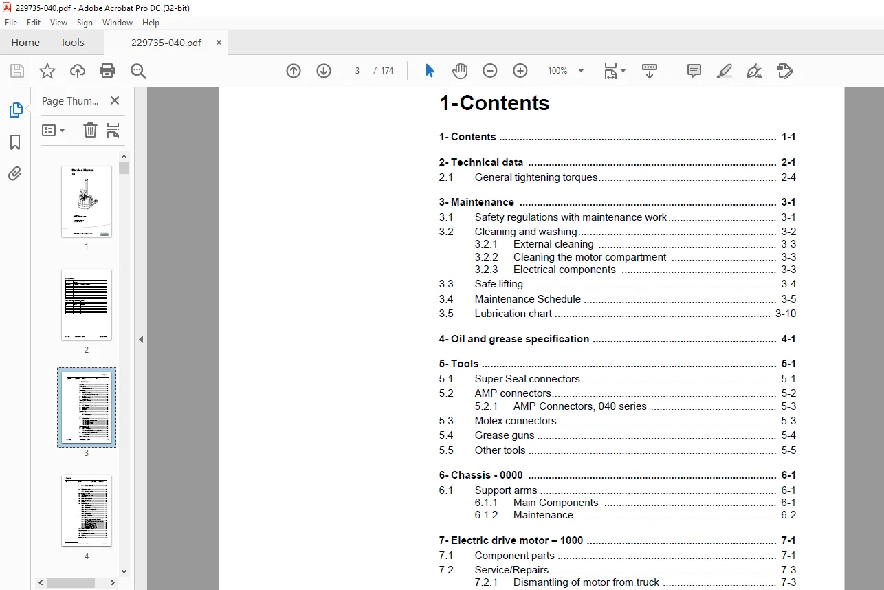
TABLE OF CONTENTS:
Toyota Forklift 7SM08F Service Manual SN 904519 – PDF DOWNLOAD
1- Contents....................................................................  3
2- Technical data..............................................................  7
	2.1 General tightening torques............................................. 10
3- Maintenance................................................................. 11
	3.1 Safety regulations with maintenance work............................... 11
	3.2 Cleaning and washing................................................... 12
		3.2.1 External cleaning................................................ 13
		3.2.2 Cleaning the motor compartment................................... 13
		3.2.3 Electrical components............................................ 13
	3.3 Safe lifting........................................................... 14
	3.4 Maintenance Schedule................................................... 15
		Approximate time required.............................................. 18
	3.5 Lubrication chart...................................................... 20
4- Oil and grease specification................................................ 21
5- Tools....................................................................... 23
	5.1 Super Seal connectors.................................................. 23
	5.2 AMP connectors......................................................... 24
		5.2.1 AMP Connectors, 040 series....................................... 25
	5.3 Molex connectors....................................................... 25
	5.4 Grease guns............................................................ 26
	5.5 Other tools............................................................ 27
6- Chassis - 0000.............................................................. 29
	6.1 Support arms........................................................... 29
		6.1.1 Main Components.................................................. 29
		6.1.2 Maintenance...................................................... 30
7- Electric drive motor - 1000................................................. 33
	7.1 Component parts........................................................ 33
	7.2 Service/Repairs........................................................ 35
		7.2.1 Dismantling of motor from truck.................................. 35
		7.2.2 Assembling....................................................... 35
		7.2.3 Dismantling of motor............................................. 36
		7.2.4 Assembling of motor.............................................. 37
		7.2.5 Cleaning......................................................... 37
8- Drive unit/gear - 2000...................................................... 39
	8.1 Component parts........................................................ 39
	8.2 Leakage from top cover................................................. 41
		8.2.1 Dismantling...................................................... 41
		8.2.2 Assembling is carried out in the reverse order................... 41
	8.3 Changing of the drive shaft’s sealing ring............................. 42
		8.3.1 Dismantling...................................................... 42
		8.3.2 Assembling....................................................... 42
9- Brake system - 3000......................................................... 43
	9.1 Main components........................................................ 43
	9.2 Maintenance............................................................ 44
		9.2.1 Exchange of brake disc........................................... 44
10- Steering - 4000............................................................ 45
	10.1 Component parts, tiller arm........................................... 45
	10.2 Tiller arm handle..................................................... 47
		10.2.1 Dismantling/Assembling.......................................... 49
			Changing of signal button/switch (9, 10)........................... 49
			Changing of lift/lowering button (13).............................. 50
			Changing of pushbutton (16)........................................ 50
11- Electrical systems - 5000.................................................. 51
	11.1 General............................................................... 51
	11.2 Software/hardware part numbers........................................ 52
	11.3 Nomenclature.......................................................... 52
	11.4 Electrical equipment overview......................................... 53
	11.5 Electrical component list............................................. 55
	11.6 Electrical circuit overview........................................... 58
	11.7 Symbol list........................................................... 59
	11.8 Electrical wiring diagram............................................. 60
	11.9 Functional description................................................ 65
		11.9.1 Theory of operation............................................. 65
		11.9.2 Transistor regulator............................................ 71
		11.9.3 Spider expansion unit (SEU) (option)............................ 71
		11.9.4 Speed limitation................................................ 74
		11.9.5 Hour meter and battery condition................................ 75
	11.10 Diagnostic and troubleshooting....................................... 77
		11.10.1 General........................................................ 77
		11.10.2 Error code history............................................. 77
		11.10.3 List of error codes............................................ 78
		11.10.4 Transistor regulator errors.................................... 81
			Resetting errors................................................... 82
			Safety............................................................. 82
		11.10.5 Built-in Test Function......................................... 83
			Digital inputs/outputs test mode................................... 84
			Inputs check....................................................... 84
			Outputs check...................................................... 85
			Option buttons check............................................... 86
			Display test mode.................................................. 86
	11.11 Parameters........................................................... 87
		11.11.1 General........................................................ 87
		11.11.2 Viewing parameters - without the CAN service key............... 87
		11.11.3 Adjusting operator parameters - without the CAN service key.... 88
		11.11.4 Viewing & changing parameters - CAN service key connected...... 89
			Changing a parameter............................................... 90
		11.11.5 Summary of driver parameters................................... 91
		11.11.6 Description of driver parameters............................... 92
			#1 - Maximum speed in Turtle mode.................................. 92
			#2 - Maximum speed................................................. 92
			#3 - Maximum acceleration.......................................... 92
			#4 - Neutral braking force......................................... 92
			#5 - Automatic log-off............................................. 92
		11.11.7 Summary of service parameters.................................. 93
		11.11.8 Description of service parameters.............................. 94
			# 10 - PIN code.................................................... 94
			To enter a new PIN-code:........................................... 94
			To remove an existing PIN-code:.................................... 94
			# 14 - Creep speed................................................. 95
			#15 - Non-configurable options..................................... 95
			Setting Non-configurable options................................... 95
			#16 - Configurable option #1....................................... 96
			#17 - Configurable option #2....................................... 96
			#18 - Configurable option #3....................................... 96
			#19 - Configurable option #4....................................... 96
			# 20 - Hour meter selection........................................ 97
			# 21 - Battery size................................................ 97
			Instructions for verifying parameter setting....................... 97
			#22 - [S10] Type................................................... 98
			#25 - Service interval............................................. 98
			#28 - Forks lift button selection.................................. 98
			#39 - Log-in method & operator parameter access.................... 98
			Extended keypad - General.......................................... 99
			Extended keypad - Programming...................................... 99
		11.11.9 Configurable “Option” Parameters...............................102
			General............................................................102
			Summary of base options............................................102
			Convention for configurable options................................103
			Detailed option parameter tables...................................105
	11.12 Technical specifications - Curtis 1243...............................116
12- Hydraulic system - 6000....................................................117
	12.1 General...............................................................117
	12.2 Hydraulics diagram and components.....................................118
	12.3 Description...........................................................120
		Lift...................................................................120
		Lowering...............................................................120
		Operating pressure.....................................................120
		Pressure limit valve...................................................120
	12.4 Adjustments...........................................................121
		Adjustment of the pressure limit valve.................................121
13- Lift mast - 7000...........................................................123
	13.1 Main mast.............................................................123
		13.1.1 Components......................................................123
		13.1.2 Maintenance.....................................................124
			Mounting...........................................................124
			Lubrication........................................................124
		13.1.3 Cylinder........................................................125
			Disassembly........................................................125
			Assembly...........................................................125
	13.2 Fork carriage.........................................................126
		13.2.1 Maintenance.....................................................126
	13.3 Main lift chain system................................................127
		13.3.1 Checking the chain setting......................................127
		13.3.2 Chain inspection................................................127
			Noise..............................................................127
			Surface rust.......................................................127
			Rusty links........................................................127
			Stiff links........................................................127
			Bolt rotation......................................................128
			Loose bolts........................................................128
			Outline wear.......................................................128
			Stretching.........................................................129
			Damage.............................................................130
			Damaged discs......................................................130
			Damaged bolts......................................................130
			Dirty chain........................................................130
		13.3.3 Cleaning........................................................130
		13.3.4 Lubrication.....................................................131
14- Peripherals - 8000.........................................................133
	14.1 Battery charger (Inbuilt).............................................133
		14.1.1 General.........................................................133
		14.1.2 Charging........................................................133
		14.1.3 Troubleshooting and service.....................................134
		14.1.4 Technical data..................................................134
		14.1.5 Charging settings...............................................135
			Freely ventilated batteries........................................135
			Valve regulated batteries..........................................135
15- TruckCom...................................................................137
	15.1 General...............................................................137
	15.2 Connection............................................................137
	15.3 Layout................................................................138
		15.3.1 Main program screen.............................................138
		15.3.2 Nodes...........................................................138
		15.3.3 Icons...........................................................139
		15.3.4 Tool buttons and menu bar.......................................139
		15.3.5 Information window..............................................140
		15.3.6 Status bar......................................................140
	15.4 Connection function...................................................140
	15.5 Disconnection function................................................140
	15.6 Downloading program function..........................................141
		15.6.1 Normal downloading (truck with key).............................141
		15.6.2 Normal downloading (truck with keypad)..........................141
		15.6.3 Emergency downloading (truck with keypad).......................142
		15.6.4 Emergency downloading (truck with keypad).......................142
		15.6.5 Downloading in old versions of logic card.......................142
	15.7 Truck report function.................................................143
	15.8 Parameters function...................................................144
	15.9 Diagnostics function..................................................144
		15.9.1 Representation of signal colours................................145
		15.9.2 “Tiller arm” tab................................................145
		15.9.3 “Drive Controller” tab (transistor regulator driving)...........146
		15.9.4 “Pump controller” tab (transistor regulator pump)...............147
		15.9.5 “EPS” (steering servo tab)......................................148
		15.9.6 SEU tab (Extra I/O module)......................................149
	15.10 Other menu functions.................................................149
		15.10.1 Save to file...................................................149
		15.10.2 Download from file.............................................149
		15.10.3 Reset CAN adapter..............................................150
		15.10.4 Delete error code log..........................................150
		15.10.5 Reset hour meter...............................................150
		15.10.6 Read error code log............................................150
		15.10.7 Adjust date and time...........................................150
		15.10.8 Adjusting the hour meter on older cards........................150
		15.10.9 Help...........................................................150
			About the TruckCom application.....................................150
		15.10.10 Exit..........................................................150
	15.11 Specifications.......................................................151
	15.12 Installation.........................................................151
		15.12.1 Installation on a PC with Windows 95/ 98.......................151
		15.12.2 Installation on a PC with Windows XP/ 2000.....................152
			Changes in Windows Control Panel...................................154
		15.12.3 Installation on a PC with Windows NT...........................157
		15.12.4 In case of communication problems with CAN.....................157
		15.12.5 To uninstall...................................................157
16- Destruction instructions...................................................159
	16.1 General...............................................................159
	16.2 Procedure.............................................................159
	16.3 Abbreviations.........................................................160
	16.4 Sorting...............................................................160
	16.5 Chassis (0300)........................................................161
		Disassembly............................................................161
		Material handling......................................................161
	16.6 Hoods, hatches (0340).................................................162
		Disassembly............................................................162
		Material handling......................................................162
	16.7 Electric Pump Motor (1710)............................................163
		Disassembly............................................................163
		Material handling......................................................163
	16.8 Electric Drive Motor (1760)...........................................163
		Disassembly............................................................163
		Material handling......................................................163
	16.9 Drive assembly/gear (2550)............................................164
		Disassembly............................................................164
		Material handling......................................................164
	16.10 Wheels (3500)........................................................165
		Disassembly............................................................165
		Material handling......................................................165
	16.11 Steering handle (4110)...............................................166
		Disassembly............................................................166
		Material handling......................................................166
	16.12 Tiller arm (4110)....................................................167
		Disassembly............................................................167
		Material handling......................................................167
	16.13 General electrical equipment (5100)..................................168
		Disassembly............................................................168
		Material handling......................................................168
	16.14 Sensor (5800)........................................................169
		Disassembly............................................................169
		Material handling......................................................169
	16.15 Hydraulic unit (6100)................................................170
		Disassembly............................................................170
		Material handling......................................................170
	16.16 Hydraulic cables/lift cylinder (6230/6610)...........................171
		Disassembly............................................................171
		Material handling......................................................171
	16.17 Main mast and fork carriage (7100)...................................171
		Disassembly............................................................171
		Material handling......................................................171
Contact us: [email protected]
PLEASE NOTE:
- This is the SAME exact manual used by your dealers to fix your vehicle.
- The same can be yours in the next 2-3 mins as you will be directed to the download page immediately after paying for the manual.
- Any queries / doubts regarding your purchase, please feel free to contact [email protected]
S.V