Trusted Business
Verified & Licensed
Virus Free Files
100% Safe Downloads
Secure Payment
SSL Protected
Instant Delivery
Available Immediately
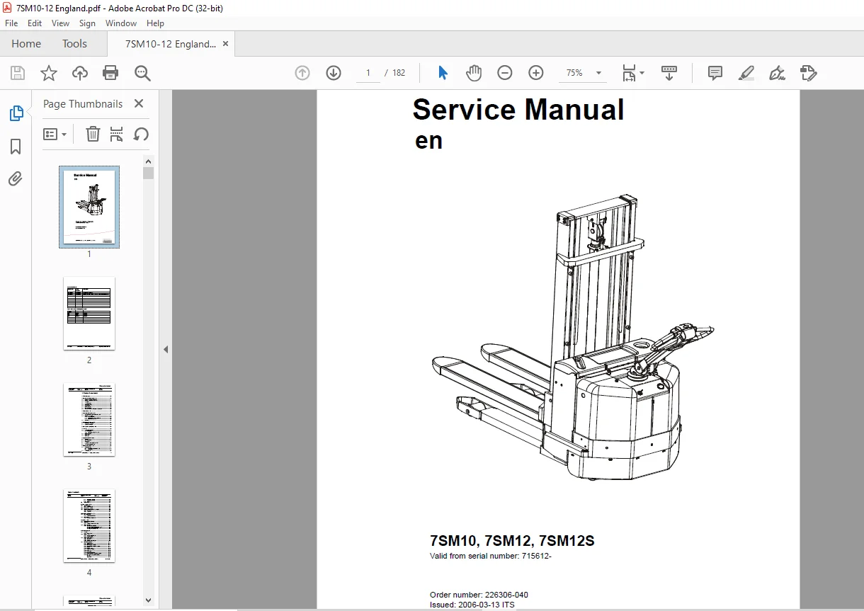
Toyota Forklift 7SM10 7SM12 7SM12S Service Manual SN 715612 – PDF DOWNLOAD
$27.95
Toyota Forklift 7SM10 7SM12 7SM12S Service Manual SN 715612 – PDF DOWNLOAD
Instant PDF Download
Available immediately
Save to Your Device
Download & keep forever
Antivirus Scanned
100% virus-free
Trusted Worldwide
175,000+ customers
Description
Toyota Forklift 7SM10 7SM12 7SM12S Service Manual SN 715612 – PDF DOWNLOAD
FILE DETAILS:
Toyota Forklift 7SM10 7SM12 7SM12S Service Manual SN 715612 – PDF DOWNLOAD
Language : English
Pages : 182
Downloadable : Yes
File Type : PDF
DESCRIPTION:
Toyota Forklift 7SM10 7SM12 7SM12S Service Manual SN 715612 – PDF DOWNLOAD
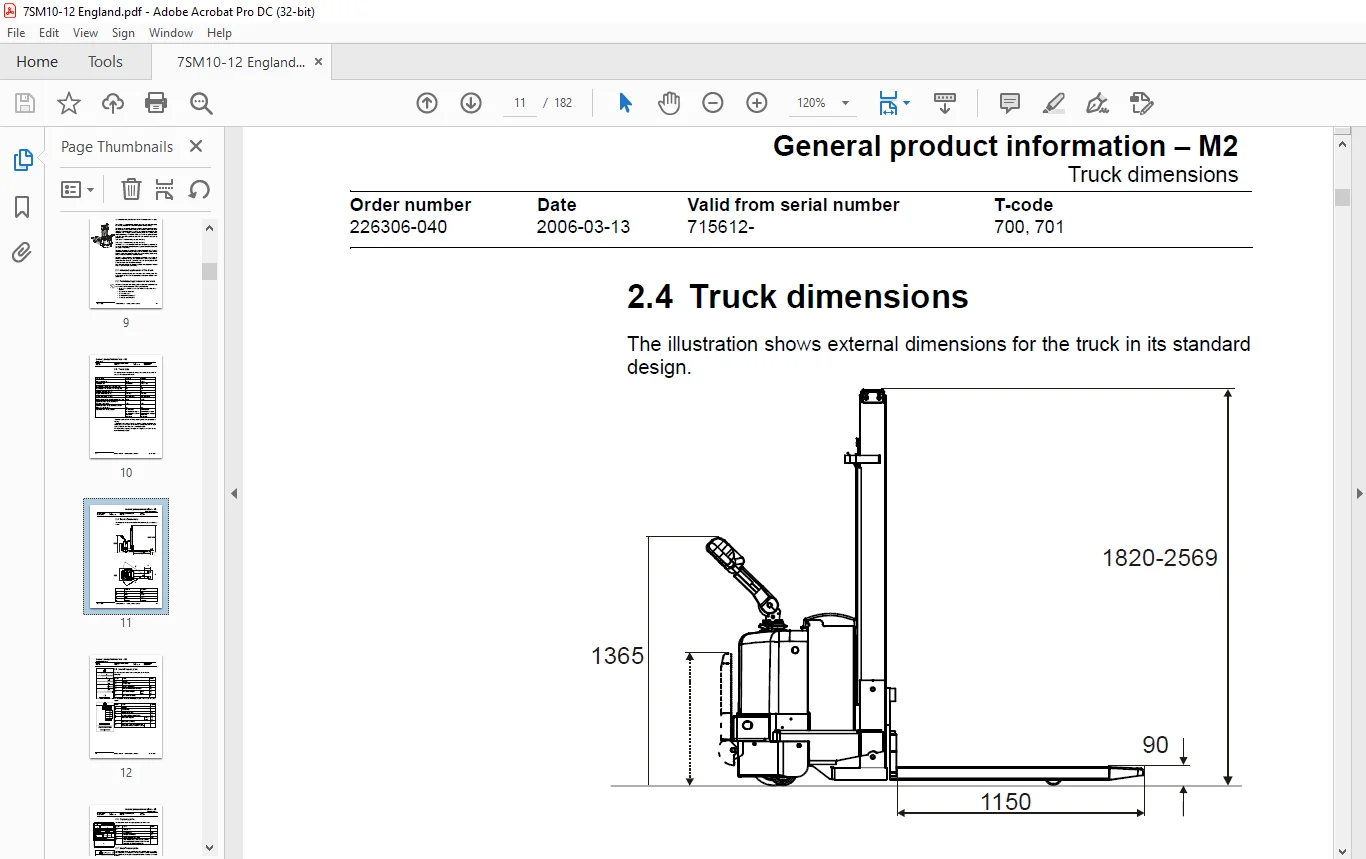
General product information – M2:
- The truck is a battery-powered support arm truck. In its standard design the truck is equipped with a tiller arm for control while walking.
- The tiller arm is specially designed to provide the best possible operator ergonomy, having all the controls and buttons within easy reach without the operator needing to release the handle. The tiller arm is also equipped with a display showing running time and battery status among other things. The display is also used when the operator wishes to change any of the operator parameters with which the truck can be programmed.
7SM10 has a maximum lifting capacity of 1000 kg.
7SM12 has a maximum lifting capacity of 1200 kg.
- The truck has a 24V electrical system and the speed is regulated by means of a transistor controller to provide gentle control of acceleration and speed while driving.
- The forks are raised by means of a powerful hydraulic unit. The lift is electrically controlled using the buttons on the tiller arm. Control of the lowering speed and positioning of the forks when stacking is performed using the truck’s mechanical hydraulic valves.
- The truck can be equipped with different accessories such as ride-on platform, integrated charger, load support and a button for temporary speed reduction. The truck can also be fitted with low temperature oil if it is to be used in cool and humid conditions.
- Note that some of the truck models described in the Operator’s Manual may not be marketed in your country.
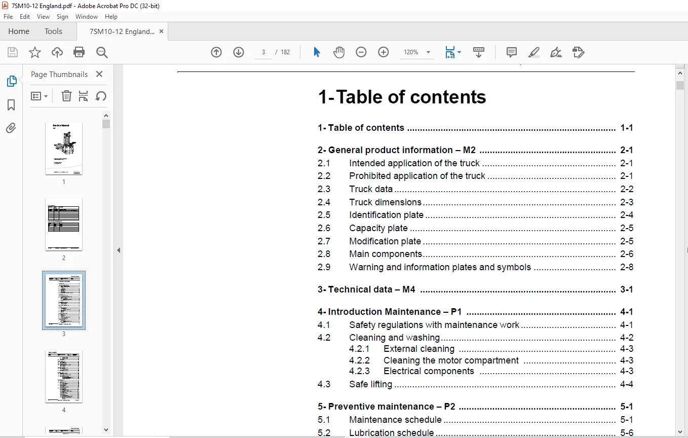
TABLE OF CONTENTS:
Toyota Forklift 7SM10 7SM12 7SM12S Service Manual SN 715612 – PDF DOWNLOAD
1- Table of contents................................................................................  3
2- General product information - M2.................................................................  9
	2.1 Intended application of the truck...........................................................  9
	2.2 Prohibited application of the truck.........................................................  9
	2.3 Truck data.................................................................................. 10
	2.4 Truck dimensions............................................................................ 11
	2.5 Identification plate........................................................................ 12
	2.6 Capacity plate.............................................................................. 13
	2.7 Modification plate.......................................................................... 13
	2.8 Main components............................................................................. 14
	2.9 Warning and information plates and symbols.................................................. 16
3- Technical data - M4.............................................................................. 19
4- Introduction Maintenance - P1.................................................................... 23
	4.1 Safety regulations with maintenance work.................................................... 23
	4.2 Cleaning and washing........................................................................ 24
		4.2.1 External cleaning..................................................................... 25
		4.2.2 Cleaning the motor compartment........................................................ 25
		4.2.3 Electrical components................................................................. 25
	4.3 Safe lifting................................................................................ 26
5- Preventive maintenance - P2...................................................................... 27
	5.1 Maintenance schedule........................................................................ 27
	5.2 Lubrication schedule........................................................................ 32
6- Oil and grease specification - P3................................................................ 35
7- Tools - P4....................................................................................... 37
	7.1 Super Seal connectors....................................................................... 37
	7.2 AMP connectors.............................................................................. 38
		7.2.1 AMP Connectors, 040 series............................................................ 39
	7.3 Molex connectors............................................................................ 39
	7.4 Grease guns................................................................................. 40
	7.5 Other tools................................................................................. 41
8- Support arm chassis - 0350....................................................................... 43
	8.1 General..................................................................................... 43
	8.2 Main components............................................................................. 44
	8.3 Maintenance................................................................................. 44
	8.4 Adjustment of the support arm width......................................................... 45
	8.5 Exchange of support arms.................................................................... 46
9- Electric drive motor - 1760...................................................................... 47
	9.1 Component parts............................................................................. 47
		9.1.1 Dismantling of motor from truck....................................................... 48
		9.1.2 Assembling............................................................................ 48
	9.2 Service/Repairs............................................................................. 49
		9.2.1 Dismantling of motor.................................................................. 49
		9.2.2 Assembling of motor................................................................... 50
		9.2.3 Cleaning.............................................................................. 50
	9.3 Technical data.............................................................................. 51
10- Drive unit/gear - 2550.......................................................................... 53
	10.1 Component parts............................................................................ 54
		10.1.1 Technical data....................................................................... 55
	10.2 Leakage from top cover..................................................................... 56
	10.3 Changing of the drive shaft’s sealing ring................................................. 56
		10.3.1 Dismantling.......................................................................... 56
		10.3.2 Assembling........................................................................... 57
11- Electro magnetic brake - 3370................................................................... 59
	11.1 Main components............................................................................ 59
		11.1.1 Serial number 570989-................................................................ 59
	11.2 Maintenance................................................................................ 60
		11.2.1 Exchange of brake disc............................................................... 60
12- Steering - 4000................................................................................. 61
	12.1 Component parts, tiller arm................................................................ 61
	12.2 Adjustments................................................................................ 62
		12.2.1 Adjusting of brake microswitch....................................................... 62
	12.3 Tiller arm handle.......................................................................... 63
		12.3.1 Dismantling/Assembling............................................................... 65
			Changing of signal button/switch (9, 10)................................................ 65
			Changing of lift/lowering button (13)................................................... 66
			Changing of pushbutton (16)............................................................. 66
13- Electrical systems.............................................................................. 67
	13.1 General.................................................................................... 67
		13.1.1 Part numbers......................................................................... 67
	13.2 Electrical parts........................................................................... 68
		13.2.1 Component placement.................................................................. 68
		13.2.2 Component list....................................................................... 70
	13.3 Electrical wiring diagram.................................................................. 72
		13.3.1 Symbol list.......................................................................... 72
		13.3.2 Overview............................................................................. 73
		13.3.3 Detailed wiring diagram.............................................................. 74
	13.4 Functional description..................................................................... 80
		13.4.1 Starting the truck................................................................... 80
		13.4.2 Driving.............................................................................. 80
		13.4.3 Neutral speed reduction.............................................................. 80
		13.4.4 Neutral speed reduction on slopes.................................................... 80
		13.4.5 Braking.............................................................................. 80
		13.4.6 Lifting the forks.................................................................... 81
		13.4.7 Lowering the forks................................................................... 81
		13.4.8 Horn................................................................................. 81
		13.4.9 Hour meter........................................................................... 81
		13.4.10 Transistor regulator................................................................ 81
		13.4.11 Spider expansion unit (SEU) (option)................................................ 82
		13.4.12 TLS - Truck log system (optional)................................................... 85
			General................................................................................. 85
			Registration............................................................................ 85
			Logging in/out SD16..................................................................... 85
			Logging in/out S16...................................................................... 85
			Collision sensor........................................................................ 86
			Settings................................................................................ 86
		13.4.13 ID unit (optional).................................................................. 87
			General................................................................................. 87
			Installation............................................................................ 87
			Settings................................................................................ 88
	13.5 Parameters................................................................................. 90
		13.5.1 General.............................................................................. 90
		13.5.2 Viewing parameters - without the CAN service key..................................... 90
		13.5.3 Adjusting operator parameters - without the CAN service key.......................... 91
		13.5.4 Viewing & changing parameters - CAN service key connected............................ 92
			Changing a parameter.................................................................... 93
		13.5.5 Operator parameters.................................................................. 94
		13.5.6 Parameter description................................................................ 94
			Parameter 1............................................................................. 94
			Parameter 2............................................................................. 94
			Parameter 3............................................................................. 94
			Parameter 4............................................................................. 94
			Parameter 5............................................................................. 95
		13.5.7 Service parameters................................................................... 96
		13.5.8 Parameter description................................................................ 97
			Parameter 10............................................................................ 97
			Parameter 14............................................................................ 97
			#15 - Non-configurable options.......................................................... 97
			Setting Non-configurable options........................................................ 97
			#16 - Configurable option #1............................................................ 98
			#17 - Configurable option #2............................................................ 98
			#18 - Configurable option #3............................................................ 98
			#19 - Configurable option #4............................................................ 98
			Parameter 20............................................................................ 99
			Parameter 21............................................................................ 99
			Recommendation on parameter setting for freely ventilated batteries.....................100
			Instructions for verifying parameter setting............................................101
			Recommendation on parameter setting for valve- controlled batteries (VRLA)..............102
			Instructions for verifying parameter setting............................................103
			Parameter 22............................................................................103
			Parameter 25............................................................................103
			Parameter 28............................................................................103
			Parameter 39............................................................................104
			Log-in method & operator parameter access...............................................104
			Expanded keypad - General...............................................................104
			Expanded keypad - Programming...........................................................104
		13.5.9 Configurable “Option” Parameters.....................................................107
			General.................................................................................107
			Summary of base options.................................................................107
			Convention for configurable options.....................................................108
			Detailed option parameter tables........................................................110
	13.6 Diagnostic and troubleshooting.............................................................121
		13.6.1 General..............................................................................121
		13.6.2 Error code history...................................................................121
		13.6.3 Fault codes..........................................................................122
		13.6.4 Transistor regulator errors..........................................................135
			Resetting errors........................................................................136
			Safety..................................................................................136
		13.6.5 Built-in Test Function...............................................................137
			Digital inputs/outputs test mode........................................................138
			Inputs check............................................................................138
			Outputs check...........................................................................139
			Option buttons check....................................................................140
			Display test mode.......................................................................140
	13.7 Technical specifications - Curtis 1243.....................................................141
14- Hydraulic system - 6000.........................................................................143
	14.1 General....................................................................................143
	14.2 Hydraulic diagram and components...........................................................143
		14.2.1 Main components......................................................................143
		14.2.2 Description..........................................................................144
			Lift....................................................................................144
			Lowering................................................................................144
			Operating pressure......................................................................144
			Relief valve............................................................................144
			Pressure switch.........................................................................144
15- Lifting Mast - 7000.............................................................................145
	15.1 Grease the beam flanges and beam ribs......................................................145
	15.2 Main lift chain system.....................................................................146
		15.2.1 General..............................................................................146
		15.2.2 Checking the chain setting...........................................................146
		15.2.3 Chain inspection.....................................................................146
		15.2.4 Noise................................................................................146
		15.2.5 Surface rust.........................................................................146
		15.2.6 Rusty links..........................................................................146
		15.2.7 Stiff links..........................................................................146
		15.2.8 Bolt rotation........................................................................147
		15.2.9 Loose bolts..........................................................................147
		15.2.10 Outline wear........................................................................148
		15.2.11 Stretching..........................................................................149
		15.2.12 Damage..............................................................................149
		15.2.13 Damaged discs.......................................................................150
		15.2.14 Damaged bolts.......................................................................150
		15.2.15 Dirty chain.........................................................................150
	15.3 Cleaning...................................................................................150
	15.4 Lubrication................................................................................151
16- Battery charger (built-in) - 8340...............................................................153
	16.1 General....................................................................................153
	16.2 Technical data - charger...................................................................154
	16.3 Charging...................................................................................154
		Machine numbers 723984-936512...............................................................154
		Machine numbers 936513-.....................................................................155
	16.4 Troubleshooting and service................................................................155
	16.5 Setting the charger (applies to machine numbers 723984-936512).............................156
		Freely ventilated batteries.................................................................156
		Valve-regulated batteries...................................................................156
		16.5.1 Current levels at different charger settings (applies to machine numbers 936513-)....157
			Freely ventilated batteries.............................................................157
			Valve-regulated batteries (Evolution type)..............................................158
17- Control/computer equipment - 8700...............................................................159
	17.1 General....................................................................................159
	17.2 Connection.................................................................................159
	17.3 Layout.....................................................................................160
		17.3.1 Main program screen..................................................................160
		17.3.2 Nodes................................................................................160
		17.3.3 Icons................................................................................161
		17.3.4 Tool buttons and menu bar............................................................162
		17.3.5 Information window...................................................................162
		17.3.6 Status bar...........................................................................162
	17.4 Connection function........................................................................163
	17.5 Disconnection function.....................................................................163
	17.6 Downloading program function...............................................................163
		17.6.1 Normal downloading (truck with key)..................................................164
		17.6.2 Normal downloading (truck with keypad)...............................................164
		17.6.3 Emergency downloading (truck with keypad)............................................164
		17.6.4 Downloading in old versions of logic card............................................165
		17.6.5 Emergency downloading (truck with keypad)............................................165
	17.7 Truck report function......................................................................166
	17.8 Parameters function........................................................................167
	17.9 Diagnostics function.......................................................................167
		17.9.1 Representation of signal colours.....................................................168
		17.9.2 “Tiller arm” tab.....................................................................168
		17.9.3 “Drive Controller” tab (transistor regulator - driving)..............................169
		17.9.4 “Pump controller” tab (transistor regulator - pump)..................................170
		17.9.5 “EPS” steering servo tab.............................................................171
	17.10 Other menu functions......................................................................172
		17.10.1 Save to file........................................................................172
		17.10.2 Download from file..................................................................172
		17.10.3 Reset CAN adapter...................................................................172
		17.10.4 Delete error code log...............................................................172
		17.10.5 Reset hour meter....................................................................172
		17.10.6 Read error code log.................................................................172
		17.10.7 Adjust date and time................................................................173
		17.10.8 Adjusting the hour meter on older cards.............................................173
		17.10.9 Help................................................................................173
			About the TruckCom application..........................................................173
		17.10.10 Exit...............................................................................173
	17.11 Specifications............................................................................173
	17.12 Installation..............................................................................174
		17.12.1 Installation on a PC with Windows® 95/98............................................174
		17.12.2 Installation on a PC with Windows XP/ 2000..........................................175
			Changes in Windows® Control Panel.......................................................178
		17.12.3 Installation on a PC with Windows NT................................................180
		17.12.4 In case of communication problems with CAN..........................................180
		17.12.5 To uninstall........................................................................180
IMAGES PREVIEW OF THE MANUAL:
Questions? Email us: [email protected]
PLEASE NOTE:
- This is the SAME manual used by the dealers to troubleshoot any faults in your vehicle. This can be yours in 2 minutes after the payment is made.
- Contact us at [email protected] should you have any queries before your purchase or that you need any other service / repair / parts operators manual.
S.V