Toyota Forklift 7SM12F 7SM16D Service Manual SN 551390AT – PDF DOWNLOAD
$28.95
Toyota Forklift 7SM12F 7SM16D Service Manual SN 551390AT – PDF DOWNLOAD
Description
Toyota Forklift 7SM12F 7SM16D Service Manual SN 551390AT – PDF DOWNLOAD
FILE DETAILS:
Toyota Forklift 7SM12F 7SM16D Service Manual SN 551390AT – PDF DOWNLOAD
Language : English
Pages : 110
Downloadable : Yes
File Type : PDF
DESCRIPTION:
Toyota Forklift 7SM12F 7SM16D Service Manual SN 551390AT – PDF DOWNLOAD
INTRODUCTION MAINTENANCE:
- All points in the service program should be carried out to attain the highest safety and the least possible downtime. The service intervals are only a guide and do not need to be followed to the letter.
- The operator may adapt them to local conditions, but it is important that the intervals comply with TOYOTA’s minimum requirements. The service intervals are based on the running times and can be adapted to most normal 8 hour shifts. The service interval may be shortened if the truck is used more frequently or in more demanding situations, e.g cold store, dusty or corrosive situations.
The following running times have been used when calculating the intervals:
– Day time: 08.00-17.00 (20 hr./week)
– 2-shifts: 06.00-14.00, 14.00-22.00 (40 hr./week)
– 3-shifts: 06.00-14.00, 14.00-22.00,22.00-06.00
(60 hr./week)
- Ensure the truck is given a regular maintenance service after every 500 driving hours. The truck’s safety, efficiency and service life is dependent on the service and maintenance it is given.
- Only use TOYOTA approved spare parts when service and repair work are carried out.
Safety Regulation with Maintenance work:
Only personnel that have been trained in the service and repair of this
type of truck are authorised to carry out service and repair work.
• Do not carry out any maintenance work on the truck unless you
have the correct training and knowledge to do so
• Keep the area where you carry out the service clean. Oil or water
makes the floor slippery
• Never wear loose objects or jewellery when working on the truck
TABLE OF CONTENTS:
Toyota Forklift 7SM12F 7SM16D Service Manual SN 551390AT – PDF DOWNLOAD
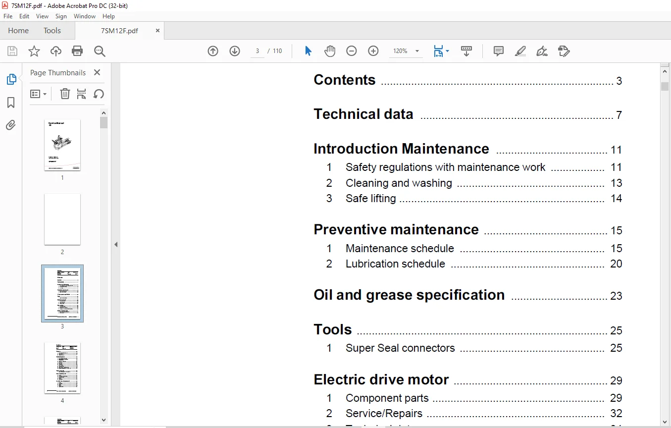
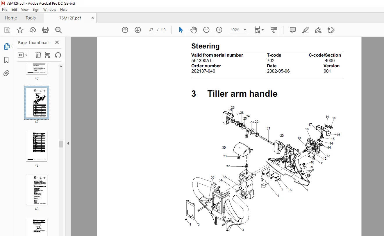
Contents.......................................................  3
	Contents 3.................................................  3
	Technical data 7...........................................  3
	Introduction Maintenance 11................................  3
	Preventive maintenance 15..................................  3
	Oil and grease specification 23............................  3
	Tools 25...................................................  3
	Electric drive motor 29....................................  3
	Drive unit/gear 35.........................................  3
	Electro magnetic brake 41..................................  3
	Steering 45................................................  4
	Electrical systems 53......................................  4
	Hydraulic system 83........................................  4
	Main lift chain system 87..................................  4
	Control/computer equipment 93..............................  4
	Battery charger (Inbuilt) 107..............................  5
Technical data.................................................  7
	Model......................................................  7
	7SM12F.....................................................  7
	7SM16D.....................................................  7
Introduction Maintenance....................................... 11
	1 Safety regulations with maintenance work................. 11
		WARNING!............................................... 11
		WARNING!............................................... 12
		WARNING!............................................... 12
		NOTE!.................................................. 12
		CAUTION!............................................... 12
	2 Cleaning and washing..................................... 13
		NOTE!.................................................. 13
		2.1 External cleaning.................................. 13
			NOTE!.............................................. 13
		2.2 Cleaning the motor compartment..................... 13
			NOTE!.............................................. 13
		2.3 Electrical components.............................. 14
			NOTE!.............................................. 14
	3 Safe lifting............................................. 14
		WARNING!............................................... 14
Preventive maintenance......................................... 15
	1 Maintenance schedule..................................... 15
		Pos. No................................................ 15
		Work to carry out...................................... 15
	2 Lubrication schedule..................................... 20
		Pos no................................................. 20
		Service point.......................................... 20
		Interval/Running hours................................. 20
		Lubricant.............................................. 20
Oil and grease specification................................... 23
	Lubticant.................................................. 23
	Specification.............................................. 23
	Application area........................................... 23
Tools.......................................................... 25
	1 Super Seal connectors.................................... 25
		Figure................................................. 25
		Number................................................. 25
		Application............................................ 25
		1.1 AMP connectors..................................... 26
			Figure............................................. 26
			Number............................................. 26
			Application........................................ 26
		1.2 Other tools........................................ 27
			Figure............................................. 27
			Number............................................. 27
			Application........................................ 27
Electric drive motor........................................... 29
	1 Component parts.......................................... 29
		Pos.................................................... 29
		Description............................................ 29
		Note................................................... 29
		1.1 Dismantling of motor from truck.................... 30
		1.2 Assembling......................................... 31
	2 Service/Repairs.......................................... 32
		2.1 Dismantling of motor............................... 32
		2.2 Assembling of motor................................ 33
		2.3 Cleaning........................................... 33
	3 Technical data........................................... 34
		Type of machine........................................ 34
		7SM12F, 7SM16D......................................... 34
Drive unit/gear................................................ 35
	1 Component parts.......................................... 36
		Pos.................................................... 36
		Description............................................ 36
		Note................................................... 36
		1.1 Technical data..................................... 37
			Type of truck...................................... 37
			7SM12F, 7SM16D..................................... 37
	2 Leakage from top cover................................... 38
	3 Changing of the drive shaft’s sealing ring............... 38
		3.1 Dismantling........................................ 38
		3.2 Assembling......................................... 39
Electro magnetic brake......................................... 41
	1 Main components of the brake............................. 41
	2 Maintenance.............................................. 42
		2.1 Basic Adjustment of gap............................ 42
		2.2 Exchange of brake disc............................. 43
Steering....................................................... 45
	1 Component parts, tiller arm.............................. 45
		Pos.................................................... 45
		Description............................................ 45
		Note................................................... 45
	2 Adjustments.............................................. 46
		2.1 Adjusting of brake microswitch..................... 46
	3 Tiller arm handle........................................ 47
		Pos.................................................... 47
		Description............................................ 47
		Note................................................... 47
		3.1 Dismantling/Assembling............................. 49
			NOTE!.............................................. 49
			Change from ignition key to keyboard (2)........... 49
			Change from keyboard to ignition key (2)........... 49
			Changing of signal button/switch (9, 10)........... 50
			Changing of lift/lowering button (13).............. 51
			Changing of pushbutton (16)........................ 51
Electrical systems............................................. 53
	1 Component identification................................. 53
	2 List of symbols and electrical wiring diagram............ 55
		Symbol................................................. 55
		Description............................................ 55
		Function............................................... 55
		Notes.................................................. 55
		2.1 Electrical diagram 1(5)............................ 57
		2.2 Electrical diagram 2(5)............................ 58
		2.3 Electrical diagram 3(5)............................ 59
		2.4 Electrical diagram 4(5)............................ 60
		2.5 Electrical diagram 5(5)............................ 61
	3 Functional description................................... 62
		3.1 Starting the truck................................. 62
		3.2 Driving............................................ 62
		3.3 Neutral speed reduction............................ 62
		3.4 Picture 3.......................................... 62
		3.5 Neutral speed reduction on slopes.................. 63
		3.6 Braking............................................ 63
		3.7 Lifting the forks.................................. 63
		3.8 Lifting the support arms........................... 63
		3.9 Lowering the forks................................. 63
		3.10 Lowering the support arms......................... 63
		3.11 Horn.............................................. 63
	4 Hour meter............................................... 64
	5 Fault codes.............................................. 64
		Code................................................... 65
		C19.................................................... 65
		Code................................................... 65
		C20.................................................... 65
		Code................................................... 65
		C28.................................................... 65
		Code................................................... 65
		C29.................................................... 65
		Code................................................... 65
		C41.................................................... 65
		Code................................................... 66
		C42.................................................... 66
		Code................................................... 66
		C43.................................................... 66
		Code................................................... 66
		E101................................................... 66
		Code................................................... 66
		E104................................................... 66
		Code................................................... 66
		E106................................................... 66
		Code................................................... 67
		E107................................................... 67
		Code................................................... 67
		E108................................................... 67
		Code................................................... 67
		E110................................................... 67
		Code................................................... 67
		E140................................................... 67
		Code................................................... 67
		E141................................................... 67
		Code................................................... 67
		E150................................................... 67
		Code................................................... 68
		E151................................................... 68
		Code................................................... 68
		E157................................................... 68
		Code................................................... 68
		E159................................................... 68
		Code................................................... 68
		E160................................................... 68
		Code................................................... 68
		E200................................................... 68
		Code................................................... 68
		E201................................................... 68
		Code................................................... 69
		E202................................................... 69
		Code................................................... 69
		E214................................................... 69
	6 Parameters............................................... 69
		NOTE !................................................. 69
		6.1 Driver parameters.................................. 70
			Parameter.......................................... 70
			Name............................................... 70
			Unit............................................... 70
			Min................................................ 70
			Max................................................ 70
			Step............................................... 70
			Std................................................ 70
			Description........................................ 70
		6.2 Service parameters................................. 71
			Parameter.......................................... 71
			Name............................................... 71
			Unit............................................... 71
			Min................................................ 71
			Max................................................ 71
			Step............................................... 71
			Std................................................ 71
			Description........................................ 71
		6.3 Parameter description.............................. 72
			Parameter 1........................................ 72
			Parameter 2........................................ 72
			Parameter 3........................................ 72
			Parameter 4........................................ 72
			Parameter 5........................................ 72
			Parameter 10....................................... 72
			Parameter 14....................................... 72
			Parameter 20....................................... 73
			Parameter 21....................................... 73
				Value.......................................... 74
				Function....................................... 74
				Battery (Ah)................................... 74
				WARNING !...................................... 74
			Parameter 25....................................... 74
			Parameter 28....................................... 75
			Parameter 39....................................... 75
			Service display.................................... 75
				Flashing symbol................................ 76
				Displayed data................................. 76
				Segment........................................ 76
				Function....................................... 76
				Segment........................................ 77
				Function....................................... 77
				Segment........................................ 77
				Function....................................... 77
				Segment........................................ 78
				Function....................................... 78
	7 Part numbers............................................. 78
	8 Transistor panel......................................... 79
		8.1 General............................................ 79
	9 Diagnostic and troubleshooting........................... 80
		9.1 Error codes and troubleshooting.................... 80
			STATUS LED......................................... 80
			Handheld terminal display.......................... 80
			Explanation........................................ 80
			Possible cause..................................... 80
		9.2 Resetting errors................................... 81
			Error.............................................. 81
			Reset when......................................... 81
		9.3 Safety............................................. 81
			WARNING!........................................... 81
	10 Technical specifications – Curtis 1243.................. 82
		Value.................................................. 82
		Unit................................................... 82
		Explanation............................................ 82
Hydraulic system............................................... 83
	1 Hydraulic diagram and components......................... 83
		1.1 Main components.................................... 83
			Pos No............................................. 83
			Description........................................ 83
			Remark............................................. 83
		1.2 Description........................................ 84
			1.2.1 Lift......................................... 84
			1.2.2 Lowering..................................... 84
			1.2.3 Operating pressure........................... 84
			1.2.4 Relief valve................................. 84
			1.2.5. Pressure switch............................. 85
Main lift chain system......................................... 87
	2 General.................................................. 87
	3 Checking the chain setting............................... 87
	4 Chain inspection......................................... 87
		4.1 Noise.............................................. 87
		4.2 Surface rust....................................... 87
		4.3 Rusty links........................................ 87
		4.4 Stiff links........................................ 88
		4.5 Bolt rotation...................................... 88
		4.6 Loose bolts........................................ 88
		4.7 Outline wear....................................... 89
		4.8 Stretching......................................... 90
		4.9 Damage............................................. 90
		4.10 Damaged discs..................................... 91
		4.11 Damaged bolts..................................... 91
		4.12 Dirty chain....................................... 91
	5 Cleaning................................................. 91
		NOTE!.................................................. 91
	6 Lubrication.............................................. 92
		NOTE!.................................................. 92
		NOTE!.................................................. 92
Control/computer equipment..................................... 93
	1 General.................................................. 93
	2 Connection............................................... 93
	3 Layout................................................... 94
		3.1 Main window........................................ 94
		3.2 Nodes.............................................. 94
			3.2.1 Icons........................................ 95
				Icon........................................... 95
				Description.................................... 95
		3.3 Tool buttons....................................... 95
		3.4 Information window................................. 96
		3.5 Status bar......................................... 96
	4 Function................................................. 96
		4.1 Connection......................................... 96
		4.2 Disconnection...................................... 97
		4.3 Downloading program................................ 97
			4.3.1 Normal downloading........................... 98
			4.3.2 Downloading in old versions of logic card.... 98
			4.3.3 Emergency downloading........................ 98
				NOTE!.......................................... 98
		4.4 Truck report....................................... 99
		4.5 Parameters.........................................100
			NOTE!..............................................100
		4.6 Diagnostics........................................101
			NOTE!..............................................101
			4.6.1 Analogue.....................................101
			4.6.2 Temperature..................................102
				NOTE!..........................................102
			4.6.3 Digital......................................102
		4.7 Other functions....................................103
			4.7.1 Save to file.................................103
			4.7.2 Download from file...........................103
			4.7.3 Reset CAN adapter............................103
			4.7.4 Delete error code log........................103
			4.7.5 Reset hour meter.............................103
			4.7.6 Read error code log..........................103
			4.7.7 Adjust date and time.........................103
				NOTE!..........................................103
			4.7.8 Adjusting the hour meter on older cards......104
		4.8 Help...............................................104
			4.8.1 About TruckCom...............................104
		4.9 Exit...............................................104
	5 Specifications...........................................104
		5.1 CAN interface......................................104
		5.2 Installation.......................................105
		5.3 To uninstall.......................................105
Battery charger (Inbuilt)......................................107
	1 General..................................................107
	2 Charging.................................................107
	3 Troubleshooting and service..............................108
	4 Technical data...........................................108
	5 Charging settings........................................109
		5.1 Freely ventilated batteries........................109
			Switch.............................................109
			Batterysize........................................109
			Output current.....................................109
			I2 current.........................................109
			Max current maintenance............................109
		5.2 Valve regulated batteries..........................109
			Switch.............................................109
			Batterysize........................................109
			Output current.....................................109
			I2 current.........................................109
			Max current maintenance............................109
IMAGES PREVIEW OF THE MANUAL:
Need help? Contact: [email protected]
PLEASE NOTE:
- This is the same manual used by the DEALERSHIPS to SERVICE your vehicle.
- The manual can be all yours – Once payment is complete, you will be taken to the download page from where you can download the manual. All in 2-5 minutes time!!
- Need any other service / repair / parts manual, please feel free to contact us at heydownloadss @gmail.com . We may surprise you with a nice offer
S.V