Toyota Trucks 8HBW30 8HBE30 8HBE40 8HBC30 8HBC40 8TB50 Service Manual – PDF DOWNLOAD
Original price was: $78.95.$32.95Current price is: $32.95.
Toyota Trucks 8HBW30 8HBE30 8HBE40 8HBC30 8HBC40 8TB50 Service Manual – PDF DOWNLOAD
Description
Toyota Trucks 8HBW30 8HBE30 8HBE40 8HBC30 8HBC40 8TB50 Service Manual – PDF DOWNLOAD
FILE DETAILS:
Toyota Trucks 8HBW30 8HBE30 8HBE40 8HBC30 8HBC40 8TB50 Service Manual – PDF DOWNLOAD
Size : 12.6 MB
Format : PDF
Language : English
Number of Pages: 257 Pages
DESCRIPTION:
Toyota Trucks 8HBW30 8HBE30 8HBE40 8HBC30 8HBC40 8TB50 Service Manual – PDF DOWNLOAD
MANUAL DESIGN:
The Toyota Reach Service Manual is designed with the following objectives in mind:
- Provide technical coverage for expected levels of user expertise.
- Anticipate your needs and reduce your decisions regarding maintenance.
- Reduce page flipping through a “one-stop shopping” approach.
The two—line running page header at the top of each page tells you:
- the name of the manual (Toyota Reach Service Manual)
- the current Chapter Title (e.g.. this page How to Use This Manual)
- the current topic (e.g., this page Marmal Design)
- We suggest you get in the habit of turning to the START page first when you use this manual.
- The START page asks a few simple questions to guide you to the proper chapter.
- How to Use This Manual explains the manual format and design and contains the Table of Contents and START page.
- Safety explains warning and caution notes, general safety rules and safety rules for batteries, static, jacking, and welding.
- Systems Overview includes truck specifications and functional overview of the major systems.
- Scheduled Maintenance outlines the recommended schedule of preventive services to keep your truck working most efficiently.
- Troubleshooting is a set of “decision-tree” charts designed to take you from a symptom to a specific sequence of tests in order to isolate a failing component.
- The START TROUBLESHOOTING chart (on page 5—20) will guide you to the individual troubleshooting symptom chart you need.
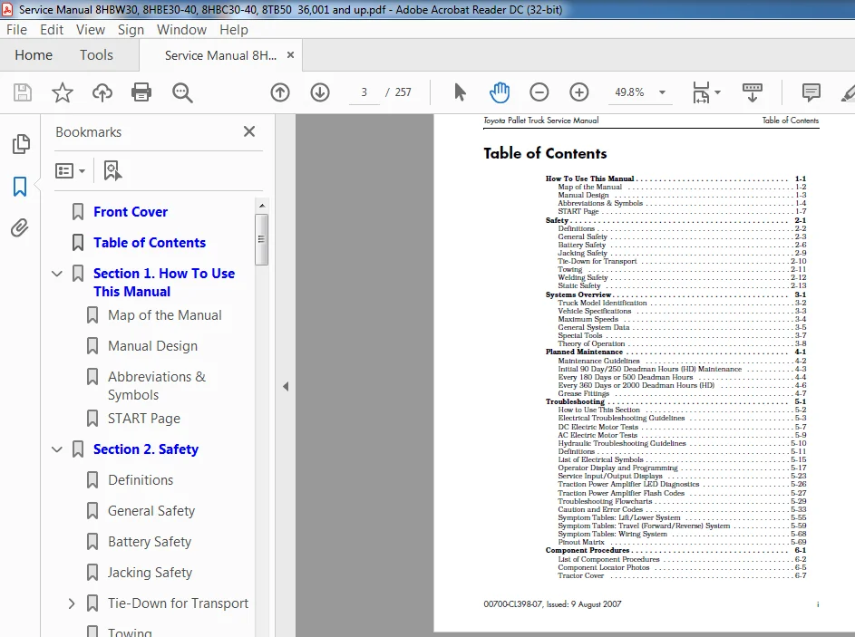
TABLE OF CONTENTS:
Toyota Trucks 8HBW30 8HBE30 8HBE40 8HBC30 8HBC40 8TB50 Service Manual – PDF DOWNLOAD
How To Use This Manual 1-1
Map of the Manual 1-2
Manual Design1-3
Abbreviations & Symbols1-4
START Page 1-7
Safety 2-1
Definitions 2-2
General Safety 2-3
Battery Safety 2-6
Jacking Safety 2-9
Tie-Down for Transport2-10
Towing 2-11
Welding Safety2-12
Static Safety 2-13
Systems Overview 3-1
Truck Model Identification 3-2
Vehicle Specifications 3-3
Maximum Speeds 3-4
General System Data 3-5
Special Tools 3-7
Theory of Operation 3-8
Planned Maintenance 4-1
Maintenance Guidelines4-2
Initial 90 Day/250 Deadman Hours (HD) Maintenance 4-3
Every 180 Days or 500 Deadman Hours 4-4
Every 360 Days or 2000 Deadman Hours (HD) 4-6
Grease Fittings4-7
Troubleshooting 5-1
How to Use This Section5-2
Electrical Troubleshooting Guidelines 5-3
DC Electric Motor Tests 5-7
AC Electric Motor Tests 5-9
Hydraulic Troubleshooting Guidelines 5-10
Definitions 5-11
List of Electrical Symbols 5-15
Operator Display and Programming 5-17
Service Input/Output Displays 5-23
Traction Power Amplifier LED Diagnostics5-26
Traction Power Amplifier Flash Codes 5-27
Troubleshooting Flowcharts 5-29
Caution and Error Codes 5-33
Symptom Tables: Lift/Lower System 5-55
Symptom Tables: Travel (Forward/Reverse) System5-59
Symptom Tables: Wiring System5-68
Pinout Matrix5-69
Component Procedures6-1
List of Component Procedures 6-2
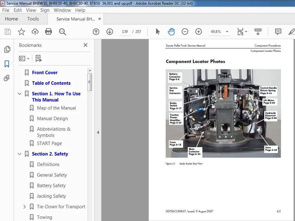
Component Locator Photos 6-5
Tractor Cover 6-7
Table of Contents Toyota Pallet Truck Service Manual
ii 00700-CL398-07, Issued: 9 August 2007
Battery 6-8
Power Cables6-11
Wiring Harness 6-12
Fuses 6-14
Switches (General) 6-15
Key Switch (SW1) 6-16
Brake (Deadman) Switch (SW2) 6-17
Lift-Limit Switch (SW8)6-19
Grab Rail Switches 6-20
Hydraulic Solenoids 6-21
Jog Pick Solenoid 6-22
Horn6-24
Traction Power Amplifier 6-25
AMP Harness/Traction Power Amplifier Connector6-27
Contactors 6-30
Control Handle Assembly 6-33
Control Handle 6-36
Brake 6-41
Motors, General 6-45
Traction Motor 6-46
AC Motor Service 6-49
Drive Unit 6-51
Drive Wheel 6-60
Casters (Torsion) 6-63
Casters (Spring-Loaded) 6-65
Load Wheels 6-69
Pallet Entry Sliders 6-72
Fork Height Adjustment 6-73
Hydraulic Components6-75
Hydraulic Fluid 6-76
Adjusting Hydraulic Pump Relief Valve Pressure 6-77
Hydraulic Ram 6-79
Hydraulic Unit 6-85
Lift Motor 6-89
Cold Storage Conditioning 6-91
Appendix A-1
Lubrication Equivalency Chart A-2
Torque Chart – Standard (Ferrous) A-3
Torque Chart – Standard (Brass) A-4
Torque Chart – Metric A-5
Torque Chart – Thread-Forming Screws A-6
Decimal Equivalent Chart A-7
Standard/Metric Conversions A-9
Electrical Schematics B-1
IndexI-1
TOYOTA TRUCKS 8HBW30 8HBE30 8HBE40 8HBC30 8HBC40 8TB50 SERVICE MANUAL – PDF DOWNLOAD:
IMAGES PREVIEW OF THE MANUAL:
PLEASE NOTE:
- This is the SAME exact manual used by your dealers to fix your vehicle.
- The same can be yours in the next 2-3 mins as you will be directed to the download page immediately after paying for the manual.
- Any queries / doubts regarding your purchase, please feel free to contact [email protected]