Twin Disc MG-5114SC MG-5114SC-HD Marine Transmission Service Manual PDF
Original price was: $95.00.$18.95Current price is: $18.95.
Complete Twin Disc factory service manual for MG-5114SC and MG-5114SC-HD marine transmissions with detailed repair procedures, hydraulic diagrams, disassembly/assembly instructions, and troubleshooting guides. Covers multiple gear ratios (0.93:1 through 3.00:1), manual and electronic control valves including GP valve, PX-10285 electric valve, and trolling valve options. Essential documentation for marine mechanics servicing pleasure craft and commercial vessel transmissions with torque specifications and parts lists.
Description
Twin Disc MG-5114SC MG-5114SC-HD Marine Transmission Service Manual PDF DOWNLOAD
DESCRIPTION
Twin Disc MG-5114SC / MG-5114SC-HD Marine Transmission – Complete Factory Service Manual
This comprehensive Twin Disc marine transmission service manual provides complete technical documentation for servicing, diagnosing, and repairing the MG-5114SC (aluminum housing) and MG-5114SC-HD (heavy-duty cast iron housing) marine transmissions. This professional-grade manual is the official Twin Disc factory documentation used by authorized marine service centers worldwide.
📋 FILE DETAILS
| Specification | Details |
|---|---|
| Manual Name | Twin Disc Marine Transmission Service Manual |
| Models Covered | MG-5114SC, MG-5114SC-HD |
| Document Number | 1021346 |
| Publication Date | July 2005 (Updated March 2019) |
| Total Pages | 281 pages |
| PDF Quality | Excellent – Factory original documentation |
| File Format | PDF (Letter size, searchable) |
| File Size | 9.2 MB |
| Manufacturer | Twin Disc, Incorporated |
⚙️ TRANSMISSION SPECIFICATIONS
Model MG-5114SC:
- Housing Material: Aluminum alloy main housing
- Application: Marine pleasure craft
- Design: Reverse and integral reduction transmission
- Gearing: Helical gears for quiet operation
Model MG-5114SC-HD:
- Housing Material: Cast iron main housing (heavy-duty)
- Application: Commercial marine and heavy-duty pleasure craft
- Design: Reverse and integral reduction transmission
- Gearing: Helical gears for quiet operation
Available Gear Ratios:
- 0.93:1
- 1.02:1
- 1.12:1
- 1.50:1
- 1.74:1
- 2.04:1
- 2.54:1
- 3.00:1
Key Features:
- Hydraulic Control: Complete hydraulic operation
- Dual Clutch System: Primary and secondary clutches
- Taper Roller Bearings: Shimmed for precise endplay adjustment
- SAE 1 Housing: Integral mounting flange
- Oil Pump Drive: Tang-connected, driven by secondary clutch shaft
- Reversible Rotation: Adaptable to RH or LH engine rotation
📖 COMPLETE TABLE OF CONTENTS
SECTION 1: INTRODUCTION (Pages 11-15)
- General Information
- Product overview
- Manual usage guidelines
- Safety and General Precautions
- Operating safety requirements
- Service safety procedures
- Preventative Maintenance Overview
- Scheduled maintenance importance
- Service intervals
- Backdriving or Towing Procedures
- Safe towing guidelines
- Transmission protection during towing
- Ordering Parts and Obtaining Services
- Parts identification procedures
- Authorized service network
- Source of Service Information
- Technical support resources
- Warranty Information
- Exclusive limited warranty details
- 36-month/24-month service warranty
- Warranty terms and conditions
- Flat rate hour allowances for all MG models
SECTION 2: DESCRIPTION AND SPECIFICATIONS (Pages 17-29)
- 2.1: General Description
- Transmission design overview
- Nameplate identification (Model, BOM, Serial Number)
- 2.2: Power Ratings
- Rated horsepower specifications
- Primary and secondary shaft ratings
- BOM/Specification number reference
- 2.3: Changing Rotation
- RH to LH rotation conversion procedures
- Pump repositioning instructions
- Engine rotation plate installation
- 2.4: Direction of Drive
- Power flow explanation
- Primary clutch engagement (anti-engine direction output)
- Secondary clutch engagement (engine direction output)
- 2.5: Construction Features
- One-piece main housing design
- Integral SAE 1 housing
- Aluminum rear bearing carrier
- Aluminum manifold construction
- Taper roller bearing specifications
- Oil pump drive configuration
- 2.6: Lubrication Features
- Hydraulic lubrication system
- Oil flow paths
- 2.7: Specifications
- Complete technical specifications
- Dimensional data
- Weight specifications
- 2.8: Optional Equipment
- Available options and upgrades
- 2.9: Assembly Specifications
- Critical assembly measurements
- Clearance specifications
- Endplay adjustments
- 2.10: Torque Values for Fasteners
- Complete torque specification tables
- Fastener grade requirements
SECTION 3: OPERATION (Pages 31-69)
- 3.1: General Operation Overview
- 3.2: Hydraulic System with Manual Control Valve
- Manual valve operation principles
- Hydraulic circuit description
- Pressure specifications
- 3.3: GP Control Valve with Electronic Interface
- General overview of GP control system
- Hydraulic portion operation
- Electronic control interface (Profile or E-Troll Module)
- Module programming and setup
- 3.4: Hydraulic System with GP Control Valve
- Complete system operation
- Troubleshooting interface
- 3.5: PX-10285 Electric Control Valve
- General overview
- Hydraulic operation principles
- Electronic control features
- 3.6: Optional 1018084 Electric Control Valve
- Hydraulic system operation
- Electric valve control
- 3.7: Trolling Valve (Optional)
- Trolling speed control operation
- Adjustment procedures
- 3.8: Power Take-Off (Optional)
- PTO operation and applications
- 3.9: Trailing Pump (Optional)
- Auxiliary pump operation
- 3.10: Power Flow
- Complete power flow diagrams
- Clutch engagement sequences
SECTION 4: PREVENTATIVE MAINTENANCE (Pages 71-75)
- 4.1: In-Boat Maintenance and Repair
- Service procedures without removal
- Access requirements
- 4.2: General Maintenance
- Routine maintenance schedules
- Fluid level checks
- Filter service
- Heat exchanger maintenance
- 4.3: Periodic Visual Inspection
- Inspection checklists
- Leak detection
- Component condition assessment
SECTION 5: TROUBLESHOOTING (Pages 77-83)
- 5.1: Troubleshooting with Manual/Standard Valves
- Symptom-based diagnosis
- Hydraulic pressure testing
- Component testing procedures
- 5.2: Troubleshooting GP Control Valve with Electronic Interface
- Electronic interface LED indicators
- Error code interpretation
- Diagnostic procedures
- Module troubleshooting
SECTION 6: DISASSEMBLY (Pages 85-141)
- 6.1: Prepare Transmission for Disassembly
- Pre-disassembly procedures
- Drain fluids
- Cleanliness requirements
- 6.2: Prior to Removal
- Documentation requirements
- Measurement recording
- 6.3: Removal of External Parts
- Step-by-step external component removal
- Control valve removal
- Pump removal
- Heat exchanger removal
- 6.4: Internal Subassemblies
- Top cover removal
- Clutch assembly removal
- Shaft removal procedures
- 6.5: Disassembly of Housings
- Main housing disassembly
- Bearing carrier separation
- 6.6: Disassembly of Primary Clutch
- Complete clutch pack disassembly
- Piston removal
- Seal replacement procedures
- 6.7: Disassembly of Secondary Clutch
- Secondary clutch service
- Component identification
- 6.8: Disassembly of Selector Valve – Mechanical Valve
- Manual valve disassembly
- Spool removal
- Spring specifications
- 6.9: Disassembly of GP Control Valve with Electronic Interface
- Complete GP valve disassembly procedures
- Electronic module removal
- Solenoid service
- 6.10: Disassembly of PX-10225 Electric Control Valve
- Electric valve disassembly
- Component inspection
- 6.11: Disassembly of 1018084 Electric Control Valve
- Upper valve body half (electric section)
- Lower valve body service
- 6.12: Disassembly of Trolling Valve (Optional Equipment)
- Trolling valve service procedures
SECTION 7: CLEANING AND INSPECTION (Pages 143-147)
- 7.1: Cleaning Procedures
- Recommended cleaning solvents
- Parts washing procedures
- Bearing cleaning
- 7.2: Inspection
- Visual inspection criteria
- Measurement procedures
- Wear limit specifications
- Clutch disc inspection
- Bearing inspection
- Gear tooth inspection
- Seal inspection
SECTION 8: ASSEMBLY (Pages 149-211)
- 8.1: Prior to Assembly
- Parts preparation
- Lubrication requirements
- Sealant application
- 8.2: Assembly of Main Housing
- Housing preparation
- Seal installation
- 8.3: Assembly of the Manifold
- Manifold assembly procedures
- Gasket installation
- 8.4: Assembly of Primary Clutch
- Clutch pack assembly
- Piston installation
- Seal installation
- Snap ring installation
- 8.5: Assembly of Secondary Clutch
- Secondary clutch rebuild
- Adjustment procedures
- 8.6: Assembly of Output Shaft
- Bearing installation
- Gear installation
- Endplay adjustment
- 8.7: Installation of Clutch Assemblies
- Primary clutch installation
- Secondary clutch installation
- Alignment procedures
- 8.8: Installation of External Parts
- Pump installation
- Heat exchanger installation
- Top cover installation
- Control valve installation
- 8.9: Assembly of Mechanical Control Valve
- Manual valve assembly
- Adjustment procedures
- 8.10: Assembly of GP Control Valve with Electronic Interface
- GP valve rebuild procedures
- Electronic module installation
- Solenoid installation
- 8.11: Adjustment of Main Pressure
- Pressure adjustment procedures
- Test specifications
- 8.12: Assembly of PX-10225 Electric Control Valve
- Electric valve assembly
- 8.13: Assembly of 1018084 Electric Control Valve
- Complete assembly procedures
- 8.14: Assembly of Trolling Valve (Optional Equipment)
- Trolling valve assembly
SECTION 9: INSTALLATION (Pages 213-231)
- 9.1: Prior to Installation
- Pre-installation checks
- Mounting preparation
- 9.2: Alignment (SAE J-1033 and J-617 Reference)
- Alignment procedures
- Tolerance specifications
- Dial indicator setup
- Coupling alignment
- 9.3: Electrical Controls
- Control harness routing
- Wiring guidelines
- Connector identification
- 9.4: Wiring Connections for Optional GP Control Valve
- Complete wiring diagrams
- Pin assignments
- Module connections
- 9.5: Final Checks
- Installation verification
- Fluid filling procedures
- Initial startup procedures
SECTION 10: SPECIAL TOOLS (Pages 233-244)
Complete Special Tool Catalog with Part Numbers:
- T-18503 Release Spring Compressor – Clutch spring compression
- TD-300389 Output Flange Puller – Flange removal tool
- TD-300427 Output Gear Press Sleeve – Gear installation
- TD-300428 Output Bearing Support – Bearing service tool
- TD-300429 Pinion Clamp (Secondary Shaft) – Shaft holding fixture
- TD-300432 Clutch Lifting Tool – Safe clutch handling
- TD-300451 Special Bearing Cup Races – Bearing service
- TD-300454 Expansion Plug Installation (Bearing Carrier) – Plug installer
- TD-300456 Seal Installation (Input) – Input seal installer
- TD-300461 Front Bearing Cone Installation – Bearing installer
- TD-300464 Bearing Cup Installation – Cup installation tool
Each tool includes detailed illustration and usage instructions
SECTION 11: ILLUSTRATIONS (Pages 245-256)
- MG-5114SC Transmission – Cross Section
- Primary Clutch Shaft – Cross Section
- Secondary Clutch Shaft – Cross Section
- Primary Clutch Shaft – Exploded View
- Secondary Shaft – Exploded View
- Output Shaft – Cross Section
- Housing Group – Cross Section
SECTION 12: ENGINEERING DRAWINGS (Pages 257-280)
Complete Engineering Drawing Package:
- PX-9785B (9 sheets) MG-5114SC
- Cross sections
- Installation dimensions
- Mounting specifications
- PX-11962 (8 sheets) MG-5114SC-HD
- Cross sections
- Installation dimensions
- Heavy-duty specifications
- PX-9975 Mechanical Control Valve Assembly
- PX-10225 Electric Control Valve Assembly
- 1018084 Electric Control Valve Assembly
- 1020729 GP Valve Assembly
- 1021658 GP Valve Assembly
- 1020583 E-Troll Control Module (2 sheets)
- 1020585 Profile Control Module (2 sheets)
- A7119J Hydraulic Diagram – Complete system schematic
⚡ KEY TECHNICAL FEATURES COVERED
Transmission Design:
- Helical Gearing – Quiet operation
- Reverse and Reduction – Integral design
- Dual Clutch System – Primary and secondary clutches
- Multiple Gear Ratios – 8 available ratios from 0.93:1 to 3.00:1
- Taper Roller Bearings – Precision shimmed bearings
- One-Piece Housing – Rigid construction
Control Systems:
- Manual Control Valve – Mechanical shift control
- GP Control Valve – Electronic interface with Profile or E-Troll modules
- PX-10285 Electric Control Valve – Electronic shift control
- 1018084 Electric Control Valve – Alternative electronic control
- Trolling Valve – Optional slow-speed control
Hydraulic System:
- Main Pressure Control – Adjustable system pressure
- Clutch Actuation – Hydraulic clutch engagement
- Lubrication System – Integrated cooling and lubrication
- Heat Exchanger – Optional oil cooling
🎯 WHO NEEDS THIS MANUAL?
- Marine Mechanics – Pleasure craft and commercial vessel service
- Boat Repair Shops – Independent marine service facilities
- Marina Service Centers – On-site transmission repair
- Yacht Service Technicians – High-performance vessel maintenance
- Charter Fleet Maintenance – Commercial fishing and charter boat fleets
- Twin Disc Authorized Dealers – Official service network
- Marine Engineering Students – Technical training programs
- Boat Builders – OEM installation and service
- Commercial Fishing Vessel Operators – Owner/operator maintenance
💡 CRITICAL REPAIR INFORMATION INCLUDED
This Twin Disc transmission service manual provides:
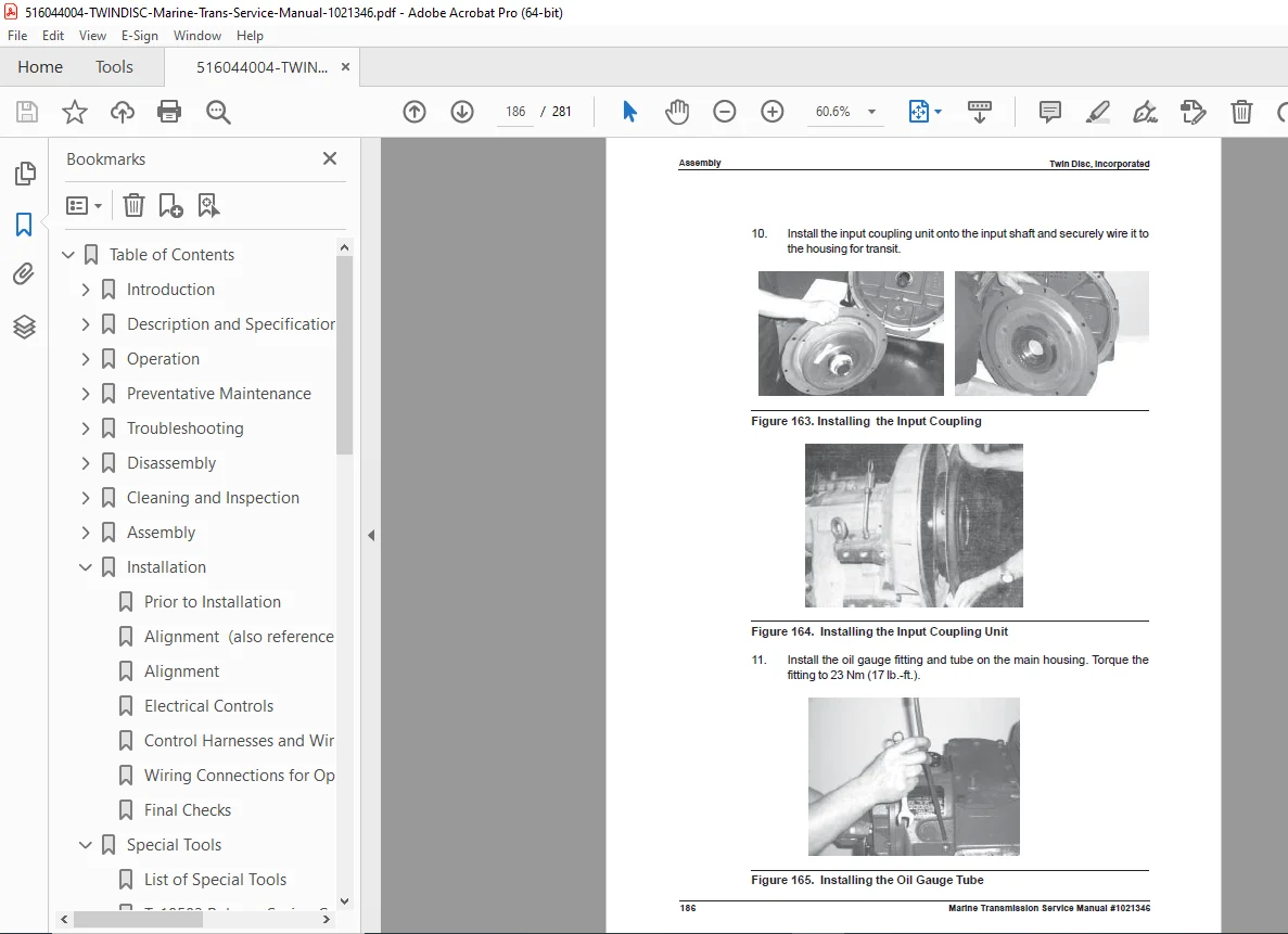
✓ Complete Disassembly/Assembly Procedures – Step-by-step with photos
✓ Torque Specifications – Every fastener torque value
✓ Hydraulic Diagrams – Complete system schematics
✓ Control Valve Service – All valve types (manual, GP, electric)
✓ Special Tool Catalog – 11 specialized tools with part numbers
✓ Alignment Procedures – SAE J-1033 and J-617 standards
✓ Wiring Diagrams – Electronic control modules
✓ Troubleshooting Guides – Symptom-based diagnosis
✓ Endplay Adjustment – Shimming procedures for all shafts
✓ Engineering Drawings – Installation dimensions and specifications
🔍 COMPREHENSIVE COVERAGE INCLUDES
Service Procedures:
- Primary clutch rebuild procedures
- Secondary clutch service
- Output shaft bearing replacement
- Seal replacement (all positions)
- Gear inspection and replacement
- Housing service and repair
Control Valve Service:
- Manual valve disassembly/assembly
- GP valve with electronic interface service
- PX-10225 electric valve rebuild
- 1018084 electric valve service
- Trolling valve adjustment
- Main pressure adjustment
Electronic Controls:
- Profile control module wiring
- E-Troll control module connections
- LED indicator troubleshooting
- Harness routing guidelines
- Connector pin assignments
Installation:
- Engine-to-transmission alignment (SAE standards)
- Coupling alignment procedures
- Mounting specifications
- Fluid filling procedures
- Initial startup checks
🌟 MULTIPLE CONTROL VALVE OPTIONS
Manual Control Valve:
- Mechanical cable or rod shift control
- Simple, reliable operation
- No electrical requirements
GP Control Valve with Electronic Interface:
- Profile module for speed-based shifting
- E-Troll module for trolling applications
- Electronic shift control
- LED diagnostic indicators
- Programmable parameters
PX-10285 Electric Control Valve:
- Electronic shift actuation
- Simplified wiring
- Reliable operation
1018084 Electric Control Valve:
- Alternative electric valve option
- Compatible with various control systems
Trolling Valve (Optional):
- Slow-speed control for fishing
- Adjustable flow restriction
- Independent installation
📱 PERFECT FOR:
- Marine Service Centers – Professional transmission repair
- Boat Dealerships – Sales and service departments
- Charter Boat Operators – Fleet maintenance
- Commercial Fishing Vessels – Offshore fishing boat service
- Yacht Maintenance Crews – High-end vessel service
- Technical Training Schools – Marine mechanics programs
- Twin Disc Distributors – Authorized parts and service
- Independent Marine Mechanics – Self-employed technicians
⚠️ WARRANTY INFORMATION INCLUDED
The manual includes complete warranty documentation:
- 36-Month Warranty – From date of shipment
- 24-Month Service Warranty – Whichever occurs first
- Flat Rate Hour Allowance – 10.0 hours R&R, 17.0 hours rebuild
- Labor Coverage – Authorized labor reimbursement
- Parts Coverage – Defective materials and workmanship
- Warranty Terms – Complete terms and conditions
🔧 SPECIAL TOOLS DOCUMENTATION
Complete special tool catalog with:
- Part numbers for ordering
- Detailed tool illustrations
- Usage instructions
- Application specifications
- Alternative methods (when available)
Essential tools for professional service work on MG-5114SC/SC-HD transmissions!
🌟 INSTANT DOWNLOAD – START SERVICING TODAY!
Don’t let transmission problems keep boats out of service! This genuine Twin Disc factory service manual gives you everything needed to professionally diagnose, rebuild, and install MG-5114SC and MG-5114SC-HD marine transmissions. With 281 pages of detailed procedures, hydraulic diagrams, torque specifications, wiring schematics, and engineering drawings, you’ll have the confidence to tackle any transmission issue from clutch rebuild to complete overhaul. Download now and become your marina’s Twin Disc transmission specialist!
Pricing Rationale:
- Comprehensive 281-page professional service manual
- Covers both standard and heavy-duty models
- Multiple control valve configurations (manual, GP, electric)
- Complete special tool catalog with part numbers
- Extensive engineering drawings (17 sheets)
- Essential for marine transmission service
- Twin Disc factory original documentation
- High-value hydraulic system diagrams
- Professional marine mechanic market
- Includes electronic control module wiring
- Critical alignment procedures (SAE standards)
- Limited availability of genuine Twin Disc service manuals