Trusted Business
Verified & Licensed
Virus Free Files
100% Safe Downloads
Secure Payment
SSL Protected
Instant Delivery
Available Immediately
UNICARRIERS TX30M, TX35M, TX40M Controller Service Manual 997SE-11010 PDF DOWNLOAD
$28.95
UNICARRIERS TX30M, TX35M, TX40M Controller Service Manual 997SE-11010 PDF DOWNLOAD
Service Manual
FC/MC
Controller
TX30M AUB25-00012-09999
TX35M AUB26-00012-09999
TX40M AUB26-50012-59999
997SE-11010
Instant PDF Download
Available immediately
Save to Your Device
Download & keep forever
Antivirus Scanned
100% virus-free
Trusted Worldwide
175,000+ customers
Description
UNICARRIERS TX30M, TX35M, TX40M Controller Service Manual 997SE-11010 PDF DOWNLOAD
FILE DETAILS:
UNICARRIERS TX30M, TX35M, TX40M Controller Service Manual 997SE-11010 PDF DOWNLOAD
Language : English
Pages :311
Downloadable : Yes
File Type : PDF
IMAGES PREVIEW OF THE MANUAL:
TABLE OF CONTENTS:
UNICARRIERS TX30M, TX35M, TX40M Controller Service Manual 997SE-11010 PDF DOWNLOAD
Service Manual
FC/MC
Controller
TX30M AUB25-00012-09999
TX35M AUB26-00012-09999
TX40M AUB26-50012-59999
997SE-11010
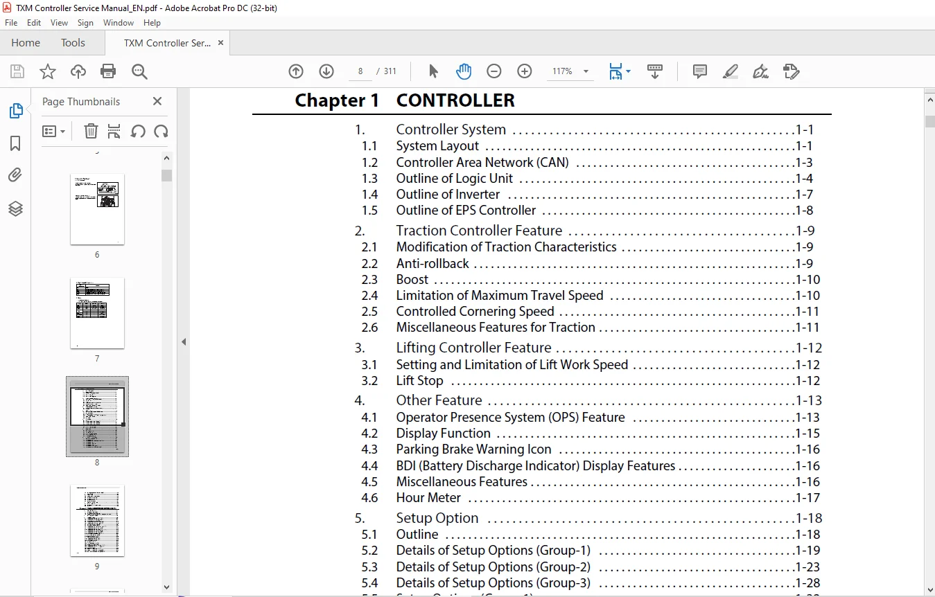
FRONT COVER..........................................................  1
FOREWORD.............................................................  2
	1. Safety........................................................  3
	2. LOCKOUT/TAGOUT................................................  5
	3. How to Use This Manual........................................  6
		3.1 Lift Truck Model.........................................  6
	4. Symbols and Abbreviations.....................................  7
	5. Units.........................................................  7
		Chapter 1 CONTROLLER.........................................  8
		Chapter 2 TROUBLESHOOTING FOR CONTROL CIRCUITS...............  9
		Chapter 3 MOTOR.............................................. 10
		Chapter 4 HOW TO READ CIRCUIT DIAGRAMS....................... 11
		Chapter 5 CIRCUIT DIAGRAM.................................... 11
Chapter 1 CONTROLLER................................................. 12
	1. Controller System............................................. 12
		1.1 System Layout............................................ 12
		1.2 Controller Area Network (CAN)............................ 14
		1.3 Outline of Logic Unit.................................... 15
		1.4 Outline of Inverter...................................... 18
		1.5 Outline of EPS Controller................................ 19
	2. Traction Controller Feature................................... 20
		2.1 Modification of Traction Characteristics................. 20
		2.2 Anti-rollback............................................ 20
		2.3 Boost.................................................... 21
		2.4 Limitation of Maximum Travel Speed....................... 21
		2.5 Controlled Cornering Speed............................... 22
		2.6 Miscellaneous Features for Traction...................... 22
	3. Lifting Controller Feature.................................... 23
		3.1 Setting and Limitation of Lift Work Speed................ 23
		3.2 Lift Stop................................................ 23
	4. Other Feature................................................. 24
		4.1 Operator Presence System (OPS) Feature................... 24
		4.2 Display Function......................................... 26
		4.3 Parking Brake Warning Icon............................... 27
		4.4 BDI (Battery Discharge Indicator) Display Features....... 27
		4.5 Miscellaneous Features................................... 27
		4.6 Hour Meter............................................... 28
	5. Setup Option.................................................. 29
		5.1 Outline.................................................. 29
		5.2 Details of Setup Options (Group-1)....................... 30
		5.3 Details of Setup Options (Group-2)....................... 34
		5.4 Details of Setup Options (Group-3)....................... 39
		5.5 Setup Options (Group 1).................................. 43
		5.6 Setup Options (Group 2).................................. 44
		5.7 Setup Options (Group 3).................................. 46
	6. Diagnostics................................................... 47
		6.1 Outline.................................................. 47
		6.2 Operation Procedure...................................... 47
		6.3 Self-Diagnostics......................................... 49
		6.4 Power Steering Diagnostics............................... 50
		6.5 Run Time Diagnostics..................................... 52
		6.6 Fail-Safe Restriction List............................... 59
	7. Removal and Installation...................................... 61
		7.1 Inverter Discharging Procedure........................... 61
		7.2 Replacing Inverter....................................... 62
		7.3 Replacing DSP (Digital Signal Processor) Card............ 63
		7.4 Replacing Logic Unit..................................... 65
		7.5 Replacing EPS Controller................................. 66
		7.6 Replacing Logic Card..................................... 67
		7.7 Replacing Power Supply Card.............................. 68
		7.8 Replacing FC Armrest (FC Model Only)..................... 69
		7.9 Replacing Output Unit (FC Model Only).................... 70
	8. Basic Check................................................... 71
		8.1 Testing Tools............................................ 71
		8.2 Measurement of Card Voltage.............................. 71
		8.3 Checking Contactor Coil.................................. 77
		8.4 Checking Contactor Tips.................................. 77
		8.5 Checking Inverter........................................ 78
		8.6 Regeneration Check....................................... 78
	9. AC Motor System Basics........................................ 79
		9.1 Feature of AC motor...................................... 79
		9.2 Speed Control of Induction Motors........................ 79
		9.3 Inverter................................................. 80
Chapter 2 TROUBLESHOOTING FOR CONTROL CIRCUITS....................... 81
	1. General Information........................................... 81
		1.1 Before Replacing Devices................................. 81
		1.2 Connection of the Service Tool........................... 81
		1.3 How to Clean Harness Connectors and System Components.... 82
	2. List of Diagnostic Codes...................................... 83
	3. Troubleshooting............................................... 84
		3.1 Traction Motor R.H.,Overheating (E0)..................... 84
		3.2 Traction Motor L.H.,Overheating (E1)..................... 88
		3.3 Pump Motor, Overheating (E2)............................. 92
		3.4 Traction Inverter R.H., Overheating (E5)................. 95
		3.5 Traction Inverter L.H., Overheating (E6)................. 98
		3.6 Pump Inverter, Overheating (E7)..........................101
		3.7 PS Controller, Overheating (E9)..........................104
		3.8 Traction Motor Current Sensor R.H., Fault (14)...........107
		3.9 Traction Motor R.H., Over-current (15)...................109
		3.10 Traction Motor R.H., Stall Timer (16)...................113
		3.11 Traction Motor Current Sensor L.H., Fault (24)..........116
		3.12 Traction Motor L.H., Over-current (25)..................118
		3.13 Traction Motor L.H., Stall Timer (26)...................122
		3.14 Pump Motor Current Sensor Fault (34)....................125
		3.15 Pump Motor Over-current (35)............................127
		3.16 Line Contactor Fault (40)...............................130
		3.17 Steering Contactor Fault (41)...........................133
		3.18 Traction Motor R.H., Open (45)..........................136
		3.19 Traction Motor L.H., Open (46)..........................139
		3.20 Pump Motor Open (47)....................................142
		3.21 PS Motor Open (49)......................................145
		3.22 Tire Angle Sensor Fault (50)............................148
		3.23 Accelerator Sensor Fault (51)...........................151
		3.24 Traction Motor R.H., Pulse Input Fault (52).............154
		3.25 Traction Motor L.H., Pulse Input Fault (53).............157
		3.26 FC Lever Fault (54).....................................160
		3.27 Output Unit Solenoid Fault (55).........................162
		3.28 Output Unit Solenoid Current Leak (56)..................165
		3.29 FNR Lever or Accelerator, Faulty Setting (E)............167
		3.30 Seat Switch, Faulty Setting for Traction ((E))..........170
		3.31 Lift Lever, Faulty Setting (H1).........................173
		3.32 Tilt Lever, Faulty Setting (H2).........................176
		3.33 Attachment 1 Lever, Faulty Setting (H3).................179
		3.34 Attachment 2 Lever, Faulty Setting (H4).................182
		3.35 Seat Switch, Faulty Setting for Hydraulic ((L)).........185
		3.36 FNR Lever Fault (EE)....................................188
		3.37 Display Communication Fault (60)........................190
		3.38 Logic Card Initialize Failure (61)......................193
		3.39 Logics Fault (62).......................................194
		3.40 Traction Inverter R.H., Fault (63)......................195
		3.41 Traction Inverter L.H., Fault (64)......................199
		3.42 Pump Inverter Fault (65)................................203
		3.43 FC Armrest (67).........................................207
		3.44 Output Unit Fault (68)..................................208
		3.45 EPS Controller Fault (71)...............................210
		3.46 Contactor Coil Fault (72)...............................214
		3.47 Hydraulic Lock Solenoid Fault (74)......................216
		3.48 Parking Brake Fault (75)................................218
		3.49 OPS Buzzer Fault (76)...................................220
		3.50 Battery Voltage Too Low (78)............................222
		3.51 Battery Voltage Too High (79)...........................224
		3.52 Battery Consumption Too Much (Lo).......................226
		3.53 Tilt Angle Sensor Fault (80)............................228
		3.54 Load Sensor Fault (81)..................................230
		3.55 Handle Sensor Fault (82)................................232
		3.56 PS Motor Current Sensor Fault (A4)......................234
		3.57 PS Motor Over-current (A5)..............................236
		3.58 PS Handle Brake Fault (A7)..............................238
		3.59 Battery Side Way Exchange Interlock (A8)................240
		3.60 Parking brake warning (A9)..............................242
		3.61 Battery Consumption Much................................244
		3.62 Brake Oil, Low Level....................................246
		3.63 RTC Battery Low.........................................248
Chapter 3 MOTOR......................................................249
	1. Motor Installation Positions..................................249
	2. Specifications................................................250
	3. Structures....................................................251
		3.1 Traction Motor...........................................251
		3.2 Pump Motor...............................................252
		3.3 EPS Motor................................................253
	4. Removing Transfer Assemblies, Traction Motors.................254
	5. Disassembling Traction Motor..................................255
		5.1 Disassembly Sequence.....................................255
	6. Inspecting Traction Motor.....................................256
		6.1 Inspecting Rotor.........................................256
		6.2 Inspecting Motor.........................................256
		6.3 Inspection of Insulation.................................257
	7. Assembling Traction Motor.....................................258
		7.1 Assembly Sequence........................................258
	8. Removing Pump Motor...........................................259
		8.1 Suggestions for Removal..................................259
	9. Disassembling Pump Motor......................................261
		9.1 Disassembly Sequence.....................................261
	10. Inspecting Pump Motor........................................262
		10.1 Inspecting Rotor........................................262
		10.2 Inspecting Motor........................................262
		10.3 Inspection of Insulation................................262
	11. Assembling Pump Motor........................................263
		11.1 Assembly Sequence.......................................263
	12. Tightening of High-power Cable Terminals.....................264
	13. Removing EPS Motor...........................................265
		13.1 Suggestions for Removal.................................265
	14. Disassembling EPS Motor......................................265
	15. Inspecting EPS Motor.........................................266
		15.1 Inspecting Armature.....................................266
		15.2 Inspecting Motor........................................268
		15.3 Inspecting Oil Seal and Permanent Magnet................269
	16. Inspecting EPS Motor.........................................270
		16.1 Brush...................................................270
	17. Troubleshooting..............................................271
Chapter 4 HOW TO READ CIRCUIT DIAGRAMS...............................272
	1. Description of Circuit Diagrams...............................272
		1.1 Schematic Diagram........................................272
		1.2 Connector Diagrams.......................................272
	2. How to Read Circuit Diagrams..................................273
		2.1 Symbols..................................................274
		2.2 Sheet Symbol.............................................277
		2.3 Connecting Lines.........................................278
		2.4 Equipment................................................279
		2.5 Relay Contactor and Coil.................................280
		2.6 Connectors...............................................280
		2.7 Indication of Connecting Line............................281
		2.8 Indication of GND (Earth)................................281
		2.9 Indication of Another Specification......................282
	3. How to Read Connector Diagrams................................283
Chapter 5 CIRCUIT DIAGRAM............................................285
BACK COVER...........................................................311
VIDEO PRVIEW:
https://vimeo.com/859635541?share=copy
DESCRIPTION:
UNICARRIERS TX30M, TX35M, TX40M Controller Service Manual 997SE-11010 PDF DOWNLOAD
FOREWORD
- This service manual is a guide for servicing UniCarriers lift trucks. The long productive life of your lift truck(s) depends on regular and proper servicing, servicing consistent with what you will learn by reading this service manual.
- Read the respective sections of this manual carefully and familiarize yourself with all of the components before attempting to start a test, repair or rebuild the lift truck. The descriptions, illustrations, and specifications contained in this manual are for lift trucks with serial numbers in effect at the time of printing.
- UniCarriers Americas Corporation reserves the right to change specifications or designs without notice and without incurring obligations. For your convenience, the instructions are grouped by systems as an easy reference.
SAFETY:
- The proper and safe lubrication and maintenance for these lift trucks, recommended by UniCarriers Americas Corporation, are outlined in the SERVICE MANUAL. Read and understand the SERVICE MANUAL before performing any lubrication or maintenance on these trucks. Improper performance of lubrication or maintenance procedures is dangerous and could result in injury or death.
- The serviceman or mechanic may be unfamiliar with many of the systems on this lift truck. This makes it important to use caution when performing service work.
- Do not operate these trucks unless you have read and understood the instructions in the SERVICE MANUAL. Improper lift truck operation is dangerous and could result in injury or death.
PLEASE NOTE:
- This is the same manual used by the dealers to diagnose and troubleshoot your vehicle
- You will be directed to the download page as soon as the purchase is completed. The whole payment and downloading process will take anywhere between 2-5 minutes
- Need any other service / repair / parts manual, please feel free to contact [email protected] . We still have 50,000 manuals unlisted
S.S