V4+R Series VRF Heat Recovery Service Manual – 3-Pipe Repair & Diagnostics
Original price was: $75.00.$15.95Current price is: $15.95.
This is the essential V4+R Series VRF Heat Recovery Service Manual, designed for professional HVAC technicians servicing commercial Variable Refrigerant Flow systems. It provides complete diagnostics for 3-pipe heat recovery wiring diagrams, inverter compressor troubleshooting, and simultaneous heating/cooling operation. Covers 8HP–64HP modular outdoor units, VRF error codes, refrigerant circuit logic, and PCB configuration settings for optimal performance.
Description
V4+R Series VRF Heat Recovery Service Manual – 3-Pipe Repair & Diagnostics PDF DOWNLOAD
DESCRIPTION
Master complex commercial HVAC systems with this comprehensive V4+R Series VRF Heat Recovery Service Manual. This factory-grade technical guide is designed for installers, commissioning engineers, and senior HVAC service technicians working with V4+R modular outdoor VRF units.
Unlike conventional heat pump VRF, the V4+R system uses an advanced 3-pipe design to support simultaneous heating and cooling across different zones. This manual provides detailed explanations of the refrigerant flow, mode switching logic, and component interactions that make heat recovery VRF systems unique.
Whether diagnosing inverter failures, interpreting error codes, replacing compressors, or commissioning a large-scale network, this manual provides the exact technical procedures, wiring layouts, and diagnostic tools needed to service the V4+R system with precision.
⚙️ KEY TECHNICAL COVERAGE
System Overview & Specifications
Complete specifications for 8HP, 10HP, 12HP, 14HP, and 16HP modules
Combination charts for building systems up to 64HP
Refrigerant pipe design: maximum lengths, height differences
Outdoor & indoor operating conditions
Refrigerant Circuit Diagrams
Full 3-pipe heat recovery flow diagrams
MS Box (Mode Selection Box) switching logic
Oil return sequence & oil separator mechanics
Subcooling control logic for thermal stability
Heating / Cooling / Heat Recovery mode flow charts
Electrical & Control System
PCB DIP switch settings for capacity, silent mode & addressing
Wiring layouts:
Outdoor Units
Indoor Units
MS Boxes (Heat Recovery Box)
PQE communication wiring standards
EXV (Electronic Expansion Valve) control
Diagnostics & Troubleshooting
Full VRF error code tables (E0–E9, H0–H9, P0–P9)
Troubleshooting flowcharts for:
High-pressure protection
Communication failures
Refrigerant leakage
Sensor failures (T1/T2/T3/T4/T5)
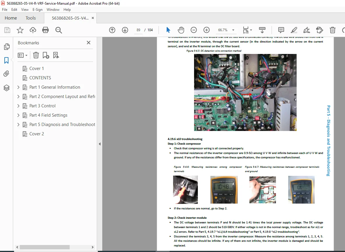
Inverter compressor diagnostics & IPM module testing
Live monitoring and spot-check procedures
Installation & Commissioning
Outdoor unit foundations, service clearances, and spacing
3-pipe refrigerant piping installation (liquid/gas/exhaust lines)
Nitrogen pressure test & vacuum drying
Refrigerant charging procedure
Auto addressing & trial run procedure
📚 TABLE OF CONTENTS
Part 1: General Information
Unit Capacities & Nomenclature
Combination Ratios
System Overview & External Appearance
Part 2: Component Layout & Refrigerant Circuits
Compressor & accumulator layout
Oil separator & heat exchanger locations
Cooling, Heating, and Heat Recovery flow diagrams
Part 3: Control
Central control logic
EXV control sequence
Compressor frequency control
Fan motor control curve
Part 4: Field Settings
Outdoor Unit PCB DIP Settings (ENC1–4, S1–12)
Digital display codes
Spot-check instructions
Part 5: Installation
Outdoor unit foundation requirements
3-Pipe system connection
Electrical wiring requirements
Commissioning & trial operation
Part 6: Troubleshooting
Complete Error Code Tables
Flowcharts for fast diagnosis
Component value checking:
Compressor winding resistance
Sensor resistance (NTC)
Fan motor testing
Inverter & IPM module evaluation
📂 FILE DETAILS
| Field | Details |
|---|---|
| Manual Name | V4+R VRF Series Heat Recovery Service Manual |
| Models Covered | 8HP–64HP V4+R Heat Recovery VRF Outdoor Units |
| System Type | 3-Pipe Heat Recovery VRF |
| Year | Applicable to V4+R generation (multi-year support) |
| PDF Quality | High-definition, searchable PDF |
| Pages | ~104 |