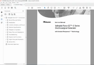
Valleylab Force FX-C Electrosurgical Generator Service Manual PDF
Original price was: $95.00.$30.95Current price is: $30.95.
Official Valleylab Force FX-C Electrosurgical Generator Service Manual — Part No. 1007969 (1 of 2), Effective August 2007. Includes service safety procedures, system theory, REM monitoring, Instant Response™ technology, calibration, leakage current testing, troubleshooting, RS-232 diagnostics, replacement procedures & schematics supplement reference. OEM searchable PDF
Description
Valleylab Force FX-C Electrosurgical Generator Service Manual PDF DOWNLOAD
Description
This OEM Valleylab Force FX-C Electrosurgical Generator Service Manual is the factory technical guide used by biomedical engineers and certified service technicians for professional repair, servicing, diagnostics and calibration of the Force FX-C generator.
According to the Preface and Equipment Identification (page ii–iii), this manual applies to:
Valleylab Force FX-C Electrosurgical Generator
With Instant Response™ Technology
Auto-selecting 100–120V / 220–240V models
Service Manual Part Number 1007969 (1 of 2)
Effective Date: August 2007
The manual consists of two parts:
Service Manual Text (this document)
Schematics Supplement (Part 2 of 2)
⭐ Key Features & Operating Modes (from Section 1 — Introduction)
The generator provides isolated RF output for:
Monopolar Cut — Low / Pure / Blend
Monopolar Coag — Desiccate / Fulgurate / Spray / LCF Fulgurate
Three Bipolar Modes — Precise / Standard / Macro
Simultaneous Coagulation
REM Contact Quality Monitoring
CUSA Ultrasonic Electrosurgery Support
Handswitch or Footswitch Activation
Power Recall Function
RS-232 & Expansion Port Communication
Service safety notes include:
Electric shock hazards
RF burn hazards
ESD handling precautions
Calibration requirements after board replacement
Fuse and heat-sink replacement guidelines
📑 Structured Table of Contents — Major Sections
Section 1 — Introduction
General description & system features
Component list (front panel, rear panel, internal boards)
Service safety precautions
Fire & explosion warnings
Calibration requirements
Cleaning restrictions
Section 2 — Controls, Indicators & Receptacles
Includes detailed diagrams of:
Front panel controls
Bipolar / Cut / Coag mode selectors
Power level displays
Monopolar & Bipolar receptacles
REM Alarm Indicator
CEM module support
Patient return electrode connector
Rear panel
Footswitch connectors
Power entry module & fuse drawer
Activation tone volume control
Option panel — RS-232 / RF Activation / Expansion port
The front-panel layout diagram is clearly shown on page 20.
Section 3 — Technical Specifications
Covers:
Performance characteristics
Duty cycle & output capacity
REM contact quality monitoring thresholds
Leakage current limits
RF output power limits
IEC & EMC classifications
Environmental operating range
Activation & alarm tone specifications
Output waveform descriptions
Power vs. resistance graphs (bipolar / cut / coag)
Includes compliance with:
IEC 60601-1
IEC 60601-2-2
ANSI/AAMI HF18
Section 4 — Principles of Operation
Explains:
Functional block diagrams
Control & feedback microcontrollers
Instant Response™ Algorithm
REM monitoring system
RF output stage
Spark control circuit
Leakage reduction circuitry
IsoBloc circuit
Temperature sensing system
Section 5 — Setup, Tests & Adjustments
Technician-level procedures:
Output verification
REM function testing
Bipolar & monopolar mode testing
High & low frequency leakage testing
Entering calibration mode
Current / voltage / reactance gain adjustments
ECON factor calibration
RS-232 diagnostic commands
Section 6 — Troubleshooting
Includes:
Alarm response tables
Board-level inspection steps
Error code interpretation
T_ON ASIC malfunction correction
Battery RAM failure recovery
Section 7 — Replacement Procedures
Covers step-by-step replacement for:
Battery
Control board
Display board / LED modules
Fans
Footswitch board
Front panel & switches
Fuses (drawer & RF board)
Heat sinks (left/right)
Low-voltage power supply
Power Supply/RF board assembly
Also includes interconnect diagrams & parts lists.
👨⚕️ Who this manual is intended for
✔ Biomedical engineers
✔ Surgical equipment technicians
✔ Hospital maintenance teams
✔ Electrosurgical repair facilities
Contains service-grade diagnostics & calibration not found in user manuals.
📂 File Details
| Field | Details |
|---|---|
| Manual Name | Valleylab Force FX-C Electrosurgical Generator — Service Manual |
| Models Covered | Force FX-C (Instant Response™ Technology) |
| Part Number | 1007969 — Part 1 of 2 |
| Effective Date | August 2007 |
| Manual Type | OEM Service, Calibration & Troubleshooting Manual |
| PDF Quality | Searchable — Bookmarked — OEM Digital Copy |
| Pages | 230 pages |