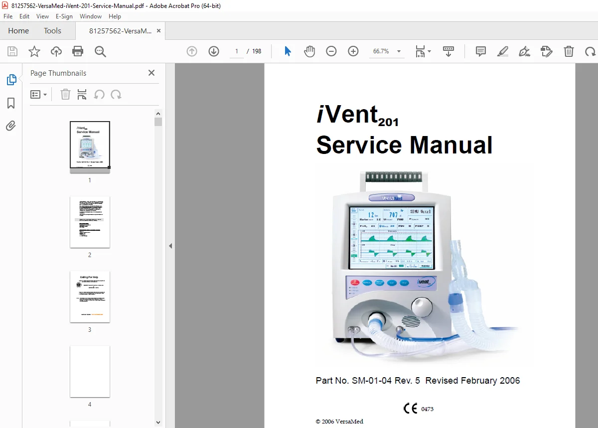
VersaMed iVent201 Ventilator Service, Calibration & Test Manual PDF
Original price was: $95.00.$34.95Current price is: $34.95.
Factory VersaMed iVent201 Service Manual (SM-01-04 Rev.5, Feb 2006) for hardware v1.4. Covers specifications, installation, oxygen supply, patient circuit setup, theory of operation, preventive maintenance, full calibration procedures, ventilator verification tests, disassembly, board-level service, troubleshooting guide, wiring diagrams and technician tool utility
Description
VersaMed iVent201 Ventilator Service, Calibration & Test Manual PDF DOWNLOAD
Description
This official VersaMed iVent201 Ventilator Service Manual is the complete factory guide for maintaining, calibrating, testing and repairing the iVent201 portable critical-care ventilator (hardware version 1.4). It is written for biomedical engineers and authorized service technicians who need detailed step-by-step procedures, specifications and wiring information to keep these units safe and reliable.
1. Introduction & Safety
Section 1 explains the intended use of the iVent201 service manual, technician qualifications and how it complements the Operator’s Manual. It details:
Comprehensive safety information and medical electrical safety standards (IEC 60601 series, ISO 10651, ASTM F1100).
Technician safety rules: disconnecting AC/DC, O₂ supply, and handling high-voltage areas.
ESD protection and proper handling of PC boards.
Critical notes on internal battery replacement, use of genuine parts and reassembly grounding checks.
Full list of front and rear panel labels and IEC symbols for power, oxygen inlet, fuses, alarms, SpO₂, RS-232, Ethernet and power pack.
2. System Specifications & Parameters
Section 2 consolidates all technical data for quick reference:
Supported ventilation modes: A/C Volume & Pressure, SIMV Volume & Pressure, CPAP/PSV, Adaptive Bi-Level.
Performance ranges: respiratory rate, tidal volume (100–2000 ml), inspiratory pressures, Adaptive Flow™, Adaptive Time™, PEEP, FiO₂ control and trigger sensitivities.
Power specs: AC 100–240 V, DC 12–15 V, sealed lead-acid internal battery, recharge and runtime.
Environmental limits (temperature, humidity, altitude, vibration, IP54).
Large monitoring table listing all displayed parameters, set vs measured, across modes, plus non-displayed adjustable settings and user alarms (RR, minute volume, pressure, FiO₂, apnea, leak, low VT).
3. Installation & Setup
Section 3 walks through installing and commissioning the ventilator:
External AC/DC power connections, cable clamp use and power-source icons.
Internal battery charging, charge-level indicator table, and low-battery behavior.
High-pressure and low-pressure oxygen supply options, including DISS inlet, concentrator hookup and FiO₂ monitoring.
Complete patient circuit diagrams: inspiratory/expiratory limbs, exhalation valve, Wye/flow sensor, one-way valve and control lines.
Filter strategy and photos: air inlet filter, low-pressure O₂ adapter, CBRN filter, outlet bacterial filter and HME/filter at the patient wye.
Ventilator controls: rotational encoder, keypad functions (Silence, 100% O₂, Manual Breath, Hold, Clear) and LED indicators for On, Charge and Alarm.
4. Theory of Operation – Pneumatic & Electronics
Section 4 describes how the iVent201 works internally, ideal for deep troubleshooting:
Pneumatic unit: blower/turbine assembly, oxygen blending system, solenoid valves, filters, mufflers, cooling fan and patient circuit flow path (with detailed diagrams).
Blower performance (up to 23,000 RPM, 80–90 cmH₂O) and replacement interval.
Oxygen blending components: O₂ pressure switch, demand valve, proportioning valve, stepper-driven mixer, limit microswitch and galvanic O₂ sensor with life expectations and calibration behavior.
Solenoid valve system for pressure relief and waveform shaping.
Electronic module: computer, main board, zeroing/purge board, switching board and AC/DC power supply. Block descriptions cover sensor interfaces (flow, pressure, O₂, temperature, battery), digital/analog I/O, motor drive, solenoid drive, watchdogs, remote alarm and SpO₂ interface.
5. Maintenance, Preventive Service & Calibration
Section 5 is a complete preventive maintenance program:
Cleaning and routine maintenance tasks in Table 5-1.
PM schedule by run-time: 500-hour, 1500-hour, annual and 15,000-hour service intervals, including filter changes, leak checks, blower replacement and safety verifications.
Long, highly detailed calibration procedure with:
Accessing maintenance and calibration menus.
Zeroing all sensors.
Calibrating pressure sensors, PEEP-RPM, flow, volume and O₂ system.
Saving calibration and required tools/equipment.
6. Ventilator Test Procedures
Section 6 provides structured test suites for post-service validation:
Operational Verification Test (OVT) – quick functionality check after setup or circuit change.
Full Ventilator Verification Test (VVT) – alarm sound checks, pressure, flow and FiO₂ tests, battery and watchdog verification with on-screen examples.
Functional Verification Test (FVT) – O₂ delivery and linearity, 100% O₂ suction mode, high-pressure alarm, apnea and disconnect alarms, sensor-disconnect behavior and detailed acceptance criteria.
These procedures ensure the ventilator meets factory specs after repair or calibration.
7. Service Procedures & Disassembly
Section 7 turns the manual into a true iVent201 ventilator service and calibration manual:
Software upgrade steps, technical log download and option package key update.
Full mechanical teardown:
Enclosure removal and assembly.
Electronic module removal and cover disassembly.
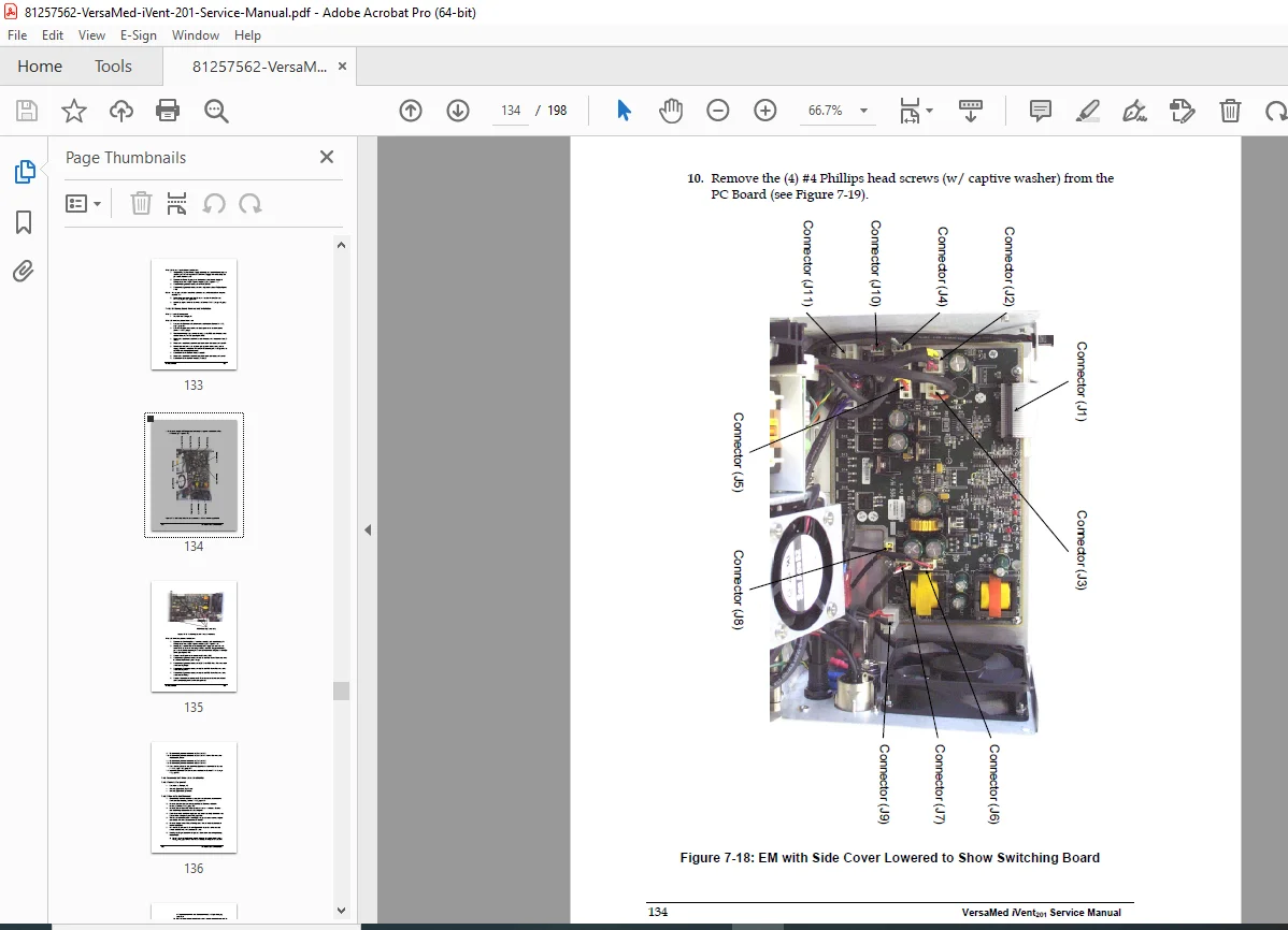
Board-level replacement for Zeroing/Purge PCB, main board, CPU board, power supply, switching board.
Pneumatic unit removal/installation, LCD assembly, interface board and power pack service.
Dedicated O₂ sensor replacement procedure.
Battery gas gauge initialization to correctly reset runtime indicators after battery work.
Exploded views and figure callouts make reassembly and cable routing much easier.
8. Troubleshooting, Diagnostics & Accuracy Issues
Section 8 is a practical troubleshooting guide:
Large table of common symptoms vs probable causes and corrective actions.
Focused repair subsections for power switch, demand valve, O₂ pressure switch and microswitch, flow-sensor leaks and tube issues, blower pressure behavior, exhalation valve control and pressure/flow relationships.
Detailed discussion of inhale/exhale VT accuracy, leakage, flow velocity effects and MAQUET test lung setup, plus “miscellaneous issues” such as black screen, failed calibration, erratic O₂ control or tidal volumes and low pressure during tests.
Appendices – Parts, Reports, Tools & Wiring
Appendix A: Parts and accessories list for field replacement.
Appendix B: Printable service report form for documenting each visit.
Appendix C: Technician Tool Utility Software – installation, communications setup, reading parameters, O₂ raw values, battery LMD, resetting the gas gauge, and setting the machine serial number.
Appendix D: Two-page iVent201 wiring diagram with cable pinouts for in-depth fault finding.
File Details (Quick Reference)
| Field | Details |
|---|---|
| Manual name | iVent201 Service Manual – Part No. SM-01-04 Rev.5 |
| Models covered | VersaMed iVent201 ventilator (hardware version 1.4) |
| Year / Revision | Revised February 2006 |
| Manual PDF quality | OEM factory PDF, text-searchable, clear diagrams, full ToC, figures & tables |
| Number of pages | 198 pages of service, test & wiring info |
When you’re servicing or buying a used VersaMed iVent201, this manual is the difference between guessing and using factory-approved procedures. It gives you the calibration menus, acceptance limits and wiring details that generic guides simply don’t include—helping you reduce downtime and avoid costly repeat failures.