Villa Sistemi Medicali Apollo 0051 Service Manual PDF
Original price was: $65.00.$25.95Current price is: $25.95.
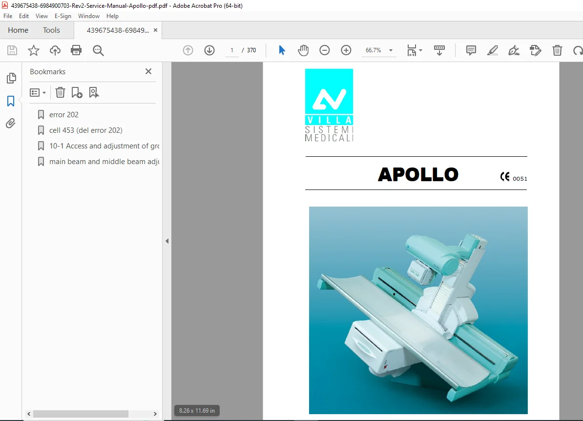
Official Villa Sistemi Medicali Apollo 0051 radiography and fluoroscopy (R&F) service manual (Document 6984900703, Rev.2, April 2005, Author: moltdani). This comprehensive 370-page technical manual covers ID plates, safety aspects, radioprotection, technical specifications, pre-installation requirements, installation procedures, tube support arm assembly, image intensifier installation, collimator setup, and complete service information for qualified biomedical engineers servicing medical diagnostic X-ray imaging systems.
Description
Villa Sistemi Medicali Apollo 0051 Service Manual X-Ray System 6984900703C – PDF DOWNLOAD
DESCRIPTION
This is the official Villa Sistemi Medicali Apollo 0051 Service Manual (Document Number 6984900703, Revision 2, Version April 27, 2005, Author: moltdani). This comprehensive 370-page technical manual is intended for qualified biomedical equipment engineers and provides complete installation, maintenance, troubleshooting, and repair procedures for the Apollo radiography and fluoroscopy (R&F) system used in hospitals, medical imaging centers, and diagnostic facilities worldwide for general diagnostic radiology examinations.
Product Overview
Villa Sistemi Medicali Apollo 0051 R&F System:
The Apollo 0051 represents Villa Sistemi Medicali’s advanced radiography and fluoroscopy system designed for comprehensive diagnostic imaging. This sophisticated medical equipment combines precision X-ray tube positioning, image intensifier technology, motorized table movements, digital imaging capabilities, and comprehensive patient positioning to deliver high-quality diagnostic radiographic and fluoroscopic examinations for diverse clinical applications.
Key Applications:
- General radiography
- Fluoroscopy examinations
- Gastrointestinal (GI) studies
- Urological examinations
- Orthopedic imaging
- Vascular studies
- Barium contrast studies
- Interventional procedures
- General diagnostic radiology
- Multi-purpose imaging
System Configuration
Apollo 0051 System Components:
- Base with beam and column
- Tube support arm
- Spot film device
- Tilting table with tabletop
- Left and right tabletop support arms
- Image intensifier (various sizes)
- X-ray tube and collimator assembly
- Control desk with CPU
- Generator system
- Motorized positioning systems
Image Intensifier Options:
- 9-12″ fixed Image Intensifier
- 16″ fixed Image Intensifier (Toshiba model)
- 9″ with lift Image Intensifier
- 12″ with lift Image Intensifier
- 16″ with lift Image Intensifier
Key Technical Systems
Mechanical System:
- Motorized table tilt
- Tube support arm movements
- Image intensifier positioning
- Tabletop movements
- Compressor cone adjustment
- Patient positioning mechanisms
X-Ray Generation:
- High voltage generator
- X-ray tube
- Collimator with beam limitation
- Radiation monitoring
- Exposure control
- kV and mA selection
Image Reception:
- Image intensifier (I.I.)
- TV camera
- Spot film device
- Digital image capture
- Image processing
Control System:
- CPU control board
- Inverter control
- Motor control circuits
- Position sensors
- Safety interlocks
- User interface
Electrical System:
- Main power distribution
- Control circuits
- Motor drives
- Safety circuits
- Emergency stop systems
Comprehensive Manual Contents
DOCUMENT INFORMATION:
- Document Number: 6984900703
- Title: Apollo 0051 Service Manual
- Revision: 2
- Version Date: April 27, 2005
- Author: moltdani
- Manufacturer: Villa Sistemi Medicali
- Pages: 370 pages
- Format: A4 (595 x 842 pts)
- Creator: ADOBEPS4.DRV Version 4.24
- Producer: Acrobat Distiller 4.0 for Windows
- Creation Date: April 29, 2005
- Modified Date: March 27, 2018
- PDF Version: 1.3
- File Size: 12.0 MB
REVISION HISTORY
Revision 0 (January 14, 2005):
- Document approval
- Initial release
Revision 1 (March 29, 2005):
- Pages affected: 6-2, 6-14, 6-44, 17-5, 22-129 to 22-145
- A14 Control desk CPU PCB layout and wiring diagram update
- Parameter 74 update in Inverter setting
- Description of basement grubs regulation
- Reference: RDM 6040, RDM 6078, RDM 6092
Revision 2 (April 27, 2005):
- Pages affected: 4-6, 4-11, 6-44, 7-1, 8-1, 8-3, 9-2, 11-10, 11-13, 11-16, 11-25, 11-26, 13-6, 13-10, 22-9 to 22-45, 22-49, 22-69 to 22-77, 22-81 to 22-95
- Change of min and max height of compressor cone with respect to tabletop
- Release of SW Version 1.03 (correcting minor bugs and introducing improvements)
- Wiring diagrams and drawings update
- Reference: RDM 6008, RDM 6103, RDM 6104
COMPLETE TABLE OF CONTENTS
CHAPTER 1: INTRODUCTION (Pages 1-1 to 1-2)
1.1 Symbols Used in This Manual:
- Safety symbols
- Warning indicators
- Caution symbols
- Information markers
1.2 How to Contact Villa Sistemi Medicali Technical Service:
- Service contact information
- Technical support
- Emergency contacts
CHAPTER 2: SAFETY ASPECTS (Pages 2-1 to 2-8)
2.1 Warnings:
- General safety precautions
- Equipment hazards
- Operational safety
- Service personnel requirements
2.2 Radioprotection Warnings:
- Radiation safety
- Exposure limits
- Lead shielding requirements
- Monitoring requirements
- Personnel protection
2.3 Environmental Risks and Disposal:
- Environmental considerations
- Waste disposal regulations
- Hazardous materials
- Recycling requirements
2.4 Used Symbols:
- Symbols on equipment
- Warning labels
- Identification markings
CHAPTER 3: DESCRIPTION (Pages 3-1 to 3-3)
3.1 ID Plates:
- Serial number location
- Model identification
- Regulatory markings
- Manufacturer information
3.2 Description:
- System overview
- Component identification
- Configuration options
- System capabilities
CHAPTER 4: TECHNICAL DATA (Pages 4-1 to 4-11)
4.1 Technical Features:
- System specifications
- Performance parameters
- Electrical ratings
- Mechanical specifications
4.2 Formats Division Table in Centimeters:
- Image field sizes (metric)
- Format specifications
4.3 Formats Division Table in Inches:
- Image field sizes (imperial)
- Format specifications
4.4 Standards and Regulations:
- IEC compliance
- Safety standards
- Medical device regulations
- EMC requirements
4.5 Dimensions:
- System dimensions
- Space requirements
- Component measurements
- Installation footprint
CHAPTER 5: PRE-INSTALLATION (Pages 5-1 to 5-7)
5.1 Space Requirements:
- Room dimensions
- Clearance requirements
- Access space
- Equipment layout
5.2 Electrical Provisions:
- Power supply requirements
- Circuit specifications
- Grounding requirements
- Emergency power
5.3 Adaptation to the Mains Voltage:
- Voltage configuration
- Regional specifications
- Transformer settings
5.4 Environmental Conditions:
- Temperature range
- Humidity specifications
- Ventilation requirements
- Environmental controls
CHAPTER 6: INSTALLATION (Pages 6-1 to 6-44+)
6.1 Base Positioning with Beam and Column:
- Foundation requirements
- Base mounting procedures
- Beam installation
- Column assembly
- Alignment procedures
6.2 Assembly of the Tube Support Arm:
- Support arm installation
- Mounting procedures
- Cable routing
- Movement verification
6.3 Spot Film Device Assembly:
- Spot film device installation
- Cassette holder mounting
- Alignment procedures
6.4 Left- and Right-Hand Tabletop Support Arm Assembly:
- Support arm installation
- Both sides assembly
- Adjustment procedures
6.5 Machine Cable Connection:
- Power cable installation
- Control cable routing
- Interconnection wiring
- Grounding connections
- Cable identification
6.6 Image Intensifier Installation:
6.6.1 9-12″ Fixed Image Intensifier (I.I.) Installation:
- Mounting procedures
- Alignment
- Cable connections
6.6.2 16″ Fixed Image Intensifier (I.I.) Installation (Toshiba Model):
- Toshiba-specific procedures
- Mounting requirements
- Integration steps
6.6.3 Image Intensifier (I.I.) with Lift Installation:
6.6.3.1 9″ with Lift I.I. Installation:
- Lift mechanism installation
- I.I. mounting
- Movement calibration
6.6.3.2 12″ I.I. with Lift Installation:
- Installation procedures
- Lift system setup
6.6.3.3 16″ I.I. with Lift Installation:
- Large format installation
- Lift mechanism setup
6.7 Installation of the Tube – Collimator Group:
- X-ray tube installation
- Collimator mounting
- Alignment procedures
- Cable routing
- Cooling system connection
REMAINING CHAPTERS (Chapters 7-22+)
Based on typical medical imaging system service manual structure:
Chapter 7: Electrical System
- Wiring diagrams
- Power distribution
- Control circuits
Chapter 8: Control System
- CPU board
- Inverter settings
- Parameter configuration
Chapter 9: Calibration and Adjustments
- System calibration
- Movement adjustments
- Image quality optimization
Chapter 10-13: Service Procedures
- Preventive maintenance
- Component replacement
- Troubleshooting
Chapters 14-22: Technical Documentation
- Detailed wiring diagrams (pages 22-9 to 22-145)
- PCB layouts
- Component specifications
- Parts lists
Who Needs This Manual?
This Villa Sistemi Medicali Apollo service manual is essential for:
- Biomedical equipment engineers
- Medical imaging service technicians
- X-ray equipment specialists
- Hospital clinical engineering departments
- Villa Sistemi Medicali authorized service centers
- Radiology equipment maintenance teams
Prerequisites:
✓ Biomedical equipment technician certification
✓ X-ray equipment service experience
✓ Understanding of radiography and fluoroscopy systems
✓ Electrical and mechanical troubleshooting skills
✓ Radiation safety training
✓ High voltage equipment experience
✓ Proper tools and test equipment
✓ Safety training for medical imaging equipment
FILE DETAILS
| Detail | Specification |
|---|---|
| Document Number | 6984900703 |
| Manual Title | Apollo 0051 Service Manual |
| Revision | 2 |
| Version Date | April 27, 2005 |
| Author | moltdani |
| Manufacturer | Villa Sistemi Medicali |
| Product | Apollo 0051 Radiography & Fluoroscopy System |
| System Type | R&F (Radiography and Fluoroscopy) |
| Software Version | 1.03 (as of Rev. 2) |
| Pages | 370 pages |
| PDF Quality | Professional technical manual with detailed diagrams |
| File Size | 12.0 MB |
| Page Size | A4 (595 x 842 pts) |
| Language | English |
| Creator | ADOBEPS4.DRV Version 4.24 |
| Producer | Acrobat Distiller 4.0 for Windows |
| Creation Date | April 29, 2005 |
| Modified Date | March 27, 2018 |
| PDF Version | 1.3 |