Trusted Business
Verified & Licensed
Virus Free Files
100% Safe Downloads
Secure Payment
SSL Protected
Instant Delivery
Available Immediately
Volkswagen Golf IV Bora Repair Manual_1999 – PDF DOWNLOAD
$46.95
Volkswagen Golf IV Bora Repair Manual_1999 – PDF DOWNLOAD
Instant PDF Download
Available immediately
Save to Your Device
Download & keep forever
Antivirus Scanned
100% virus-free
Trusted Worldwide
175,000+ customers
Description
Volkswagen Golf IV Bora Repair Manual_1999 – PDF DOWNLOAD
FILE DETAILS:
Volkswagen Golf IV Bora Repair Manual_1999 – PDF DOWNLOAD
Language : English
Pages : 10594
Downloadable : Yes
File Type : PDF
IMAGES PREVIEW OF THE MANUAL:
TABLE OF CONTENTS:
Volkswagen Golf IV Bora Repair Manual_1999 – PDF DOWNLOAD
00053148620 Wheels and Tyres Guide Archive 1
44 – Wheels, tyres, vehicle geometry 11
1 General notes on wheels and tyres (passenger cars) 11
2 Legislative and technical conditions for converting wheel and tyre combinations 13
2 1 Legislative conditions for converting wheel and tyre combinations 13
2 2 Technical conditions for converting wheel and tyre combinations 13
2 3 Additional wheel housing extensions (flaps) 14
2 4 “Series 80” tyres 14
2 5 Vehicles with Plus running gear 14
3 Documents and codes/designations 16
3 1 New vehicle registration documents since 01 10 2005 16
3 2 COC document (EEC Certificate of Conformity) 17
3 3 Official type designations 17
3 4 EU general type approval number, sales type and sales or trade designation 18
4 Useful information regarding tyres 20
4 1 Identification markings on the tyre sidewall 20
4 2 Explanation of tyre markings 21
4 3 Speed ratings for tyres 22
4 4 Undulations 23
4 5 Tyre storage 24
4 6 Tyre ageing 24
4 7 Winter tyres 25
4 8 Winter tyres with speed symbol “V” 26
4 9 Extra Load (XL) V winter tyres 27
4 10 Maximum speeds for V and Extra Load (XL) winter tyres 27
4 11 Reinforced and Extra Load (XL) tyres 28
4 12 Snow chains 28
5 Tyre wear/ mileage for passenger car tyres 30
5 1 General 30
5 2 Requirements to be met by tyres 30
5 3 Wear behaviour of high-speed tyres 31
5 4 Factors influencing the service life of a tyre 31
5 5 Driving style 31
5 6 Tyre maintenance 32
5 7 Evenly worn tyres 33
5 8 Measuring tread depth 34
5 9 One-sided wear 34
5 10 Outer shoulder wear 37
5 11 Wear in middle of tyre 37
5 12 Diagonal washout 39
6 Tyre noise 40
6 1 General notes on tyre noise 40
6 2 Saw-tooth wear 40
6 3 Flat spots (from locking wheels) 41
7 Rough running caused by wheels/tyres 43
7 1 Causes of rough running 43
7 2 Balancing wheels 43
7 3 Conducting a road test before balancing wheels 43
7 4 Balancing wheels on stationary wheel balancing machine 44
7 5 Vibration control system -VAS 6230- 46
7 6 Finish balancer 46
7 7 Radial and lateral runout of wheels and tyres 47
7 8 Checking radial and lateral runout on wheels and tyres with tyre gauge -V A G 1435- 47
7 9 Checking radial and lateral runout on wheel rim 48
7 10 Matching 49
7 11 Flat spots caused by storage or handling 50
8 Vehicle pulls to one side 52
8 1 General 52
8 2 Conicity 52
8 3 Remedies when vehicle pulls to one side 53
8 4 Strategic rotation of wheels for non-directional tyres 54
8 5 Strategic rotation of wheels having unidirectional tyres 55
9 Tyre damage 57
9 1 General information 57
9 2 Construction of a radial belted tyre 57
9 3 Impact damage 58
9 4 Cuts 59
9 5 Damage caused by foreign bodies 59
9 6 Loss of air from tyre 60
9 7 Tyre pressure 60
9 8 Tyre damage due to insufficient tyre pressure 61
9 9 Rising tyre temperature caused by insufficient inflation pressure 62
9 10 Tyre damage due to fitting error (fitting damage) 63
10 Tyres with run-flat properties 65
10 1 General 65
10 2 Design and identification 66
10 3 Retrofitting/requirements when using run-flat tyres 66
10 4 Repairs 67
11 Rolling resistance optimised tyres 68
12 Facts about disc-type wheels (passenger cars) 69
12 1 Design of disc-type wheel 69
12 2 Data on wheel rims 69
12 3 Wheel rims – pitch circle diameter 70
12 4 Split rim composite wheels 70
12 5 Alloy wheels with exchangeable trim elements 70
12 6 Alloy wheels with exchangeable trim elements (Zaragoza) 71
12 6 1 Tools 71
12 6 2 Materials 72
12 6 3 Installing trim element 72
12 6 4 Removing trim element 74
12 7 Hub cover for alloy wheels with open threaded connections 75
12 8 Care and maintenance of alloy wheel rims 75
12 9 Restoring alloy wheels 76
12 10 The valve 77
13 Fitting and removing wheels 78
13 1 Rotating wheels 78
13 2 Instructions for changing or fitting wheels 78
13 3 Revised wheel bolts for Sharan from model year 2001 80
13 4 Notes on use of temporary spare wheels 80
14 Lupo 3L, Lupo FSI, Lupo GTI from model year 1999 82
14 1 Lupo 3L, type 6E model year 1999 to model year 2006 82
14 2 Wheel allocation for Lupo 3L, type 6E model year 1999 to model year 2006 83
14 2 1 4 J x 14 83
14 2 2 41/2 J x 14 83
14 2 3 5 J x 14 84
14 3 Lupo FSI, type 6E model year 2001 to model year 2006 84
14 4 Wheel allocation for Lupo FSI, type 6E model year 2001 to model year 2006 85
14 4 1 5 J x 14 85
14 4 2 6 J x 14 86
14 5 Lupo GTI, type 6ES model year 2001 to model year 2006 87
14 6 Wheel allocation for Lupo GTI, type 6ES model year 2001 to model year 2006 88
14 6 1 6 J x 14 88
14 6 2 61/2 J x 15 89
15 Lupo model year 1999 to model year 2005 90
15 1 Lupo, type 6X model year 1999 to model year 2005 90
15 2 Wheel allocation for Lupo, type 6X model year 1999 to model year 2005 92
15 2 1 41/2 J x 13 92
15 2 2 51/2 J x 13 93
15 2 3 6 J x 14 94
15 2 4 6 J x 15 96
16 Fox from model year 2005 98
16 1 Fox, type 5Z model year 2005 to model year 2012 98
16 2 Wheel allocation for Fox, type 5Z model year 2005 to model year 2012 99
16 2 1 5 J x 14 100
16 2 2 6 J x 14 100
16 2 3 6 J x 15 102
17 Polo model year 1995 to model year 2001 105
17 1 Polo, type 6N up to and including 07 95 105
17 2 Wheel allocation for Polo, type 6N up to and including 07 95 106
17 2 1 41/2 J x 13 106
17 2 2 51/2 J x 13 107
17 3 Polo, type 6N from 08 95 up to and including model year 1996 108
17 4 Polo, type 6N from model year 1997 to model year 1999 109
17 5 Wheel allocation for Polo, type 6N from 08 95 to model year 1999 110
17 5 1 41/2 J x 13 111
17 5 2 51/2 J x 13 111
17 5 3 6 J x 14 112
17 5 4 6 J x 15 113
17 6 Polo, type 6N from model year 2000 to model year 2001 115
17 7 Wheel allocation for Polo, type 6N from model year 2000 to model year 2001 116
17 7 1 41/2 J x 13 117
17 7 2 51/2 J x 13 117
17 7 3 6 J x 14 118
17 7 4 6 J x 15 119
18 Polo Classic model year 1996 to model year 2002 122
18 1 Polo Classic, type 6KV model year 1996 to model year 2002 122
18 2 Wheel allocation for Polo Classic, type 6KV model year 1996 to model year 2002 124
18 2 1 51/2 J x 13 124
18 2 2 6 J x 14 125
18 2 3 6 J x 15 126
19 Polo Variant model year 1998 to model year 2002 128
19 1 Polo Variant type 6KV model year 1998 to model year 2002 128
19 2 Wheel allocation for Polo Variant type 6KV model year 1998 to model year 2002 130
19 2 1 51/2 J x 13 130
19 2 2 6 J x 14 131
19 2 3 6 J x 15 132
20 Polo from model year 2002 134
20 1 Polo, type 9N model year 2002 to model year 2008 134
20 2 Polo, type 9N model year 2009 137
20 3 Wheel allocation for Polo, type 9N model year 2002 to model year 2009 141
20 3 1 5 J x 13 141
20 3 2 5 J x 14 142
20 3 3 6 J x 14 142
20 3 4 6 J x 15 144
20 3 5 61/2 J x 16 offset 38 145
20 3 6 61/2 J x 16 offset 43 145
20 3 7 71/2 J x 17 offset 38 148
21 Polo Fun model year 2004 to model year 2005 149
21 1 Polo Fun, type 9N model year 2004 to model year 2005 149
21 2 Wheel allocation for Polo Fun, type 9N model year 2004 to model year 2005 150
21 2 1 6 J x 15 150
21 2 2 71/2 J x 17 150
22 CrossPolo from model year 2006 152
22 1 CrossPolo, type 9N model year 2006 to model year 2009 152
22 2 Wheel allocation for CrossPolo, type 9N model year 2006 to model year 2009 153
22 2 1 6 J x 15 153
22 2 2 71/2 J x 17 153
23 Polo BlueMotion from model year 2007 155
23 1 Polo BlueMotion, type 9N model year 2007 to model year 2009 155
23 2 Wheel allocation for Polo BlueMotion, type 9N model year 2007 to model year 2009 156
23 2 1 5 J x 14 156
24 Polo GTI from model year 2006 158
24 1 Polo GTI, type 9N model year 2006 to model year 2009 158
24 2 Wheel allocation for Polo GTI, type 9N model year 2006 to model year 2009 159
24 2 1 6 J x 15 159
24 2 2 61/2 J x 16 offset 38 160
24 2 3 61/2 J x 16 offset 43 160
24 2 4 7 J x 17 offset 38 162
24 2 5 71/2 J x 17 offset 38 163
25 Polo GTI Cup Edition from model year 2007 164
25 1 Polo GTI Cup Edition, type 9N model year 2007 to model year 2009 164
25 2 Wheel allocation for Polo GTI Cup Edition, type 9N model year 2007 to model year 2009 165
25 2 1 61/2 J x 16 offset 42 165
25 2 2 61/2 J x 16 offset 43 166
25 2 3 7 J x 17 offset 38 167
25 2 4 71/2 J x 17 offset 38 168
26 Polo saloon/sedan model year 2004 to model year 2005 169
26 1 Polo saloon/sedan, type 9N model year 2004 to model year 2005 169
26 2 Wheel allocation for Polo saloon/sedan, type 9N model year 2004 to model year 2005 171
26 2 1 5 J x 14 171
26 2 2 6 J x 14 171
26 2 3 6 J x 15 173
26 2 4 61/2 J x 16 174
27 Golf model year 1992 to model year 1998 176
27 1 Golf type 1HX0, Golf Syncro 1HX1, Golf type 1H 176
27 2 Wheel allocation for Golf type 1HX0, Golf Syncro 1HX1, Golf type 1H 180
27 2 1 51/2 J x 13 180
27 2 2 6 J x 14 181
27 2 3 6 J x 15 183
27 2 4 61/2 J x 15 186
27 2 5 7 J x 16 189
28 Golf model year 1998 to model year 2004, Golf R32, Golf Anniversary GTI 190
28 1 Golf, Golf 4Motion, type 1J model year 1998 to model year 2004 190
28 2 Wheel allocation for Golf, Golf 4Motion, type 1J model year 1998 to model year 2004 193
28 2 1 6 J x 14 193
28 2 2 6 J x 15 194
28 2 3 51/2 J x 16 197
28 2 4 61/2 J x 16 198
28 2 5 7 J x 17 202
28 2 6 71/2 J x 17 204
28 3 Conditions for fitting 17″ wheels and tyres to Golf model year 1998 to model year 2004 205
28 4 Golf R32, type 1J model year 2003 to model year 2005 206
28 5 Wheel allocation for Golf R32, type 1J model year 2003 to model year 2005 206
28 5 1 51/2 J x 17 207
28 5 2 71/2 J x 17 207
28 5 3 71/2 J x 18 207
28 6 Golf Anniversary GTI, type 1J model year 2002 208
28 7 Wheel allocation for Golf Anniversary GTI, type 1J model year 2002 208
28 7 1 51/2 J x 16 209
28 7 2 61/2 J x 16 209
28 7 3 7 J x 17 211
28 7 4 71/2 J x 18 212
28 8 Conditions for fitting 17″ and 18″ wheels and tyres of Golf Anniversary GTI 213
29 Golf model year 2004 to model year 2009 214
29 1 Golf, Golf 4Motion, type 1K model year 2004 to model year 2006 214
29 2 Golf, Golf 4Motion, type 1K model year 2007 to model year 2009 217
29 3 Wheel allocation for Golf, Golf 4Motion, type 1K model year 2004 to model year 2009 221
29 3 1 6 J x 15 221
29 3 2 61/2 J x 15 222
29 3 3 6 J x 16 223
29 3 4 61/2 J x 16 223
29 3 5 6 J x 17 227
29 3 6 7 J x 17 228
29 3 7 71/2 J x 17 230
29 3 8 71/2 J x 18 231
30 Golf BlueMotion model year 2008 to model year 2009 234
30 1 Golf BlueMotion, type 1K model year 2008 to model year 2009 234
30 2 Wheel allocation for Golf BlueMotion, type 1K model year 2008 to model year 2009 235
30 2 1 6 J x 15 235
30 2 2 61/2 J x 15 236
30 2 3 61/2 J x 16 237
31 Golf GTI model year 2005 to model year 2009 242
31 1 Golf GTI, type 1K model year 2005 to model year 2008 242
31 2 Golf GTI, type 1K model year 2009 243
31 3 Wheel allocation for Golf GTI, type 1K model year 2005 to model year 2009 245
31 3 1 6 J x 16 245
31 3 2 61/2 J x 16 245
31 3 3 6 J x 17 249
31 3 4 7 J x 17 250
31 3 5 71/2 J x 17 252
31 3 6 71/2 J x 18 253
32 Pirelli Golf model year 2008 to model year 2009 256
32 1 Pirelli Golf, type 1K model year 2008 to model year 2009 256
32 2 Wheel allocation for Pirelli Golf, type 1K model year 2008 to model year 2009 257
32 2 1 6 J x 16 257
32 2 2 61/2 J x 16 258
32 2 3 6 J x 17 262
32 2 4 7 J x 17 262
32 2 5 71/2 J x 17 265
32 2 6 71/2 J x 18 266
33 Golf R32 model year 2006 to model year 2009 269
33 1 Golf R32, type 1K model year 2006 to model year 2009 269
33 2 Wheel allocation for Golf R32, type 1K model year 2006 to model year 2009 270
33 2 1 6 J x 17 270
33 2 2 7 J x 17 271
33 2 3 71/2 J x 18 273
34 CrossGolf from model year 2007 276
34 1 CrossGolf, type 1KP model year 2007 to model year 2009 276
34 2 Wheel allocation for CrossGolf, type 1KP model year 2007 to model year 2009 279
34 2 1 6 J x 15 279
34 2 2 61/2 J x 15 280
34 2 3 6 J x 16 281
34 2 4 61/2 J x 16 282
34 2 5 6 J x 17 286
34 2 6 7 J x 17 offset 47 286
34 2 7 7 J x 17 offset 54 287
34 2 8 71/2 J x 17 289
35 Golf Plus from model year 2005 290
35 1 Golf Plus, type 1KP model year 2005 to model year 2006 290
35 2 Golf Plus, type 1KP model year 2007 to model year 2009 292
35 3 Wheel allocation for Golf Plus, type 1KP model year 2005 to model year 2009 295
35 3 1 6 J x 15 296
35 3 2 61/2 J x 15 296
35 3 3 6 J x 16 297
35 3 4 61/2 J x 16 298
35 3 5 6 J x 17 302
35 3 6 7 J x 17 303
35 3 7 71/2 J x 18 305
36 Golf Plus BlueMotion from model year 2008 308
36 1 Golf Plus BlueMotion, type 1KP model year 2008 to model year 2009 308
36 2 Wheel allocation for Golf Plus BlueMotion, type 1KP model year 2008 to model year 2009 309
36 2 1 6 J x 15 309
36 2 2 61/2 J x 15 310
36 2 3 61/2 J x 16 311
37 Golf Variant model year 1994 to model year 1998 316
37 1 Golf Variant type 1HX0, Golf Variant Syncro type 1HX1, Golf Variant type 1H 316
37 2 Wheel allocation for Golf Variant type 1HX0, Golf Variant Syncro type 1HX1, Golf Variant type 1H 319
37 2 1 51/2 J x 13 320
37 2 2 6 J x 14 320
37 2 3 6 J x 15 323
37 2 4 61/2 J x 15 326
38 Golf Variant model year 1999 to model year 2006, Bora Variant model year 1999 to model year 2005 327
38 1 Golf Variant, Golf Variant 4Motion, Bora Variant, Bora Variant 4Motion, type 1J 327
38 2 Wheel allocation for Golf Variant, Golf Variant 4Motion, Bora Variant, Bora Variant 4Motion, type 1J 330
38 2 1 6 J x 15 330
38 2 2 51/2 J x 16 333
38 2 3 61/2 J x 16 334
38 2 4 7 J x 17 338
38 2 5 71/2 J x 17 340
38 3 Conditions for fitting 17″ wheels and tyres 341
39 Golf Variant model year 2007 to model year 2010 342
39 1 Golf Variant, Golf Variant 4Motion; type 1KM model year 2007 to model year 2008 342
39 2 Golf Variant, Golf Variant 4Motion; type 1KM model year 2009 to model year 2010 345
39 3 Wheel allocation for Golf Variant, Golf Variant 4Motion; type 1KM model year 2007 to model year 2010 348
39 3 1 6 J x 15 348
39 3 2 61/2 J x 15 349
39 3 3 6 J x 16 350
39 3 4 61/2 J x 16 351
39 3 5 7 J x 17 355
39 3 6 71/2 J x 18 357
40 Golf Variant BlueMotion model year 2008 to model year 2010 360
40 1 Golf Variant BlueMotion, type 1KM model year 2008 to model year 2010 360
40 2 Wheel allocation for Golf Variant BlueMotion, type 1KM model year 2008 to model year 2010 361
40 2 1 6 J x 15 361
40 2 2 61/2 J x 15 362
40 2 3 61/2 J x 16 363
41 Jetta Model Year 2006 to Model Year 2011 368
41 1 Jetta, type 1KM model year 2006 368
41 2 Jetta, type 1KM model year 2007 to model year 2008 370
41 3 Jetta, type 1KM model year 2009 to model year 2011 373
41 4 Wheel allocation for Jetta, type 1KM model year 2006 to model year 2011 380
41 4 1 6 J x 15 380
41 4 2 61/2 J x 15 381
41 4 3 6 J x 16 382
41 4 4 61/2 J x 16 383
41 4 5 7 J x 17 388
41 4 6 71/2 J x 17 391
41 4 7 71/2 J x 18 392
42 Jetta BlueMotion from Model year 2008 397
42 1 Jetta BlueMotion, type 1KM model year 2008 to model year 2011 397
42 2 Wheel allocation for Jetta BlueMotion, type 1KM model year 2008 to model year 2011 398
42 2 1 6 J x 15 398
42 2 2 61/2 J x 15 399
42 2 3 6 J x 16 400
42 2 4 61/2 J x 16 401
43 Golf cabriolet model year 1994 to model year 1997 407
43 1 Golf cabriolet type 1EX0 model year 1994 to model year 1997 407
43 2 Wheel allocation for Golf cabriolet, type 1EX0 from model year 1994 to model year 1997 408
43 2 1 6 J x 14 409
43 2 2 6 J x 15 410
43 2 3 61/2 J x 16 410
44 Golf cabriolet model year 1998 to model year 2002 412
44 1 Golf cabriolet; type 1E from model year 1998 to model year 2002 412
44 2 Wheel allocation for Golf cabriolet; type 1E from model year 1998 to model year 2002 413
44 2 1 6 J x 14 413
44 2 2 6 J x 15 415
44 2 3 61/2 J x 16 417
45 Vento from model year 1992 to model year 1998 418
45 1 Vento; type 1HX0, 1H 418
45 2 Wheel allocation for Vento; type 1HX0, 1H 420
45 2 1 51/2 J x 13 420
45 2 2 6 J x 14 421
45 2 3 6 J x 15 423
45 2 4 61/2 J x 15 425
46 Bora model year 1999 to model year 2005 429
46 1 Bora, Bora 4Motion, type 1J model year 1999 to model year 2005 429
46 2 Wheel allocation for Bora, Bora 4Motion, type 1J model year 1999 to model year 2005 432
46 2 1 6 J x 15 432
46 2 2 51/2 J x 16 435
46 2 3 61/2 J x 16 435
46 2 4 7 J x 17 440
46 2 5 71/2 J x 17 442
46 3 Conditions for fitting 17″ wheels and tyres 443
47 New Beetle from model year 1999 444
47 1 New Beetle, type 9C model year 1999 to model year 2010 444
47 2 Wheel allocation for New Beetle, type 9C model year 1999 to model year 2010 447
47 2 1 6 J x 15 447
47 2 2 51/2 J x 16 449
47 2 3 61/2 J x 16 450
47 2 4 7 J x 17 455
47 2 5 71/2 J x 17 458
47 3 Conditions for fitting 17″ wheels and tyres 458
48 New Beetle Cabriolet from model year 2003 460
48 1 New Beetle Cabriolet, type 1Y model year 2003 to model year 2010 460
48 2 Wheel allocation for New Beetle Cabriolet, type 1Y model year 2003 to model year 2010 462
48 2 1 6 J x 15 462
48 2 2 51/2 J x 16 464
48 2 3 61/2 J x 16 465
48 2 4 7 J x 17 470
48 2 5 71/2 J x 17 473
48 3 Conditions for fitting 17″ wheels and tyres 473
49 New Beetle RSi 475
49 1 New Beetle RSi, type 9CR from model year 2001 475
49 2 Wheel allocation for New Beetle RSi, type 9CR from model year 2001 476
49 2 1 7 J x 16 476
49 2 2 9 x 18 476
50 Passat model year 1994 to model year 1997 478
50 1 Passat, type 35l model year 1994 to model year 1997 478
50 2 Wheel allocation for Passat, type 35l model year 1994 to model year 1997 480
50 2 1 6 J x 14 480
50 2 2 6 J x 15 482
51 Passat model year 1997 to model year 2005 486
51 1 Passat, Passat Variant, type 3B model year 1997 to model year 2000 486
51 2 Passat, Passat Variant, type 3B model year 1997 to model year 2000 488
51 2 1 6 J x 15 488
51 2 2 7 J x 15 489
51 2 3 7 J x 16 490
51 3 Passat, Passat Variant, type 3BG model year 2001 to model year 2005 491
51 4 Wheel allocation for Passat, Passat Variant, type 3BG model year 2001 to model year 2005 492
51 4 1 6 J x 15 493
51 4 2 7 J x 15 494
51 4 3 6 J x 16 494
51 4 4 7 J x 16 495
51 4 5 7 J x 17 497
51 5 Passat W8 4Motion, type 3BS model year 2002 to model year 2005 498
51 6 Wheel allocation for Passat W8 4Motion, type 3BS model year 2002 to model year 2005 499
51 6 1 7 J x 16 499
51 6 2 6 J x 17 500
51 6 3 71/2 J x 17 500
51 7 Passat Protect, type 3BL model year 2002 to model year 2005 501
51 8 Wheel allocation for Passat Protect, type 3BL model year 2002 to model year 2005 502
51 8 1 6 J x 16 502
51 8 2 7 J x 16 502
52 Passat saloon from model year 2006 504
52 1 Passat saloon, type 3C model year 2006 504
52 2 Passat saloon, type 3C model year 2007 to model year 2008 507
52 3 Passat saloon, type 3C model year 2009 515
52 4 Passat saloon, type 3C model year 2010 to model year 2011 522
52 5 Wheel allocation for Passat saloon, type 3C model year 2006 to model year 2011 526
52 5 1 61/2 J x 16 526
52 5 2 7 J x 16 527
52 5 3 6 J x 17 529
52 5 4 71/2 J x 17 529
52 5 5 8 J x 18 532
53 Passat saloon BlueMotion from model year 2008 535
53 1 Passat saloon BlueMotion, type 3C model year 2008 to model year 2009 535
53 2 Passat saloon BlueMotion, type 3C model year 2010 to model year 2011 537
53 3 Wheel allocation for Passat saloon BlueMotion, type 3C model year 2008 to model year 2011 538
53 3 1 61/2 J x 16 538
53 3 2 7 J x 16 539
53 3 3 6 J x 17 541
53 3 4 71/2 J x 17 541
53 3 5 8 J x 18 544
54 Passat Variant from model year 2006 547
54 1 Passat Variant, type 3C model year 2006 547
54 2 Passat Variant, type 3C model year 2007 to model year 2008 551
54 3 Passat Variant, type 3C model year 2009 561
54 4 Passat Variant, type 3C model year 2010 to model year 2011 569
54 5 Wheel allocation for Passat Variant, type 3C model year 2006 to model year 2011 573
54 5 1 61/2 J x 16 573
54 5 2 7 J x 16 574
54 5 3 6 J x 17 576
54 5 4 71/2 J x 17 576
54 5 5 8 J x 18 579
55 Passat Variant BlueMotion from model year 2008 582
55 1 Passat Variant BlueMotion, type 3C model year 2008 to model year 2009 582
55 2 Passat Variant BlueMotion, type 3C model year 2010 to model year 2011 584
55 3 Wheel allocation for Passat Variant BlueMotion, type 3C model year 2008 to model year 2011 585
55 3 1 61/2 J x 16 585
55 3 2 7 J x 16 586
55 3 3 6 J x 17 588
55 3 4 71/2 J x 17 588
55 3 5 8 J x 18 591
56 Passat R36 from model year 2008 594
56 1 Passat R36, type 3C model year 2008 to model year 2009 594
56 2 Passat R36, type 3C model year 2010 to model year 2011 596
56 3 Wheel allocation for Passat R36, type 3C model year 2008 to model year 2011 597
56 3 1 6 J x 17 597
56 3 2 71/2 J x 17 597
56 3 3 8 J x 18 600
56 3 4 8 J x 19 601
57 Sharan from model year 1996 603
57 1 Sharan, Sharan Syncro, type 7M model year 1996 to model year 2000 603
57 2 Wheel allocation for Sharan, Sharan Syncro Type 7M model year 1996 to model year 2000 606
57 2 1 6 J x 15 606
57 2 2 7 J x 15 607
57 2 3 7 J x 16 608
57 3 Sharan, Sharan 4Motion, type 7M model year 2001 608
57 4 Wheel allocation for Sharan, Sharan 4Motion, type 7M model year 2001 611
57 4 1 6 J x 15 611
57 4 2 7 J x 15 611
57 4 3 6 J x 16 612
57 4 4 7 J x 16 613
57 5 Sharan, Sharan 4Motion, type 7M model year 2002 to model year 2010 615
57 6 Wheel allocation for Sharan, Sharan 4Motion, type 7M model year 2002 to model year 2010 616
57 6 1 6 J x 16 617
57 6 2 7 J x 16 617
57 6 3 7 J x 17 619
58 Sharan BlueMotion from model year 2009 621
58 1 Sharan BlueMotion, type 7M model year 2009 to model year 2010 621
58 2 Wheel allocation for Sharan BlueMotion, type 7M model year 2009 to model year 2010 622
58 2 1 6 J x 16 622
59 Touareg from model year 2003 624
59 1 Touareg, type 7L, model year 2003 to model year 2010 624
59 2 Wheel allocation for Touareg, type 7L model year 2003 to model year 2010 628
59 2 1 7 J x 16 628
59 2 2 71/2 J x 17 629
59 2 3 8 J x 18 630
59 2 4 9 J x 19 632
59 2 5 9 J x 20 634
59 2 6 91/2 J x 20 636
60 Touareg R50 from model year 2008 637
60 1 Touareg R50, type 7L model year 2008 to model year 2010 637
60 2 Wheel allocation for Touareg R50, type 7L model year 2008 to model year 2010 638
60 2 1 9 J x 19 638
60 2 2 9 J x 20 640
60 2 3 91/2 J x 20 641
60 2 4 10 J x 21 641
61 Breakdown set for VW Vehicles 643
62 Temporary spare tyres and wheels for VW vehicles 644
63 Recommended summer tyres 646
63 1 Summer tyres for Lupo 3L model year 1999 to model year 2005 646
63 2 Summer tyres for Lupo FSI model year 1999 to model year 2005 646
63 3 Summer tyres for Lupo GTI model year 1999 to model year 2005 646
63 4 Summer tyres for Lupo model year 1999 to model year 2005 646
63 5 Summer tyres for Fox from model year 2005 647
63 6 Summer tyres for Polo model year 1995 to model year 2001 647
63 7 Summer tyres for Polo saloon/sedan model year 2004 to model year 2005 648
63 8 Summer tyres for Polo Classic model year 1996 to model year 2002 648
63 9 Summer tyres for Polo Variant model year 1998 to model year 2002 649
63 10 Summer tyres for Polo from model year 2002 649
63 11 Summer tyres for Polo Fun model year 2004 to model year 2005 650
63 12 Summer tyres for CrossPolo from model year 2006 650
63 13 Summer tyres for Polo BlueMotion from model year 2007 651
63 14 Summer tyres for Polo GTI from model year 2007 651
63 15 Summer tyres for Polo GTI Cup Edition from model year 2007 651
63 16 Summer tyres for Golf, Vento model year 1992 to model year 1998 651
63 17 Summer tyres for Golf Variant model year 1994 to model year 1998 652
63 18 Summer tyres for Golf cabriolet model year 1994 to model year 1997 653
63 19 Summer tyres for Golf, Golf 4Motion model year 1998 to model year 2004 653
63 20 Summer tyres for Golf model year 2004 to model year 2009 654
63 21 Summer tyres for Golf BlueMotion model year 2008 to model year 2009 656
63 22 Summer tyres for Golf GTI model year 2005 to model year 2009 656
63 23 Summer tyres for Pirelli Golf model year 2008 to model year 2009 656
63 24 Summer tyres for Golf R32 model year 2006 to model year 2009 657
63 25 Summer tyres for CrossGolf from model year 2007 657
63 26 Summer tyres for Golf Plus from model year 2005 658
63 27 Summer tyres for Golf Plus BlueMotion from model year 2008 659
63 28 Summer tyres for Bora, Bora 4Motion model year 1999 to model year 2005 659
63 29 Summer tyres for Golf Variant, Golf Variant 4Motion model year 1999 to model year 2006, Bora Variant, Bora Variant 4Motion model year 1999 to model year 2005 660
63 30 Summer tyres for Golf R32 661
63 31 Summer tyres for Golf Anniversary GTI 662
63 32 Summer tyres for Golf Variant model year 2007 to model year 2010 662
63 33 Summer tyres for Golf Variant BlueMotion from model year 2008 663
63 34 Summer tyres for Jetta Model Year 2006 to Model Year 2011 663
63 35 Summer tyres for Jetta BlueMotion Model Year 2008 to Model Year 2011 665
63 36 Summer tyres for Golf cabriolet model year 1998 to model year 2002 666
63 37 Summer tyres for New Beetle from model year 1999 667
63 38 Summer tyres for New Beetle Cabriolet from model year 2003 668
63 39 Summer tyres for New Beetle RSi 668
63 40 Summer tyres for Passat model year 1994 to model year 1997 669
63 41 Summer tyres for Passat model year 1997 to model year 2005 669
63 42 Summer tyres for Passat W8 670
63 43 Summer tyres for Passat Protect 670
63 44 Summer tyres for Passat saloon from model year 2006 670
63 45 Summer tyres for Passat saloon BlueMotion from model year 2008 671
63 46 Summer tyres for Passat Variant from model year 2006 672
63 47 Summer tyres for Passat Variant BlueMotion from model year 2008 673
63 48 Summer tyres for Passat R36 from model year 2008 674
63 49 Summer tyres for Sharan from model year 1996 675
63 50 Summer tyres for Sharan BlueMotion from model year 2009 675
63 51 Summer tyres for Touareg model year 2008 to model year 2010 676
63 52 Summer tyres for Touareg R50 model year 2008 to model year 2010 676
64 Recommended all-season tyres 677
64 1 All-season tyres Lupo model year 1999 to model year 2005 677
64 2 All-season tyres Polo model year 1995 to model year 2001 677
64 3 All-season tyres for Polo from model year 2002 677
64 4 All-season tyres Polo saloon/sedan model year 2004 to model year 2005 678
64 5 All-season tyres Golf, Vento model year 1992 to model year 1998 678
64 6 All-season tyres Golf Variant model year 1994 to model year 1998 678
64 7 All-season tyres Golf cabriolet model year 1994 to model year 1997 678
64 8 All-season tyres Golf, Golf 4Motion model year 1998 to model year 2004 678
64 9 All-season tyres for Golf model year 2004 to model year 2009 679
64 10 All-season tyres for CrossGolf from model year 2007 679
64 11 All-season tyres for Golf Plus from model year 2005 680
64 12 All-season tyres Bora, Bora 4Motion model year 1999 to model year 2005 680
64 13 All-season tyres Golf Variant, Golf Variant 4Motion model year 1999 to model year 2006, Bora Variant, Bora Variant 4Motion model year 1999 to model year 2005 681
64 14 All-season tyres Golf Variant model year 2007 to model year 2010 681
64 15 All-season tyres Jetta Model Year 2006 to Model Year 2011 681
64 16 All-season tyres Golf cabriolet model year 1998 to model year 2002 682
64 17 All-season tyres for New Beetle from model year 1999 682
64 18 All-season tyres for New Beetle Cabriolet from model year 2003 683
64 19 All-season tyres Passat model year 1997 to model year 2005 683
64 20 All-season tyres for Passat W8 683
64 21 All-season tyres for Passat saloon from model year 2006 684
64 22 All-season tyres for Passat saloon BlueMotion from model year 2008 684
64 23 All-season tyres for Passat Variant from model year 2006 684
64 24 All-season tyres for Passat Variant BlueMotion from model year 2008 684
64 25 All-season tyres for Passat R36 from model year 2008 685
64 26 All-season tyres for Touareg model year 2003 to model year 2010 685
65 Recommended winter tyres 686
65 1 Winter tyres Lupo 3L model year 1999 to model year 2005 686
65 2 Winter tyres Lupo FSI model year 1999 to model year 2005 686
65 3 Winter tyres Lupo GTI model year 1999 to model year 2005 686
65 4 Winter tyres Lupo model year 1999 to model year 2005 687
65 5 Winter tyres for Fox from model year 2005 687
65 6 Winter tyres Polo model year 1995 to model year 2001 687
65 7 Winter tyres for Polo from model year 2002 688
65 8 Winter tyres for Polo Fun model year 2004 to model year 2006 688
65 9 Winter tyres for CrossPolo from model year 2006 688
65 10 Winter tyres for Polo BlueMotion from model year 2007 688
65 11 Winter tyres for Polo GTI from model year 2007 689
65 12 Winter tyres for Polo GTI Cup Edition from model year 2007 689
65 13 Winter tyres Polo saloon/sedan model year 2004 to model year 2005 689
65 14 Winter tyres Polo Classic model year 1996 to model year 2002 689
65 15 Winter tyres Polo Variant model year 1998 to model year 2002 690
65 16 Winter tyres Golf, Vento model year 1992 to model year 1998 690
65 17 Winter tyres Golf Variant model year 1994 to model year 1998 691
65 18 Winter tyres Golf cabriolet model year 1994 to model year 1997 691
65 19 Winter tyres Golf, Golf 4Motion model year 1998 to model year 2004 691
65 20 Winter tyres for Golf model year 2004 to model year 2009 692
65 21 Winter tyres for Golf BlueMotion model year 2004 to model year 2009 693
65 22 Winter tyres for Golf GTI model year 2005 to model year 2009 693
65 23 Winter tyres for Pirelli Golf model year 2008 to model year 2009 693
65 24 Winter tyres for Golf R32 model year 2006 to model year 2009 694
65 25 Winter tyres for CrossGolf from model year 2007 694
65 26 Winter tyres for Golf Plus from model year 2005 694
65 27 Winter tyres for Golf Plus BlueMotion from model year 2008 695
65 28 Winter tyres Bora, Bora 4Motion model year 1999 to model year 2005 695
65 29 Winter tyres Golf Variant, Golf Variant 4Motion model year 1999 to model year 2006, Bora Variant, Bora Variant 4Motion model year 1999 to model year 2005 696
65 30 Winter tyres for Golf 32 696
65 31 Winter tyres for Golf Anniversary GTI 696
65 32 Winter tyres Golf Variant model year 2007 to model year 2010 697
65 33 Winter tyres for Golf Variant BlueMotion model year 2008 to model year 2010 697
65 34 Winter tyres Jetta Model Year 2006 to Model Year 2011 698
65 35 Winter tyres Jetta BlueMotion Model Year 2008 to Model Year 2011 698
65 36 Winter tyres Golf cabriolet model year 1998 to model year 2002 698
65 37 Winter tyres for New Beetle from model year 1999 699
65 38 Winter tyres for New Beetle Cabriolet from model year 2003 699
65 39 Winter tyres for New Beetle RSi 700
65 40 Winter tyres Passat model year 1994 to model year 1997 700
65 41 Winter tyres Passat model year 1997 to model year 2005 700
65 42 Winter tyres for Passat W8 701
65 43 Winter tyres for Passat Protect 701
65 44 Winter tyres for Passat saloon from model year 2006 701
65 45 Winter tyres for Passat saloon BlueMotion from model year 2008 702
65 46 Winter tyres for Passat Variant from model year 2006 702
65 47 Winter tyres for Passat Variant BlueMotion from model year 2008 703
65 48 Winter tyres for Passat R36 from model year 2008 703
65 49 Winter tyres for Sharan from model year 1996 704
65 50 Winter tyres for Sharan BlueMotion from model year 2009 704
65 51 Winter tyres for Touareg model year 2003 to model year 2010 704
65 52 Winter tyres for Touareg R50 model year 2008 to model year 2010 704
00053201020 Body repairs Volkswagen cars Golf Vento Cabriolet Passat 94 Golf 98 706
Contents 708
1 Safety instructions 710
1 1 Removing components 710
1 2 Battery, welding work 710
1 3 Electronic control units 710
1 3 1 Procedure for handling electronic control units after accident repairs 710
1 4 Paint, glass, upholstery, trim 711
1 5 Fuel tank or fuel pipes 711
1 6 Air conditioner 711
1 6 1 Remedy: 711
1 7 Airbag system 712
1 8 Checking seat belts 712
1 8 1 Checking belt webbing 713
1 8 2 Checking inertia reel (locking effect) 714
1 8 3 Belt lock – visual check 714
1 8 4 Belt lock – functional check 714
1 8 5 Checking belt guides and lock tongues 715
1 8 6 Checking securing parts and anchorage points 715
1 9 Safety regulations for belt tensioners 715
1 10 Body repairs on vehicles fitted with belt tensioners 716
1 10 1 The following list of vehicles are equipped with: 717
1 11 Cutting, straightening and/or panel beating work on vehicles fitted with airbag 717
1 12 Removing front seats with side airbag 717
2 Fundamental instructions 719
2 1 Diagnosis on accident vehicles 719
2 2 Conditions in which body and/or parts are passed for painting 719
2 3 Straightening 719
2 4 Parting cuts 719
2 5 Replacement body sub-parts and part sections 720
2 6 Original joint 720
2 7 Galvanized body parts 720
2 8 Removing remaining material 720
2 9 New parts 721
2 10 Replacement parts 721
3 Symbols 722
3 1 Symbols for welding operations 722
3 2 Symbols for working procedures 722
3 2 1 Grind 722
3 2 2 Offset 723
3 2 3 Punch 723
3 2 4 Drill 723
3 2 5 Grind 724
3 2 6 Cavity preservation 724
3 2 7 Bond 724
3 2 8 Seal 724
4 Body repair tools 725
4 1 Flanging tool V A G1317 725
4 2 Hole punch V A G1329 725
4 3 Basic equipment V A G1366/3 725
4 4 Underseal spray gun V A G1379 725
4 5 Hot air blower V A G1416 726
4 6 Mechanical door tensioner V A G1438 726
4 7 Body equipment trolley V A G1439 726
4 8 Pneumatic sabre saw V A G1523A 726
4 9 Pneumatic hammer V A G1577 727
4 10 Fold crimping tool V A G1585 727
4 11 Local exhaust ventilation unit V A G1586 727
4 12 Spot weld breaker V A G1731 727
4 13 Pneumatic cartridge gun V A G1761/1 728
4 14 Pneumatic punch and offset tool VAS1996 728
4 15 Pneumatic glue gun V A G2005 728
4 16 Door hinge alignment tool 728
4 17 Hose set 5023 729
4 18 Angle grinder VAS5174 729
4 19 Angle grinder VAS5175 729
4 20 Wire brush VAS5182 729
5 Body bonded joints 730
5 1 Transporter 1991 ‰ 730
5 1 1 Separating procedure: 730
5 1 2 Bonding procedure: 730
5 2 Types of bonded joints 730
5 2 1 Joints bonded for strength 730
5 2 2 Spot welded bonded joints 730
5 3 Repair solutions for part section replacement 731
5 3 1 RP spot welding and bonding 731
5 3 2 SG welding and bonding (when spot welding is not possible) 731
5 3 3 Extraction of welding fumes 731
5 3 4 Preparation 731
5 3 5 Supplementary work 731
6 Anti-corrosion measures 732
6 1 Anti-corrosion protection 732
7 Disposal instructions 733
7 1 Disposal 733
7 2 Releasing gas from strut 733
7 3 Airbag 734
7 3 1 Disposal 734
8 Contact corrosion protection 735
8 1 Joining aluminium/magnesium and steel 735
9 Steel sheet repairs 736
9 1 Strengthened steel body panels 736
9 2 Galvanized body parts 737
9 2 1 Preparation 737
9 2 2 Parting cuts 737
9 2 3 Joint techniques 737
9 3 Welding work on galvanized body panels 737
9 3 1 SG inert gas welding of galvanized panels 737
9 3 2 RP welding of galvanized panels 738
9 3 3 Welding transformer 738
9 3 4 Welding clamp 738
9 4 Unbuttoning test 738
10 Aluminium repairs 739
10 1 Paint 739
10 2 Surface preparation 739
10 3 Removing dents 740
10 4 Temperature regulation when heating 740
11 Synthetic material repair procedures 741
11 1 Materials 741
11 2 Repairing dents 743
11 3 Repairing scratches 745
11 4 Repairing cracks (up to 100 mm in length) 746
11 5 Repairing hole (up to 30 mm diameter) 747
11 6 Synthetic material repair (glass fibre materials) 748
11 7 Repair procedures 749
11 7 1 Repairing rupture/hole 749
11 7 2 Repairing damaged surfaces 750
12 Glass repair 751
12 1 Repairing windscreen 751
12 1 1 Prerequisites 751
12 1 2 Special tools, workshop equipment, testers, measuring instruments and auxiliary items requ 752
12 1 3 Description of repair 753
BOR53201020 Body Repairs 756
00 – Technical data 762
1 Vehicle identification data 762
1 1 Vehicle identification number 762
1 2 Identification plate 762
1 3 Vehicle data plate 762
2 Body foam insulation 763
3 Galvanized body parts 764
4 Strengthened steel body panels 765
5 Laser welding 766
6 Body panel gaps/shut lines 767
6 1 Body – front (Golf) 767
6 2 Body – rear (Golf) 769
6 3 Body – front (Bora) 771
6 4 Body – rear (Bora) 773
6 5 Body – rear (estate) 775
7 Body dimensions 777
7 1 Body – front 777
7 2 Body – centre 781
7 3 Body – rear (Golf) 788
7 4 Body – rear (Bora) 791
7 5 Body – rear (estate) 794
7 6 Floor group – front 797
7 7 Floor group – centre 798
7 8 Floor group – rear 799
8 Alignment jig 800
8 1 Overview, Golf 800
8 2 Overview, Bora, Bora estate, Golf estate 811
8 3 Overview, Golf 4MOTION 814
8 4 Overview, Bora 4MOTION, Bora estate 4MOTION, Golf estate 4MOTION 819
8 5 Portal gauge (2-door) 824
8 6 Portal gauge (4-door) 825
50 – Body – front 826
1 Renewing engine bracket 826
1 1 Right engine console 826
1 1 1 Cutting locations 826
1 1 2 Replacement part 827
2 Renewing intermediate piece 828
2 1 Removing 828
2 1 1 Cutting locations 828
2 1 2 Replacement part 829
3 Renewing wing connecting plate 830
3 1 Removing 830
3 1 1 Cutting locations 830
3 1 2 Replacement part 831
4 Renewing upper wheel housing longitudinal member 832
4 1 Removing 832
4 1 1 Cutting locations 832
4 1 2 Replacement part 833
5 Renewing front wheel housing 834
5 1 Removing 834
5 1 1 Cutting locations 834
5 1 2 Replacement part 835
6 Renewing front wheel housing – partial renewal 836
6 1 Removing 836
6 1 1 Cutting locations 836
6 1 2 Replacement part 837
7 Renewing front longitudinal member 838
7 1 Removing 838
7 1 1 Cutting locations 838
7 1 2 Replacement parts 839
8 Renewing front longitudinal member – partial renewal 840
8 1 Removing 840
8 1 1 Cutting locations 840
8 1 2 Replacement parts 841
9 Renewing front section of longitudinal member 842
9 1 Removing 843
9 1 1 Cutting locations 843
9 1 2 Replacement parts 844
51 – Body – centre 846
1 Renewing roof (Golf) 846
1 1 Removing 847
1 1 1 Cutting locations 847
1 1 2 Replacement parts 848
2 Renewing roof (Bora) 850
2 1 Removing 851
2 1 1 Cutting locations 851
2 1 2 Replacement parts 851
3 Renewing roof (estate) 853
3 1 Tools 853
3 1 1 Special tools, workshop equipment, testers, measuring instruments and auxiliary items required 853
3 1 2 Cutting locations 855
3 1 3 Replacement parts 857
3 2 Dimensions for roof railing 859
4 Renewing front roof cross member 860
4 1 Removing 860
4 1 1 Cutting locations 860
4 1 2 Replacement part 861
5 Renewing roof reinforcement 862
5 1 Removing 862
5 1 1 Cutting locations 862
5 1 2 Replacement part 863
6 Renewing rear roof cross member (Golf) 864
6 1 Removing 864
6 1 1 Cutting locations 864
6 1 2 Replacement part 865
7 Renewing rear roof cross member (Bora) 866
7 1 Removing 866
7 1 1 Cutting locations 866
7 1 2 Replacement part 867
8 Renewing rear roof cross member (estate) 868
8 1 Removing 868
8 1 1 Cutting locations 868
8 1 2 Replacement part 869
8 1 3 Welding in 869
9 Renewing A-pillar 870
9 1 Removing 870
9 1 1 Cutting locations 871
9 1 2 Replacement part 872
10 Renewing inner A-pillar 874
10 1 Removing 874
10 1 1 Cutting locations 875
10 1 2 Replacement parts 876
10 1 3 Foam insulation 876
11 Renewing B-pillar (4-door), renewing B-pillar (Bora) 877
11 1 Removing 878
11 1 1 Cutting locations 878
11 1 2 Replacement part 879
12 Renewing inner B-pillar (2-door) 880
12 1 Removing 880
12 1 1 Cutting locations 880
12 1 2 Replacement part 881
12 1 3 Preparing new part 881
13 Renewing inner B-pillar (Golf 4-door), renewing inner B-pillar (Bora) 883
13 1 Removing 883
13 1 1 Cutting locations 883
13 1 2 Replacement parts 885
13 1 3 Preparing new parts 885
14 Renewing outer side member (2-door) 887
14 1 Removing 887
14 1 1 Cutting locations 887
14 1 2 Replacement part 888
15 Renewing outer side member (Golf 4-door), renewing outer side member (Bora) 890
15 1 Removing 891
15 1 1 Cutting locations 891
15 1 2 Replacement parts 892
16 Renewing side member reinforcement 893
16 1 Includes: Web plate part section 893
16 1 1 Cutting locations 893
16 1 2 Replacement parts 894
17 Renewing floor panel – partial renewal 896
17 1 Removing 896
17 1 1 Cutting locations 896
17 1 2 Part section repair 897
17 1 3 Replacement parts 897
53 – Body – rear 899
1 Renewing rear cross panel (Golf) 899
1 1 Removing 899
1 1 1 Cutting locations 899
1 1 2 Replacement part 900
2 Renewing outer rear cross panel (estate) 901
2 1 Tools 901
2 1 1 Special tools, workshop equipment, testers, measuring instruments and auxiliary items required 901
2 2 Removing 902
2 2 1 Cutting locations 902
2 2 2 Replacement parts 902
3 Renewing complete rear cross panel (estate) 905
3 1 Tools 905
3 1 1 Required special tools, workshop equipment, test and measuring devices and auxiliary items 905
3 2 Removing 905
3 2 2 Cutting locations 906
3 3 Welding in lock carrier 907
3 3 1 Replacement parts 907
3 4 Welding in inner side panel 907
3 4 1 Replacement parts 907
3 5 Welding in lower D-pillar reinforcing 908
3 5 1 Replacement part 908
3 6 D-pillar reinforcing 909
3 6 1 Replacement part 909
3 7 Welding in inner D-pillar reinforcing 910
3 7 1 Replacement part 910
3 8 Welding in tail light cluster mounting 911
3 8 1 Replacement part 911
3 9 Welding cross member to inner rear cross panel 911
3 9 1 Replacement part 911
4 Renewing rear cross panel (4MOTION) 912
4 1 Removing 912
4 1 1 Cutting locations 912
4 1 2 Replacement part 913
5 Renewing complete rear cross panel (4MOTION) 914
5 1 Removing 914
5 1 1 Cutting locations 914
5 1 4 Replacement parts 915
6 Renewing centre piece of rear cross panel (Bora) 918
6 1 Removing 918
6 1 1 Cutting locations 918
6 1 2 Replacement parts 919
6 1 3 Fitting 919
7 Renewing rear roof cross panel (Bora) 921
7 1 Removing 921
7 1 1 Cutting locations 921
7 1 2 Replacement parts 922
8 Renewing tail light mounting (Golf) 923
8 1 Removing 923
8 1 1 Cutting locations 923
8 1 4 Replacement part 924
9 Renewing cross member carrier (Golf) 926
9 1 Removing 926
9 1 1 Cutting locations 926
9 1 2 Replacement part 927
10 Renewing cross member carrier (Bora) 928
10 1 Removing 928
10 1 1 Cutting locations 928
10 1 2 Replacement part 929
11 Renewing towing eye (4MOTION) 930
11 1 Removing 930
11 1 1 Cutting locations 930
11 1 2 Replacement part 931
12 Renewing C-pillar reinforcement (estate) 933
12 1 Removing 933
12 1 1 Cutting locations 933
12 1 2 Replacement part 934
12 1 3 Welding in 934
13 Renewing cover plate (Bora) 935
13 1 Removing 935
13 1 1 Cutting locations 935
13 1 2 Replacement part 935
14 Renewing longitudinal member – partial renewal (Golf) 937
14 1 Removing 937
14 1 1 Cutting locations 937
14 1 2 Replacement part 938
15 Renewing longitudinal member – partial renewal (4MOTION) 939
15 1 Removing 940
15 1 1 Cutting locations 940
15 1 2 Replacement part 940
15 1 4 Foam insulation 941
16 Renewing rear longitudinal member (Bora) 942
16 1 Removing 942
16 1 1 Cutting locations 942
16 1 2 Replacement part 943
17 Renewing longitudinal member – partial renewal (Bora) 944
17 1 Removing 944
17 1 1 Cutting locations 944
17 1 2 Replacement part 945
18 Renewing side panel – partial renewal (2-door) 946
18 1 Removing 947
18 1 1 Cutting locations 947
18 1 2 Replacement parts 948
19 Renewing side panel – partial renewal (Golf 4-door) 950
19 1 Removing 951
19 1 1 Cutting locations 951
19 1 2 Replacement parts 952
19 1 3 Foam insulation 952
20 Renewing side panel – partial renewal (Bora) 954
20 1 Removing 954
20 1 1 Cutting locations 954
20 1 2 Replacement parts 955
21 Renewing side panel – partial renewal (estate) 958
21 1 Removing 958
21 1 1 Cutting locations 958
21 1 2 Replacement parts 959
21 1 3 Preparing new part 960
22 Renewing outer wheel housing liner – partial renewal (Golf) 963
22 1 Removing 963
22 1 1 Cutting locations 963
22 1 2 Replacement part 964
23 Renewing outer wheel housing liner – partial renewal (Bora) 965
23 1 Removing 965
23 1 1 Cutting locations 965
23 1 2 Replacement part 966
23 1 3 Preparing new part 966
23 1 4 Welding in 967
24 Renewing outer wheel housing liner – partial renewal (estate) 968
24 1 Removing 968
24 1 1 Cutting locations 968
24 1 2 Replacement parts 969
24 1 3 Welding in 969
25 Renewing spare wheel well (Golf) 971
25 1 Removing 971
25 1 1 Cutting locations 971
25 1 2 Replacement part 972
26 Renewing spare wheel well – partial renewal (Golf) 973
26 1 Removing 973
26 1 1 Cutting locations 973
26 1 2 Replacement part 974
27 Renewing spare wheel well (4MOTION) 975
27 1 Removing 975
27 1 1 Cutting locations 976
27 1 2 Replacement part 976
28 Renewing spare wheel well (Bora) 978
28 1 Removing 978
28 1 1 Cutting locations 978
28 1 2 Replacement parts 979
28 1 3 Welding in 980
D3E8033F07D 4cyl Injection Engine (2 0 ltr Engine) (Mexico) 982
00 – Technical data 988
1 – Technical data 988
1 1 – Technical data 988
1 2 – Engine number 988
1 3 – Engine data 988
10 – Removing and installing engine 990
1 – Removing and installing engine 990
1 1 – Removing and installing engine 990
1 2 – Notes on removing 991
1 3 – Fastening the engine to the assembly stand 995
1 4 – Notes on installation 995
1 5 – Aligning engine and gearbox mountings 997
1 6 – Prescribed torque’s 998
1 7 – Assembly mounting 999
1 8 – Additional information and assembly work on models with an air conditioning system 1000
13 – Crankshaft group 1002
1 – Dismantling and assembling the engine 1002
1 1 – Dismantling and assembling the engine 1002
1 2 – Removing and installing poly V-belt 1011
2 – Removing and installing sealing flanges and flywheel/drive plate 1013
2 1 – Removing and installing sealing flanges and flywheel/drive plate 1013
2 2 – Renewing crankshaft oil seal -pulley end 1018
2 3 – Removing and installing front sealing flange 1021
2 4 – Removing and installing drive plate 1024
3 – Removing and installing crankshaft 1026
3 1 – Removing and installing crankshaft 1026
3 2 – Colour markings 1032
3 3 – Crankshaft dimensions 1032
4 – Dismantling and assembling piston and conrod 1032
4 1 – Dismantling and assembling piston and conrod 1032
4 2 – Piston and cylinder dimensions 1038
15 – Cylinder head, Valve gear 1039
1 – Removing and installing cylinder head 1039
1 1 – Removing and installing cylinder head 1039
1 2 – Removing, installing and tensioning toothed belts 1043
1 3 – Checking semi-automatic toothed belt tensioning roller 1051
1 4 – Removing and installing cylinder head 1052
1 5 – Check compression pressures 1056
2 – Servicing valve gear 1058
2 1 – Servicing valve gear 1058
2 2 – Reworking valve seats 1065
2 3 – Removing and installing camshaft 1066
2 4 – Checking hydraulic bucket tappets 1068
2 5 – Checking valve guides 1069
2 6 – Renewing valve guides 1069
2 7 – Renewing valve stem seals 1070
17 – Lubrication 1074
1 – Removing and installing parts of the lubrication system 1074
1 1 – Removing and installing parts of the lubrication system 1074
1 2 – Dismantling and assembling oil filter housing 1079
1 3 – Removing and installing oil pan 1082
1 4 – Removing and installing oil pump 1085
1 5 – Checking oil pressure and oil pressure switch 1086
19 – Cooling system 1089
1 – Removing and installing parts of cooling system 1089
1 1 – Removing and installing parts of cooling system 1089
1 2 – Parts of cooling system body side 1089
1 3 – Parts of cooling system engine side 1094
1 4 – Coolant hose connection diagram 1098
1 5 – Draining and filling coolant system 1099
1 6 – Removing and installing the radiator 1102
1 7 – Removing and installing coolant pump 1104
1 8 – Removing and installing thermostat 1106
20 – Fuel supply system 1109
1 – Removing and installing parts of fuel supply system 1109
1 1 – Removing and installing parts of fuel supply system 1109
1 2 – Removing and installing fuel tank with its attachments and fuel filter 1110
1 3 – Safety precautions when working on the fuel supply system 1116
1 4 – Rules for cleanliness 1117
1 5 – Removing and installing fuel delivery unit 1117
1 6 – Removing and installing fuel gauge sender 1121
1 7 – Removing and installing fuel filter 1121
1 8 – Removing and installing fuel tank 1123
1 9 – Crash fuel shut-off 1126
1 10 – Checking fuel pump 1127
1 11 – Bleed fuel system 1134
2 – Accelerator mechanism 1137
2 1 – Accelerator mechanism 1137
2 2 – Servicing accelerator mechanism 1138
2 3 – Function of EPC system 1139
3 – Activated charcoal canister system 1140
3 1 – Activated charcoal canister system 1140
3 2 – Function 1140
3 3 – Servicing parts of the activated charcoal canister system 1141
3 4 – Assembly overview of activated charcoal canister system 1144
24 – Mixture preparation, Injection 1147
1 – Servicing injection system 1147
1 1 – Servicing injection system 1147
1 2 – Fitting locations overview 1147
1 3 – General notes on injection 1156
1 4 – Dismantling and assembling intake manifold upper part 1157
1 5 – Dismantling and assembling intake manifold lower part 1159
1 6 – Dismantling and assembling air cleaner 1161
1 7 – Safety precautions 1163
1 8 – Rules for cleanliness 1164
1 9 – Removing and installing intake manifold upper part 1165
1 10 – Technical data 1167
2 – Checking components 1167
2 1 – Checking components 1167
2 2 – Checking injectors for leaks and quantity injected 1168
2 3 – Checking fuel pressure regulator and holding pressure 1170
3 – Engine control unit 1175
3 1 – Engine control unit 1175
3 2 – Replace engine control unit 1175
3 3 – Adapting components and functions 1176
3 4 – Interrogating and erasing engine control unit fault memory 1177
26 – Exhaust system 1180
1 – Removing and installing parts of exhaust system 1180
1 1 – Removing and installing parts of exhaust system 1180
1 2 – Exhaust manifold, front exhaust pipe and catalytic converter with attachments 1180
1 3 – Silencer with mountings 1185
2 – Secondary air system 1189
2 1 – Secondary air system 1189
2 2 – Function 1189
2 3 – Removing and installing parts of the secondary air system 1189
2 4 – Checking combination valve 1193
28 – Ignition system 1194
1 – Servicing ignition system 1194
1 1 – Servicing ignition system 1194
1 2 – General notes on ignition system 1194
1 3 – Removing and installing parts of the ignition system 1194
1 4 – Safety precautions 1197
1 5 – Test data, spark plugs 1198
D3E802367A7 5 speed manual gearbox 02C four wheel drive 1200
00 – Technical data 1206
1 Gearbox identification 1206
1 1 Location on gearbox 1206
1 2 Codes and production dates of gearbox 1206
1 3 Identification code, assembly allocation, ratios, capacities 1206
2 Identifying rear final drive 1210
2 1 Location on rear final drive 1210
2 2 Codes and production dates of gearbox 1210
2 3 Identification code, assembly allocation, ratios, capacities 1210
3 Overview – power transmission 1213
4 Calculation of gear ratios 1215
4 1 Notes on performance test 1215
5 General repair notes 1216
30 – Clutch 1219
1 Repairing clutch mechanism 1219
1 1 Assembly overview – pedal cluster 1220
1 2 Distinguishing between clutch pedal switches -F36- 1221
1 3 Removing and installing clutch pedal switch -F36- with rectangular housing 1221
1 3 1 Removing 1221
1 3 2 Installing new clutch pedal switch 1221
1 4 Removing and installing clutch pedal switch -F36- with round housing 1222
1 4 1 Removing 1222
1 5 Removing and installing over-centre spring 1222
1 6 Removing and installing clutch pedal 1224
1 7 Assembly overview – hydraulic system 1225
1 8 Removing and installing master cylinder 1227
1 9 Bleeding clutch system 1230
2 Repairing clutch release mechanism 1231
2 1 Assembly overview clutch release mechanism 1231
3 Repairing clutch 1233
3 1 Assembly overview 1233
34 – Controls, housing 1236
1 Connecting -VAS 5051- and selecting functions 1236
2 Electrical and electronic components and their locations 1238
2 1 Overview of electrical and electronic components and their locations 1238
2 2 Removing and installing all-wheel drive control unit -J492- 1240
2 3 Removing and installing Haldex coupling pump -V181- 1241
3 Electrical check of Haldex coupling 1243
4 Repairing selector mechanism 1248
4 1 Installation position of selector mechanism 1248
4 2 Removing and installing gear knob and cover 1250
4 3 Repairing gear lever and selector housing 1251
4 4 Assembly overview – removing and installing selector cables 1253
4 5 Removing and installing selector mechanism 1254
4 6 Adjusting selector mechanism 1258
5 Removing and installing gearbox 1262
5 1 Removing 1262
5 2 Transporting gearbox 1269
5 3 Installing 1269
5 4 Specified torques 1276
6 Removing and installing bevel box 1277
7 Checking gear oil in manual gearbox with bevel box 1280
8 Dismantling and assembling gearbox 1281
8 1 Overview – gearbox 1281
8 2 Assembly overview 1283
8 3 Removing and installing cover for gearbox housing and 5th gear 1284
8 4 Removing and installing gearbox housing and selector mechanism 1285
8 5 Removing and installing input shaft, output shaft, differential and selector forks 1286
8 6 Procedure for removing and installing gearbox housing cover, gearbox housing, selector mechanism, input shaft, output shaft, differential and selector forks 1287
9 Assembly overview – Repairing gearbox housing and clutch housing 1298
10 Dismantling and assembling selector mechanism on gearbox side 1304
10 1 Assembly overview – selector shaft 1304
11 Dismantling and assembling selector forks 1308
35 – Gears, shafts 1313
1 Dismantling and assembling input shaft 1313
1 1 Assembly overview – input shaft 1313
1 2 Modification in springs for 5th gear synchronisation from gearbox date 05 11 1 1320
2 Adjusting input shaft 1321
2 1 Adjusting input shaft 1321
2 2 Table of shims 1322
2 3 Carrying out check measurement 1324
3 Adjusting output shaft 1325
4 Dismantling and assembling output shaft 1328
4 1 Assembly overview – output shaft 1328
4 2 1st gear synchronisation changed from gearbox date 04 09 0 1341
5 Dismantling and assembling reverse shaft 1343
39 – Final drive – rear differential 1346
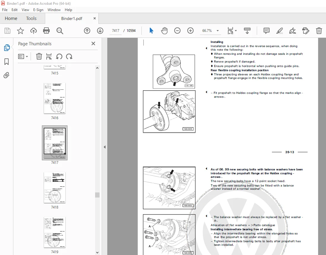
1 Propshaft 1346
1 1 Assembly overview – repairing propshaft 1346
1 2 Removing and installing propshaft 1351
1 3 Removing and installing front flexible coupling 1356
1 4 Removing and installing rear flexible coupling 1358
2 Haldex coupling 1363
2 1 Checking function of Haldex coupling 1363
2 2 Checking oil level or changing oil in Haldex coupling 1363
2 3 Changing oil filter for Haldex coupling 1366
3 Modifying gearbox support -VW 353- 1367
4 Checking gear oil in rear final drive and topping up 1368
5 Removing and installing rear final drive 1369
6 Renewing propshaft flange oil seal on rear final drive (final drive removed) 1373
7 Renewing flange shaft oil seals (final drive installed) 1376
8 Renewing O-ring between Haldex coupling and pinion housing (final drive removed) 1378
9 Renewing O-rings for rear final drive housing cover (final drive installed) 1381
10 Dismantling and assembling rear final drive 1382
10 1 Assembly overviews – rear final drive 1382
10 2 Removing and installing cover for Haldex coupling and plates 1383
10 3 Removing and installing pinion housing 1384
10 4 Removing and installing differential and bevel gear with stub shaft 1386
10 5 Removing and installing cover for Haldex coupling from plate housing 1388
10 6 Assembly overview – Removing and installing Haldex coupling cover with plate housing, set of plates, pinion housing with shaft bevel gear, bevel gear with stub shaft and differential 1391
11 Dismantling and assembling differential 1403
11 1 Assembly overview – differential 1403
12 Repair shaft bevel gear mounting 1412
12 1 Assembly overview – bevel gear mounting 1412
12 2 Assembly sequence – bevel gear mounting 1413
13 Repairing bearings for bevel gear with stub shaft 1421
13 1 Assembly overview – bearings for bevel gear with stub shaft 1421
13 2 Assembly sequence – bearings for bevel gear with stub shaft 1423
14 Adjusting shaft bevel gear and bevel gear with stub shaft (final drive gear set) 1429
14 1 General notes 1429
14 2 Adjustment and marking of final drive gear sets 1429
14 3 Position of shims 1430
14 4 Adjustment overview – rear final drive 1430
14 5 Recommended sequence for new adjustment of final drive gear set 1431
14 6 Adjusting shaft bevel gear 1431
14 7 Adjusting bevel gear (with stub shaft) 1436
39 – Final drive – front differential 1441
1 Renewing oil seals for flange shafts or right-hand drive flange (gearbox installed) 1441
1 1 Renewing oil seal for left flange shaft 1441
1 2 Renewing oil seal for flange shaft or right drive flange 1442
2 Renewing bevel box output flange oil seal (bevel box removed) 1445
3 Dismantling and assembling differential 1447
3 1 Assembly overview – differential 1447
3 2 Assembly sequence – differential 1448
4 Adjustment overview 1452
5 Adjusting differential 1453
6 Dismantling and assembling bevel box 1455
6 1 Bevel box – assembly overview 1455
6 2 Assembly sequence – bevel box 1458
7 Renewing needle bearing (polygon bearing) for right output shaft or for right flange shaft 1470
8 Adjusting shaft bevel gear and bevel gear with stub shaft (final drive gear set) 1474
8 1 General notes 1474
8 2 Adjustment and marking of final drive gear sets 1474
8 3 Position of shims 1475
8 4 Adjustment overview – bevel box 1475
8 5 Recommended sequence for new adjustment of final drive gear set 1476
8 6 Determining shim “S4” thickness when renewing output flange 1476
8 7 Adjusting shaft bevel gear 1477
8 8 Adjusting bevel gear (with stub shaft) 1482
D3E8049715C Wheels and Tyres Guide 1487
00 – Technical data 1495
1 General notes on wheels and tyres (passenger cars) 1495
1 1 Legislative conditions for converting wheel and tyre combinations 1496
1 2 Technical conditions for converting wheel and tyre combinations 1497
1 3 Official type designations 1497
1 3 1 Official type approval, sales or trade designation 1497
1 4 General information 1499
1 4 1 Special models 1499
1 4 2 Vehicles with Plus running gear 1499
1 4 3 Speed ratings for tyres 1500
1 4 4 “Series 80” tyres 1501
1 4 5 Wheel bolts – torque settings 1501
1 4 6 Revised wheel bolts for Sharan from model year 2001 1501
1 4 7 Wheel rims – pitch circle diameter 1502
1 4 8 Data on wheel rims 1502
1 4 9 Split rim wheels 1503
1 4 10 Alloy wheels with exchangeable trim elements 1503
2 Facts about wheels and tyres (passenger cars) 1504
2 1 Tyre wear/ mileage 1504
2 1 1 General information 1504
2 1 2 Requirements to be met by tyres 1504
2 1 3 Wear behaviour of high-speed tyres 1505
2 1 4 Factors influencing the service life of a tyre 1505
2 1 5 Driving style 1506
2 1 6 Tyre maintenance 1507
2 1 7 Evenly worn tyres 1508
2 1 8 Measuring tread depth 1508
2 1 9 One-sided wear 1509
2 1 10 Wear in middle of tyre 1511
2 1 11 Diagonal washout 1512
2 2 Tyre noise 1513
2 2 1 General notes on tyre noise 1513
2 2 2 Saw-tooth wear 1514
2 2 3 Flat spots (from locking wheels) 1515
2 3 Rough running caused by wheels/tyres 1516
2 3 1 Causes of rough running 1516
2 3 2 Balancing wheels 1516
2 3 3 Conducting a road test before balancing wheels 1516
2 3 4 Balancing wheels on stationary wheel balancing machine 1517
2 3 5 Vibration control system -VAS 6230- 1518
2 3 6 Finish balancer 1519
2 3 7 Radial and lateral runout of wheels and tyres 1520
2 3 8 Checking radial and lateral runout on wheels and tyres with tyre gauge -V A G 1435- 1520
2 3 9 Checking radial and lateral runout on wheel 1522
2 3 10 Matching 1522
2 3 11 Flat spots caused by storage or handling 1524
2 4 Vehicle pulls to one side 1525
2 4 1 General information 1525
2 4 2 Conicity 1525
2 4 3 Remedies when vehicle pulls to one side 1527
2 4 4 Strategic rotation of wheels for non-directional tyres 1528
2 4 5 Strategic rotation of wheels having unidirectional tyres 1529
2 4 6 Tyres with a red spot 1529
2 5 Tyre damage 1530
2 5 1 General information 1530
2 5 2 Construction of a radial belted tyre 1531
2 5 3 Impact damage 1531
2 5 4 Cuts 1533
2 5 5 Damage caused by foreign bodies 1533
2 5 6 Loss of air from tyre 1534
2 5 7 Tyre pressure 1534
2 5 8 Tyre damage due to insufficient tyre pressure 1534
2 5 9 Rising tyre temperature caused by insufficient inflation pressure 1536
2 5 10 Tyre damage due to fitting error (fitting damage) 1537
2 6 Facts about wheels and tyres 1539
2 6 1 Identification markings on the tyre sidewall 1539
2 6 2 Explanation of tyre markings 1541
2 6 3 Undulations 1542
2 6 4 The valve 1543
2 6 5 Tyre storage 1544
2 6 6 Tyre ageing 1544
2 6 7 Care and maintenance of alloy wheel rims 1545
2 6 8 Rotating wheels 1546
2 6 9 Instructions for changing or fitting wheels 1546
2 6 10 Tyres with flange protection 1547
2 6 11 Notes on use of temporary spare wheels 1548
2 6 12 M+S tyres 1549
2 6 13 Winter tyres with speed symbol “V” 1550
2 6 14 Extra Load (XL) V winter tyres 1550
2 6 15 Reinforced and Extra Load (XL) tyres 1553
2 6 16 Snow chains 1553
44 – Wheels, tyres, vehicle geometry 1554
1 Lupo 3L, Lupo FSI, Lupo GTI from model year 1999 1554
1 1 Lupo 3L, type 6E model year 1999 to model year 2006 1554
1 2 Wheel allocation for Lupo 3L, type 6E model year 1999 to model year 2006 1555
1 2 1 4 J x 14 1555
1 2 2 41/2 J x 14 1556
1 2 3 5 J x 14 1556
1 3 Lupo FSI, type 6E model year 2001 to model year 2006 1556
1 4 Wheel allocation for Lupo FSI, type 6E model year 2001 to model year 2006 1557
1 4 1 5 J x 14 1557
1 4 2 6 J x 14 1558
1 5 Lupo GTI, type 6ES model year 2001 to model year 2006 1560
1 6 Wheel allocation for Lupo GTI, type 6ES model year 2001 to model year 2006 1561
1 6 1 6 J x 14 1561
1 6 2 61/2 J x 15 1562
2 Lupo model year 1999 to model year 2005 1564
2 1 Lupo, type 6X model year 1999 to model year 2005 1564
2 2 Wheel allocation for Lupo, type 6X model year 1999 to model year 2005 1566
2 2 1 41/2 J x 13 1566
2 2 2 51/2 J x 13 1567
2 2 3 6 J x 14 1569
2 2 4 6 J x 15 1572
3 Fox model year 2006 1574
3 1 Fox, type 5Z model year 2006 1574
3 2 Wheel allocation for Fox, type 5Z model year 2006 1575
3 2 1 5 J x 14 1575
3 2 2 6 J x 14 1576
3 2 3 6 J x 15 1578
4 Polo model year 1995 to model year 2002 1581
4 1 Polo, type 6N up to and including 07 95 1581
4 2 Wheel allocation for Polo, type 6N up to and including 07 95 1582
4 2 1 41/2 J x 13 1582
4 2 2 51/2 J x 13 1583
4 3 Polo, type 6N from 08 95 up to and including model year 1996 1584
4 4 Polo, type 6N from model year 1997 to model year 1999 1585
4 5 Wheel allocation for Polo, type 6N from 08 95 to model year 1999 1587
4 5 1 41/2 J x 13 1587
4 5 2 51/2 J x 13 1588
4 5 3 6 J x 14 1589
4 5 4 6 J x 15 1591
4 6 Polo, type 6N from model year 2000 to model year 2002 1593
4 7 Wheel allocation for Polo, type 6N from model year 2000 to model year 2002 1594
4 7 1 41/2 J x 13 1594
4 7 2 51/2 J x 13 1595
4 7 3 6 J x 14 1596
4 7 4 6 J x 15 1598
5 Polo from model year 2002 1601
5 1 Polo, type 9N model year 2002 to model year 2006 1601
5 2 Wheel allocation for Polo, type 9N model year 2002 to model year 2006 1603
5 2 1 5 J x 13 1604
5 2 2 5 J x 14 1604
5 2 3 6 J x 14 1605
5 2 4 6 J x 15 1606
5 2 5 61/2 J x 16 1608
6 Polo Fun from model year 2004 1612
6 1 Polo Fun, type 9N model year 2002 to model year 2006 1612
6 2 Wheel allocation for Polo Fun, type 9N model year 2004 to model year 2006 1613
6 2 1 6 J x 15 1613
6 2 2 71/2 J x 17 1614
7 Polo Classic model year 1996 to model year 2002 1615
7 1 Polo Classic, type 6KV model year 1996 to model year 2002 1615
7 2 Wheel allocation for Polo Classic, type 6KV model year 1996 to model year 2002 1617
7 2 1 51/2 J x 13 1617
7 2 2 6 J x 14 1618
7 2 3 6 J x 15 1620
8 Polo estate model year 1998 to model year 2002 1622
8 1 Polo estate type 6KV model year 1998 to model year 2002 1622
8 2 Wheel allocation for Polo estate type 6KV model year 1998 to model year 2002 1624
8 2 1 51/2 J x 13 1624
8 2 2 6 J x 14 1625
8 2 3 6 J x 15 1627
9 Polo saloon/sedan model year 2004 to model year 2005 1629
9 1 Polo saloon/sedan, type 9N model year 2004 to model year 2005 1629
9 2 Wheel allocation for Polo saloon/sedan, type 9N model year 2004 to model year 2005 1631
9 2 1 5 J x 14 1631
9 2 2 6 J x 14 1631
9 2 3 6 J x 15 1633
9 2 4 61/2 J x 16 1635
10 Golf model year 1992 to model year 1998 1637
10 1 Golf type 1HX0, Golf Syncro 1HX1, Golf type 1H 1637
10 2 Wheel allocation for Golf type 1HX0, Golf Syncro 1HX1, Golf type 1H 1640
10 2 1 51/2 J x 13 1641
10 2 2 6 J x 14 1642
10 2 3 6 J x 15 1646
10 2 4 61/2 J x 15 1650
10 2 5 7 J x 16 1654
11 Golf model year 1998 to model year 2004, Golf R32, Golf Anniversary GTI 1655
11 1 Golf, Golf 4Motion, type 1J model year 1998 to model year 2004 1655
11 2 Wheel allocation for Golf, Golf 4Motion, type 1J model year 1998 to model year 2004 1658
11 2 1 6 J x 14 1658
11 2 2 6 J x 15 1659
11 2 3 51/2 J x 16 1664
11 2 4 61/2 J x 16 1665
11 2 5 7 J x 17 1671
11 2 6 71/2 J x 17 1674
11 3 Conditions for fitting 17″ wheels and tyres to Golf model year 1998 to model year 2004 1674
11 4 Golf R32, type 1J model year 2003 to model year 2005 1675
11 5 Wheel allocation for Golf R32, type 1J model year 2003 to model year 2005 1676
11 5 1 51/2 J x 17 1676
11 5 2 71/2 J x 17 1677
11 5 3 71/2 J x 18 1678
11 6 Golf Anniversary GTI, type 1J model year 2002 1678
11 7 Wheel allocation for Golf Anniversary GTI, type 1J model year 2002 1679
11 7 1 51/2 J x 16 1679
11 7 2 61/2 J x 16 1680
11 7 3 7 J x 17 1682
11 7 4 71/2 J x 18 1684
11 8 Conditions for fitting 17″ and 18″ wheels and tyres of Golf Anniversary GTI 1685
12 Golf from model year 2004 1687
12 1 Golf, Golf 4Motion, type 1K model year 2004 to model year 2006 1687
12 2 Wheel allocation for Golf, Golf 4Motion, type 1K model year 2004 to model year 2006 1689
12 2 1 6 J x 15 1689
12 2 2 61/2 J x 15 1690
12 2 3 6 J x 16 1691
12 2 4 61/2 J x 16 1692
12 2 5 7 J x 17 1694
12 2 6 71/2 J x 17 1697
12 2 7 71/2 J x 18 1697
12 3 Golf GTI, type 1K model year 2005 to model year 2006 1698
12 4 Wheel allocation for Golf GTI, type 1K model year 2005 to model year 2006 1699
12 4 1 6 J x 16 1699
12 4 2 61/2 J x 16 1700
12 4 3 6 J x 17 1701
12 4 4 7 J x 17 1702
12 4 5 71/2 J x 17 1705
12 4 6 71/2 J x 18 1705
13 Golf Plus from model year 2005 1707
13 1 Golf Plus, type 1KP model year 2005 to model year 2006 1707
13 2 Wheel allocation for Golf Plus, type 1KP model year 2005 to model year 2006 1709
13 2 1 6 J x 15 1709
13 2 2 61/2 J x 15 1710
13 2 3 6 J x 16 1711
13 2 4 61/2 J x 16 1712
13 2 5 7 J x 17 1714
13 2 6 71/2 J x 18 1717
14 Golf estate model year 1994 to model year 1998 1719
14 1 Golf estate type 1HX0, Golf estate Syncro type 1HX1, Golf estate type 1H 1719
14 2 Wheel allocation for Golf estate type 1HX0, Golf estate Syncro type 1HX1, Golf estate type 1H 1722
14 2 1 51/2 J x 13 1722
14 2 2 6 J x 14 1723
14 2 3 6 J x 15 1728
14 2 4 61/2 J x 15 1732
15 Golf estate model year 1999 to model year 2006, Bora estate model year 1999 to model year 2005 1733
15 1 Golf estate, Golf estate 4Motion, Bora estate, Bora estate 4Motion, type 1J 1733
15 2 Wheel allocation for Golf estate, Golf estate 4Motion, Bora estate, Bora estate 4Motion, type 1J 1736
15 2 1 6 J x 15 1736
15 2 2 51/2 J x 16 1740
15 2 3 61/2 J x 16 1741
15 2 4 7 J x 17 1747
15 2 5 71/2 J x 17 1750
15 3 Conditions for fitting 17″ wheels and tyres 1751
16 Golf cabriolet model year 1994 to model year 1997 1753
16 1 Golf cabriolet type 1EX0 model year 1994 to model year 1997 1753
16 2 Wheel allocation for Golf cabriolet, type 1EX0 from model year 1994 to model year 1997 1754
16 2 1 6 J x 14 1755
16 2 2 6 J x 15 1756
16 2 3 61/2 J x 16 1757
17 Golf cabriolet model year 1998 to model year 2002 1759
17 1 Golf cabriolet; type 1E from model year 1998 to model year 2002 1759
17 2 Wheel allocation for Golf cabriolet; type 1E from model year 1998 to model year 2002 1760
17 2 1 6 J x 14 1760
17 2 2 6 J x 15 1763
17 2 3 61/2 J x 16 1765
18 Vento from model year 1992 to model year 1998 1766
18 1 Vento; type 1HX0, 1H 1766
18 2 Wheel allocation for Vento; type 1HX0, 1H 1768
18 2 1 51/2 J x 13 1768
18 2 2 6 J x 14 1770
18 2 3 6 J x 15 1773
18 2 4 61/2 J x 15 1776
19 Bora model year 1999 to model year 2005 1782
19 1 Bora, Bora 4Motion, type 1J model year 1999 to model year 2005 1782
19 2 Wheel allocation for Bora, Bora 4Motion, type 1J model year 1999 to model year 2005 1785
19 2 1 6 J x 15 1785
19 2 2 51/2 J x 16 1789
19 2 3 61/2 J x 16 1790
19 2 4 7 J x 17 1796
19 2 5 71/2 J x 17 1799
19 3 Conditions for fitting 17″ wheels and tyres 1800
20 Jetta from model year 2006 1802
20 1 Jetta, type 1KM from model year 2006 1802
20 2 Wheel allocation for Jetta, type 1KM from model year 2006 1804
20 2 1 6 J x 15 1804
20 2 2 61/2 J x 15 1805
20 2 3 6 J x 16 1805
20 2 4 61/2 J x 16 1806
20 2 5 7 J x 17 1808
21 New Beetle from model year 1999 1812
21 1 New Beetle, type 9C model year 1999 to model year 2006 1812
21 2 Wheel allocation for New Beetle, type 9C model year 1999 to model year 2006 1815
21 2 1 6 J x 15 1815
21 2 2 51/2 J x 16 1818
21 2 3 61/2 J x 16 1819
21 2 4 7 J x 17 1824
21 2 5 71/2 J x 17 1827
21 3 Conditions for fitting 17″ wheels and tyres 1828
22 New Beetle Cabriolet from model year 2003 1830
22 1 New Beetle Cabriolet, type 1Y, model year 2003 to model year 2006 1830
22 2 Wheel allocation for New Beetle Cabriolet, type 1Y model year 2003 to model year 2006 1832
22 2 1 6 J x 15 1832
22 2 2 51/2 J x 16 1835
22 2 3 61/2 J x 16 1836
22 2 4 7 J x 17 1840
22 2 5 71/2 J x 17 1844
22 3 Conditions for fitting 17″ wheels and tyres 1844
23 New Beetle RSi 1846
23 1 New Beetle RSi, type 9CR from model year 2001 1846
23 2 Wheel allocation for New Beetle RSi, type 9CR from model year 2001 1847
23 2 1 7 J x 16 1847
23 2 2 9 x 18 1848
24 Touran from model year 2003 1849
24 1 Touran, type 1T, model year 2003 to model year 2006 1849
24 2 Wheel allocation for Touran, type 1T model year 2003 to model year 2006 1852
24 2 1 6 J x 15 1852
24 2 2 61/2 J x 15 1853
24 2 3 6 J x 16 1854
24 2 4 61/2 J x 16 1855
24 2 5 7 J x 17 1857
25 Passat model year 1994 to model year 1997 1858
25 1 Passat, type 35l model year 1994 to model year 1997 1858
25 2 Wheel allocation for Passat, type 35l model year 1994 to model year 1997 1860
25 2 1 6 J x 14 1860
25 2 2 6 J x 15 1863
26 Passat model year 1997 to model year 2006 1868
26 1 Passat, Passat estate, type 3B model year 1997 to model year 2000 1868
26 2 Passat, Passat estate, type 3B model year 1997 to model year 2000 1870
26 2 1 6 J x 15 1870
26 2 2 7 J x 15 1872
26 2 3 7 J x 16 1873
26 3 Passat, Passat estate, type 3BG model year 2001 to model year 2006 1874
26 4 Wheel allocation for Passat, Passat estate, type 3BG model year 2001 to model year 2006 1876
26 4 1 6 J x 15 1876
26 4 2 7 J x 15 1877
26 4 3 6 J x 16 1879
26 4 4 7 J x 16 1880
26 4 5 7 J x 17 1882
26 5 Passat W8 4Motion, type 3BS model year 2002 to model year 2005 1883
26 6 Wheel allocation for Passat W8 4Motion, type 3BS model year 2002 to model year 2005 1884
26 6 1 7 J x 16 1885
26 6 2 6 J x 17 1885
26 6 3 71/2 J x 17 1886
26 7 Passat Protect, type 3BL model year 2002 to model year 2005 1886
26 8 Wheel allocation for Passat Protect, type 3BL model year 2002 to model year 2005 1887
26 8 1 6 J x 16 1888
26 8 2 7 J x 16 1888
27 Passat from model year 2006 1890
27 1 Passat, type 3C from model year 2006 1890
27 2 Wheel allocation for Passat, type 3C from model year 2006 1892
27 2 1 61/2 J x 16 1893
27 2 2 7 J x 16 1893
27 2 3 6 J x 17 1895
27 2 4 71/2 J x 17 1895
27 2 5 8 J x 18 1898
28 Phaeton from model year 2003 1900
28 1 Phaeton, type 3D, model year 2003 to model year 2006 – short and long wheelbase 1900
28 2 Wheel allocation for Phaeton, type 3D model year 2003 to model year 2006 – short and long wheelbase 1902
28 2 1 71/2 J x 16 1903
28 2 2 71/2 J x 17 1903
28 2 3 71/2 J x 18 1905
28 2 4 81/2 J x 18 1905
28 2 5 81/2 J x 19 1907
28 2 6 9 J x 19 1907
29 Sharan from model year 1996 1908
29 1 Sharan, Sharan Syncro, type 7M model year 1996 to model year 2000 1908
29 2 Wheel allocation for Sharan, Sharan Syncro Type 7M model year 1996 to model year 2000 1911
29 2 1 6 J x 15 1911
29 2 2 7 J x 15 1911
29 2 3 7 J x 16 1912
29 3 Sharan, Sharan 4Motion, type 7M model year 2001 1913
29 4 Wheel allocation for Sharan, Sharan 4Motion, type 7M model year 2001 1915
29 4 1 6 J x 15 1915
29 4 2 7 J x 15 1916
29 4 3 6 J x 16 1917
29 4 4 7 J x 16 1918
29 5 Sharan, Sharan 4Motion, type 7M model year 2002 to model year 2006 1921
29 6 Wheel allocation for Sharan, Sharan 4Motion, type 7M model year 2002 to model year 2006 1923
29 6 1 6 J x 16 1923
29 6 2 7 J x 16 1924
29 6 3 7 J x 17 1927
30 Touareg from model year 2003 1928
30 1 Touareg, type 7L, model year 2003 to model year 2006 1928
30 2 Wheel allocation for Touareg, type 7L model year 2003 to model year 2006 1931
30 2 1 7 J x 16 1931
30 2 2 71/2 J x 17 1932
30 2 3 8 J x 18 1933
30 2 4 9 J x 19 1936
30 2 5 9 J x 20 1940
30 2 6 91/2 J x 20 1941
31 Breakdown set for VW Vehicles 1942
32 Temporary spare tyres and wheels for VW vehicles 1943
33 Approved makes of summer tyres for initial fitting 1946
33 1 Summer tyres for Lupo 3L from model year 1999 1946
33 2 Summer tyres for Lupo FSI from model year 1999 1946
33 3 Summer tyres for Lupo GTI from model year 1999 1946
33 4 Summer tyres for Lupo model year 1999 to model year 2005 1946
33 5 Summer tyres for Fox from model year 2006 1946
33 6 Summer tyres for Polo, model year 1995 to model year 2002 1947
33 7 Summer tyres for Polo from model year 2002 1948
33 8 Summer tyres for Polo saloon/sedan from model year 2004 1948
33 9 Summer tyres for Polo Fun from model year 2004 1949
33 10 Summer tyres for Polo Classic model year 1996 to model year 2002 1949
33 11 Summer tyres for Polo estate model year 1998 to model year 2002 1950
33 12 Summer tyres for Golf, Vento model year 1992 to model year 1998 1950
33 13 Summer tyres for Golf estate model year 1994 to model year 1998 1951
33 14 Summer tyres for Golf cabriolet model year 1994 to model year 1997 1951
33 15 Summer tyres for Golf, Golf 4Motion model year 1998 to model year 2004 1952
33 16 Summer tyres for Bora, Bora 4Motion model year 1999 to model year 2005 1953
33 17 Summer tyres for Golf estate, Golf estate 4Motion model year 1999 to model year 2006, Bora estate, Bora estate 4Motion model year 1999 to model year 2005 1954
33 18 Summer tyres for Golf R32 1954
33 19 Summer tyres for Golf Anniversary GTI 1955
33 20 Summer tyres for Golf Cabriolet, model year 1998 to model year 2002 1955
33 21 Summer tyres for New Beetle from model year 1999 1956
33 22 Summer tyres for New Beetle Cabriolet from model year 2003 1957
33 23 Summer tyres for New Beetle RSi 1958
33 24 Summer tyres for Golf from model year 2004 1958
33 25 Summer tyres for Golf GTI from model year 2005 1959
33 26 Summer tyres for Golf Plus from model year 2005 1959
33 27 Summer tyres for Jetta from model year 2006 1960
33 28 Summer tyres for Touran from model year 2003 1960
33 29 Summer tyres for Passat model year 1994 to model year 1997 1961
33 30 Summer tyres for Passat model year 1997 to model year 2006 1961
33 31 Summer tyres for Passat W8 1962
33 32 Summer tyres for Passat Protect 1962
33 33 Summer tyres for Passat from model year 2006 1962
33 34 Summer tyres for Phaeton from model year 2003 1963
33 35 Summer tyres for Sharan from model year 1996 1963
33 36 Summer tyres for Touareg from model year 2003 1964
34 Approved makes of all-season tyres for initial fitting 1965
34 1 All-season tyres for Lupo, model year 1999 to model year 2005 1965
34 2 All-season tyres Polo model year 1995 to model year 2002 1965
34 3 All-season tyres from model year 2002 1965
34 4 Summer tyres for Polo saloon/sedan from model year 2004 1965
34 5 All-season tyres Golf, Vento model year 1992 to model year 1998 1965
34 6 All-season tyres Golf estate model year 1994 to model year 1998 1965
34 7 All-season tyres Golf cabriolet model year 1994 to model year 1997 1966
34 8 All-season tyres Golf, Golf 4Motion model year 1998 to model year 2004 1966
34 9 All-season tyres Bora, Bora 4Motion model year 1999 to model year 2005 1966
34 10 All-season tyres Golf estate, Golf estate 4Motion model year 1999 to model year 2006, Bora estate, Bora estate 4Motion model year 1999 to model year 2005 1967
34 11 All-season tyres Golf cabriolet model year 1998 to model year 2002 1967
34 12 All-weather tyres New Beetle from model year 1999 1967
34 13 All-weather tyres New Beetle Cabriolet from model year 2003 1967
34 14 All-weather tyres Golf from model year 2004 1968
34 15 All-season tyres for Golf Plus from model year 2005 1968
34 16 All-season tyres for Jetta from model year 2006 1968
34 17 All-weather tyres Touran from model year 2003 1969
34 18 All-season tyres for Passat, model year 1997 to model year 2006 1969
34 19 All-season tyres for Passat W8 1969
34 20 All-weather tyres Passat from model year 2006 1969
34 21 All-weather tyres Phaeton from model year 2003 1970
34 22 All-weather tyres Touareg from model year 2003 1970
35 Approved makes of winter tyres for initial fitting 1971
35 1 Winter tyres for Lupo 3L from model year 1999 1971
35 2 Winter tyres for Lupo FSI from model year 1999 1971
35 3 Winter tyres for Lupo GTI from model year 1999 1971
35 4 Winter tyres Lupo model year 1999 to model year 2005 1971
35 5 Winter tyres for Fox from model year 2006 1971
35 6 Winter tyres for Polo model year 1995 to model year 2002 1972
35 7 Winter tyres Polo from model year 2002 1972
35 8 Summer tyres for Polo saloon/sedan from model year 2004 1972
35 9 Summer tyres for Polo Fun from model year 2004 1973
35 10 Winter tyres Polo Classic model year 1996 to model year 2002 1973
35 11 Winter tyres Polo estate model year 1998 to model year 2002 1973
35 12 Winter tyres Golf, Vento model year 1992 to model year 1998 1974
35 13 Winter tyres Golf estate model year 1994 to model year 1998 1974
35 14 Winter tyres Golf cabriolet model year 1994 to model year 1997 1974
35 15 Winter tyres Golf, Golf 4Motion model year 1998 to model year 2004 1975
35 16 Winter tyres Bora, Bora 4Motion model year 1999 to model year 2005 1975
35 17 Winter tyres Golf estate, Golf estate 4Motion model year 1999 to model year 2006, Bora estate, Bora estate 4Motion model year 1999 to model year 2005 1976
35 18 Winter tyres for Golf R32 1976
35 19 Winter tyres for Golf Anniversary GTI 1976
35 20 Winter tyres Golf cabriolet model year 1998 to model year 2002 1976
35 21 Winter tyres New Beetle from model year 1999 1977
35 22 Winter tyres New Beetle Cabriolet from model year 2003 1977
35 23 Winter tyres for New Beetle RSi 1978
35 24 Winter tyres Golf from model year 2004 1978
35 25 Winter tyres for Golf GTI from model year 2005 1978
35 26 Winter tyres for Golf Plus from model year 2005 1978
35 27 Winter tyres for Jetta from model year 2006 1978
35 28 Winter tyres Touran from model year 2003 1979
35 29 Winter tyres for Passat model year 1994 to model year 1997 1979
35 30 Winter tyres for Passat model year 1997 to model year 2006 1979
35 31 Winter tyres for Passat W8 1980
35 32 Winter tyres for Passat Protect 1980
35 33 Winter tyres Passat from model year 2006 1980
35 34 Winter tyres Phaeton from model year 2003 1980
35 35 Winter tyres Sharan from model year 1996 1981
35 36 Winter tyres Touareg from model year 2003 1981
36 Approved makes of offroad tyres for initial fitting 1982
36 1 Offroad tyres for Touareg from model year 2003 1982
D4B807E3B5B Body Repairs General Body Repairs 1983
1 Safety instructions 1987
1 1 Part removal 1987
1 2 Battery and welding operation 1987
1 3 Electronic control unit 1987
1 3 1 Processing of the electronic control unit after repair dueto a traffic accident 1987
1 4 Paint, glass, soft pad and trim 1988
1 5 Fuel tank or fuel delivery pipeline 1988
1 6 Air conditioner 1988
1 6 1 Remedial measures: 1988
1 7 Airbag System 1989
1 8 Check the seat belts 1989
1 8 1 Belt body 1990
1 8 2 Automatic retractor (locking function) 1990
1 8 3 Visual inspection of the seat belt buckle 1991
1 8 4 Seat belt buckle function 1991
1 8 5 Seat belt guide member and tongue 1992
1 8 6 Fixing piece and fixing point 1992
1 9 Safety specifications for the seat belt tensioner 1992
1 10 Body repair on a vehicle equipped with the seat belt tensioners 1993
1 10 1 The following vehicles have been equipped with: 1993
1 11 Perform cutting off, correcting and/or leveling on a vehicleequipped with airbags 1994
1 12 Remove the front seats with a side airbag 1994
2 Basic instruction 1995
2 1 Diagnosis of the accident vehicle 1995
2 2 Condition of the body and/or the parts for delivery to thepainting workshop 1995
2 3 Correction 1995
2 4 Cutting 1995
2 5 Body-cut part and part section 1995
2 6 Original connection 1996
2 7 Galvanized body parts 1996
2 8 Remove the rest part 1996
2 9 New parts 1996
2 10 Parts 1996
2 11 Molded foam plastic pads 1997
3 Symbolic interpretation 1998
3 1 Symbolic interpretation for welding 1998
3 2 Symbolic interpretation for the operation method 1998
3 2 1 Grinding 1999
3 2 2 Thinning 1999
3 2 3 Punching 1999
3 2 4 Drilling 2000
3 2 5 Polishing 2000
3 2 6 Cavity corrosion protection 2000
3 2 7 Bonding 2001
3 2 8 Precise sealing 2001
4 Body repair tools 2002
4 1 Flaring tool -V A G 1317- 2002
4 2 Punching pliers -V A G 1329- 2002
4 3 Basic equipment -V A G 1366/3- 2002
4 4 Bottom protection layer spray gun -V A G 1379- 2003
4 5 Electric blower -V A G 1416- 2003
4 6 Door tensioner -V A G 1438- 2003
4 7 Body equipment component -V A G 1439- 2004
4 8 Pneumatic cutting knife -V A G 1523 A- 2004
4 9 Air chisel -V A G 1577- 2004
4 10 Edge closing iron block -V A G 1585- 2005
4 11 Welding fume ventilator -V A G 1586- 2005
4 12 Welding spot releasing device -V A G 1731- 2005
4 13 Pneumatic spray gun -V A G 1761/1- 2006
4 14 Pneumatic punching and thinning pliers -VAS 1996- 2006
4 15 Pneumatic adhesive spray gun -V A G 2005- 2006
4 16 Door hinge correction tool 2007
4 17 Hose kit 5023 for the inert gas protection welding 2007
4 18 Angle grinder -VAS 5174- 2007
4 19 Angle grinder -VAS 5175- 2008
4 20 Wire brush -VAS 5182- 2008
5 Body bonding 2009
5 1 Transporter 1991 → 2009
5 1 1 Separation process: 2009
5 1 2 Bonding process: 2009
5 2 Bonding types 2009
5 2 1 Bonding-strong 2009
5 2 2 Bonding-spot welding 2010
5 3 Repair method for replacing the parts 2010
5 3 1 Spot welding and bonding 2010
5 3 2 Plug welding and bonding (if spot welding is impossible) 2010
5 3 3 Welding fume ventilator 2011
5 3 4 Preparations 2011
5 3 5 Trimming 2011
6 Corrosion protection measures 2012
6 1 Corrosion protection 2012
7 Waste disposal instructions 2013
7 1 Waste disposal 2013
7 2 Air pressure tappet exhaust 2013
7 3 Airbag 2014
7 3 1 Waste disposal 2014
8 Contact corrosion protection 2015
8 1 Connection of aluminum alloy/magnesium alloy with steel 2015
9 Steel plate repair 2016
9 1 High-strength body plate 2016
9 2 Galvanized body parts 2016
9 2 1 Preparations 2016
9 2 2 Part cutting 2017
9 2 3 Connection process 2017
9 3 Welding on the galvanized body steel plate 2017
9 3 1 Inert gas protection plug welding SG of the galvanized steelplate 2017
9 3 2 Resistance pressure spot welding RP of the galvanized steelplate 2018
9 3 3 Welding transformer 2018
9 3 4 Welding clamp 2018
9 4 Tearing test 2018
10 Aluminum repair 2019
10 1 Painting 2019
10 2 Surface treatment 2019
10 3 Leveling 2020
10 4 Temperature control for heating 2020
11 Plastic repair method 2021
11 1 Material 2021
11 2 Repairing the pit 2022
11 3 Repairing the scratch 2023
11 4 Repair the crack 2025
11 5 Repairing the small hole (the diameter is more than 30 mm) 2026
11 6 Plastic repair (glass fibre material) 2027
11 7 Repair process 2028
11 7 1 Repairing the breakage position 2028
11 7 2 Repairing the surface damage 2030
12 Glass repair 2031
12 1 Repairing the windshield 2031
12 1 1 Premises 2031
12 1 2 Required special tools, operating equipment, testing instrumentsand auxiliary tools 2032
12 1 3 Repair description 2033
D4B806742B7 Gas drive General information 2037
00 – Technical data 2041
1 Safety information 2041
1 1 Safety precautions when working on natural gas system 2041
2 General information 2042
2 1 Other reference material 2042
3 Safety briefing/employee qualification 2043
3 1 Safety briefing/employee qualification 2043
4 Receiving vehicles for repair 2045
4 1 Procedure for taking receipt of vehicles 2045
5 Laws and regulations 2046
5 1 Rules and regulations 2046
5 2 Workplace requirements 2046
6 Basic technical and physical principles 2047
6 1 Physical properties 2047
6 1 1 Physical data of dried natural gas 2047
7 Repair instructions 2048
7 1 Rules for cleanliness 2048
8 Checking natural gas system 2049
8 1 Test requirements for gas systems 2049
8 1 1 Testing with self-diagnosis 2049
8 2 Checking natural gas system for leaks 2049
8 3 Searching for leaks in gas system using gas leak detector 2049
8 4 Searching for leaks in gas system using leak detector spray 2051
20 – Fuel supply system 2052
1 Fuel 2052
1 1 Handling natural gas fuel tanks 2052
1 2 Storing natural gas fuel tanks 2052
1 3 Damage assessment catalogue for natural gas fuel tanks 2054
1 3 1 Damage assessment of steel fuel tanks 2054
1 3 2 Damage assessment of carbon fibre fuel tank (composition fibre reinforced fuel tank) 2054
1 4 Discharging natural gas fuel tanks 2057
1 5 Rendering natural gas fuel tanks inert 2069
1 5 1 With water: 2069
1 5 2 With nitrogen: 2069
1 6 Disposing of natural gas fuel tanks 2070
1 7 Determining residual pressure in natural gas fuel tank 2070
1 7 1 Checking and converting adapter for back-pressure test on natural gas tank 2070
1 7 2 Checking (self test) cooling system tester 2072
1 7 3 Determining residual pressure in natural gas fuel tank 2078
1 8 Reducing fuel pressure in high-pressure section 2083
1 8 1 Reducing fuel pressure in high-pressure section 2083
2 Senders and sensors 2086
2 1 Gas rail temperature and pressure sensor -GX21- 2086
2 2 High-pressure valve for gas mode -N372- 2086
2 3 Gas rail sensor -G401- (low-pressure side) 2087
2 4 Tank pressure sensor -G400- 2087
24 – Mixture preparation – injection 2088
1 Mixture preparation – injection 2088
1 1 Distinguishing between pressure sections of natural gas supply system 2088
1 1 1 High-pressure section 2088
1 1 2 Low-pressure section 2090
1 2 High-pressure injectors N30 – N33 2091
D4B8027068B Air conditioning systems with refrigerant R134a General information 2093
00 – Technical data 2099
1 Safety information 2099
1 1 Safety precautions when working on air conditioning systems 2099
1 2 Safety precautions when working on high-voltage system 2100
1 3 Safety precautions when working in the vicinity of high-voltage components 2100
1 4 Safety precautions when tow-starting or towing 2101
2 Repair instructions 2102
2 1 Rules for cleanliness when working on high-voltage system 2102
3 General information on air conditioning 2103
3 1 Other reference material 2103
3 2 Basics of air conditioning technology 2103
3 2 1 Physical principles: 2103
3 2 2 Heat always flows from a warmer to a colder substance 2104
3 2 3 Pressure and boiling point 2104
3 3 Vapour pressure table for refrigerant R134a 2105
3 4 Refrigerant R134a 2106
3 4 1 Physical data of refrigerant R134a 2106
3 4 2 Critical point 2106
3 4 3 Environmental aspects of refrigerant R134a 2107
3 5 Properties of refrigerant R134a 2107
3 5 1 Trade names and designations 2107
3 5 2 Colour 2107
3 5 3 Vapour pressure 2107
3 5 4 Physical properties of R134a 2108
3 5 5 Effects on metal 2108
3 5 6 Critical temperature and critical pressure 2108
3 5 7 Union 2108
3 5 8 Charge factor 2108
3 5 9 Detecting leaks 2108
3 6 Refrigerant oil 2109
3 6 1 Properties of refrigerant oil 2109
3 7 Comfort 2110
3 7 1 Environmental aspects 2110
3 8 How air conditioning works 2111
3 9 General work safety 2111
3 9 1 Product characteristics 2111
3 9 2 Handling refrigerants 2112
3 9 3 Wear safety goggles 2112
3 9 4 Wear protective gloves and apron 2112
3 9 5 Do not allow liquid refrigerant to come in contact with the skin 2112
3 9 6 Do not breath in refrigerant vapour 2112
3 9 7 Absolutely NO SMOKING 2112
3 9 8 Welding and soldering on refrigeration systems 2112
3 9 9 Pungent smell 2113
3 9 10 First aid 2113
3 9 11 Handling pressure vessels 2113
3 9 12 Do not heat up above 50°C 2113
3 9 13 Do not expose to uncontrolled heat 2113
3 9 14 Seal empty tanks/containers 2113
3 9 15 Safety instructions for using extraction and charging equipment 2114
3 10 Safety measures when working on vehicles with air conditioning and when working with refrigerant R134a 2114
3 11 Basics for working on refrigerant circuit 2115
3 11 1 O-ring 2116
3 11 2 Before operating the air conditioning system after recharging with refrigerant 2117
4 General information on refrigerant circuit 2118
4 1 Components of refrigerant circuit 2118
4 1 1 Distribution of the refrigerant circuit components and their influence on the high-pressure and low-pressure sides 2118
4 1 2 Air conditioning system compressor with magnetic clutch: 2118
4 1 3 Air conditioner compressor without magnetic clutch 2119
4 1 4 Air conditioner compressor without magnetic clutch, with elastic drive coupling 2120
4 1 5 Electrical air conditioner compressor for high-voltage system 2121
4 1 6 Condenser 2122
4 1 7 evaporator 2122
4 1 8 Reservoir 2123
4 1 9 Restrictor 2123
4 1 10 Receiver 2124
4 1 11 Expansion valve 2125
4 1 12 O-ring 2126
4 1 13 Pipes and hoses of refrigerant circuit 2126
4 1 14 High-pressure safety valve 2126
4 2 Design of refrigerant circuit 2129
4 2 1 Refrigerant circuit with expansion valve and evaporator 2129
4 2 2 Refrigerant circuit with restrictor and reservoir 2129
4 3 Evacuation and charging valves for quick-release couplings of air conditioner service station on refrigerant circuit 2130
4 3 1 Evacuation and charging valve with Schrader valve 2130
4 3 2 Extraction and charging valve, high-pressure side 2131
4 3 3 Extraction and charging valve, low-pressure side 2132
4 4 Switches and senders in refrigerant circuit and related connections 2132
4 4 1 High-pressure switch for air conditioning system -F23- 2132
4 4 2 High-pressure switch for magnetic clutch -F118- 2133
4 4 3 Low-pressure switch for air conditioning system -F73- 2133
4 4 4 Connections with valve for switches in refrigerant circuit 2134
4 4 5 Air conditioning system pressure switch -F129- 2134
4 4 6 High-pressure sender -G65- 2135
4 4 7 Refrigerant pressure and temperature sender -G395- 2136
4 4 8 Air conditioner compressor regulating valve -N280- 2136
4 5 Electrical components not installed in refrigerant circuit 2137
4 5 1 Control and regulating unit for air conditioning system -J127- 2137
4 5 2 Radiator fan control unit -J293- 2137
4 5 3 Radiator fan control unit -J293- 2138
4 5 4 Temperature switch for evaporator -E33- 2139
4 5 5 Evaporator output temperature sender -G263- or evaporator temperature sensor -G308- 2139
4 6 Pressures and temperatures in refrigerant circuit 2140
4 7 Refrigerant circuit with expansion valve 2140
4 8 Refrigerant circuit with restrictor and reservoir 2142
4 9 Test and measurement work that can be performed using a pressure gauge 2144
4 9 1 Pressure gauges enable the following test and measurement work 2144
4 10 Air conditioner service and recycling equipment 2145
4 10 1 Classification of extraction and charging devices in groups 2145
4 10 2 Charging devices that do not require a permit 2145
4 11 Notes to repairs on refrigerant circuit 2146
5 Laws and regulations 2147
5 1 Laws and regulations 2147
5 2 Recycling and refuse law 2152
5 2 1 Disposal of refrigerant and refrigerant machine oil 2152
5 3 Converting R12 refrigerant circuits to R134a refrigerant circuits and servicing them (retrofitting) 2153
5 4 Maintaining records on refrigerant 2153
6 Refrigerant circuit 2154
6 1 Important repair notes on air conditioning 2154
6 2 Converting refrigerant circuits from R12 refrigerant to R134a 2154
7 Working with the air conditioner service station 2155
7 1 Important instructions for working with the air conditioner service station 2155
7 2 Connecting a air conditioner service station for measuring and testing 2156
7 3 Drain the refrigerant circuit using the air conditioner service station 2157
7 4 Evacuating refrigerant circuit using air conditioner service station 2157
7 5 Filling refrigerant circuit with air conditioner service station 2159
7 6 Bringing air conditioning system into service after charging 2160
7 7 Charging the container in the air conditioning service station with refrigerant 2160
7 8 Emptying air conditioner service station 2161
8 Detecting leaks in refrigerant circuit 2162
8 1 Leak detection in refrigerant circuit using compressed air or nitrogen 2163
8 2 Searching for leaks in refrigerant circuits using leak detector -V A G 1796- 2164
8 3 Detecting leaks in refrigerant circuit using leak detecting system -VAS 6196- or leak detecting system -VAS 6201- or a later model 2165
9 Clearing refrigerant circuit of contaminants 2173
9 1 Vehicles with high-voltage system (hybrid vehicles) 2173
9 2 Blowing through refrigerant circuit with compressed air and nitrogen 2174
9 2 1 Flushing refrigerant circuit 2176
9 3 Flushing refrigerant circuit with refrigerant R134a 2176
9 3 1 Principle circuit diagrams for various purging circuits 2184
9 3 2 Purging electrical air conditioner compressor 2190
9 3 3 Adapters for setting up flushing circuits 2194
10 Clearing refrigerant circuit of contaminants, commercial vehicles 2208
10 1 Vehicles with high-voltage system 2208
10 2 Flushing refrigerant circuit with refrigerant R134a 2209
10 3 Adapters for setting up flushing circuits 2209
10 4 Procedure for setting up and flushing refrigerant circuit, Amarok 2023 ► 2213
10 5 Procedure for setting up and flushing refrigerant circuit, Amarok 2010 ► 2213
10 5 1 Connection diagram for flushing circuit 2213
10 5 2 Procedure for setting up and flushing refrigerant circuit 2214
10 6 Procedure for setting up and flushing refrigerant circuit, Caddy 2004 ► 2219
10 6 1 Connection diagram for flushing circuit 2219
10 6 2 Procedure for setting up and flushing refrigerant circuit 2220
10 7 Procedure for setting up and flushing refrigerant circuit, Crafter ►2017 2226
10 7 1 Connection diagram for flushing circuit, vehicles with one evaporator 2226
10 7 2 Connection diagram for flushing circuit, vehicles with second evaporator 2227
10 7 3 Procedure for setting up and flushing refrigerant circuit, vehicles with one evaporator 2228
10 7 4 Procedure for setting up and flushing refrigerant circuit, vehicles with second evaporator 2235
10 8 Procedure for setting up and flushing refrigerant circuit, Crafter 2017 ► or MAN TGE ►, Crafter Grand California ► 2243
10 8 1 Connection diagram for flushing circuit, vehicles with one evaporator 2244
10 8 2 Connection diagram for flushing circuit, vehicles with second evaporator 2245
10 8 3 Procedure for setting up and flushing refrigerant circuit, vehicles with one evaporator 2246
10 8 4 Procedure for setting up and flushing refrigerant circuit, vehicles with second evaporator 2251
10 9 Procedure for setting up and flushing refrigerant circuit, Transporter 2016 ►, Transporter 2020 ► 2260
10 9 1 Connection diagram for flushing circuit, vehicles with one evaporator 2260
10 9 2 Connection diagram for flushing circuit, vehicles with second evaporator 2261
10 9 3 Procedure for setting up and flushing refrigerant circuit, vehicles with one evaporator 2262
10 9 4 Procedure for setting up and flushing refrigerant circuit, vehicles with second evaporator 2267
11 Complaints 2276
11 1 Possible complaints about refrigerant circuit 2276
11 1 1 Conditions for testing: 2276
11 1 2 Possible complaints 2276
11 2 Odours from heater and air conditioning unit 2277
11 2 1 Does the odour emanate from the evaporator or heat exchanger? 2277
11 2 2 Ultrasonic air conditioner cleaning unit -VAS 6189A- 2278
11 2 3 Spraying the evaporator with the suction feed spray-gun -V A G 1538- and spray lance 2279
12 Connecting the air conditioning service station 2280
12 1 For vehicles that have connections on both low-pressure and high-pressure sides of refrigerant circuit 2280
12 1 1 Connecting a air conditioner service station for measuring and testing 2280
13 Checking pressures on vehicles 2281
13 1 Checking pressures in the refrigerant circuit (using a air conditioning service station) 2281
13 1 1 Conditions for testing 2281
13 1 2 Checking pressures 2282
13 1 3 Continuation of checking pressures 2284
13 2 Checking systems with a restrictor and collector (with internally regulated air conditioner compressor) 2285
13 2 1 Specifications: 2285
13 3 Checking systems with an expansion valve and reservoir (with internally regulated air conditioner compressor) 2289
13 3 1 Specifications: 2289
13 4 Checking systems with an expansion valve and reservoir (without regulated air conditioner compressor) 2294
13 4 1 Conditions for testing 2294
13 4 2 Check 2294
13 4 3 Specified values 2294
13 5 Checking systems with a restrictor and reservoir and air conditioner compressor regulating valve -N280- (with externally regulated air conditioner compressor) 2295
13 5 1 Specifications: 2295
13 6 Checking systems with an expansion valve, receiver and air conditioner compressor regulating valve -N280- (with externally regulated air conditioner compressor) 2300
13 6 1 Specifications: 2300
13 7 With expansion valve, receiver and electrical air conditioner compressor 2311
14 Renewing components 2312
14 1 In the event of leaking or damaged components (apart from the air conditioner compressor, receiver or reservoir) 2313
14 1 1 If the refrigerant circuit was completely empty 2313
14 1 2 If there is still refrigerant in the refrigerant circuit 2315
14 2 Renew the air conditioner compressor 2315
14 2 1 Without needing to flush refrigerant circuit of contaminants (cleaning), e g in cases of external damage after an accident 2315
14 2 2 Leaks or internal damage (e g noises or lack of power) 2317
14 3 Replace receiver or reservoir and restrictor 2317
14 3 1 After flushing contaminants from refrigerant circuit, e g due to moisture intrusion (because refrigerant circuit was open for a longer period of time) or due to soiling 2317
14 3 2 Without needing to flush contaminants from refrigerant circuit (e g damage in an accident); no refrigerant has escaped and no moisture or dirt has entered refrigerant circuit 2319
15 Testing equipment and tools 2320
15 1 List of test equipment, tools and materials 2320
15 1 1 Tools and materials available from regional sales centre or importer 2320
15 1 2 Tools and materials commercially available 2321
15 1 3 Tools and materials available from regional sales centre or importer 2322
15 1 4 Tools and materials commercially available 2328
K0051005020 Automatic gearbox 01M self diagnosis 2331
01 – Self-diagnosis, Electrical check 2335
1 – Self-diagnosis function 2335
1 1 – Self-diagnosis function 2335
1 2 – Technical data of self-diagnosis 2337
1 3 – Self-diagnosis – Guide 2337
2 – Locations of electrical/electronic components 2338
2 1 – Locations of electrical/electronic components 2338
3 – Performing self-diagnosis 2351
3 1 – Performing self-diagnosis 2351
3 2 – Connecting fault reader V A G 1551 and selecting functions 2352
3 3 – List of selectable functions 2354
3 4 – Interrogating fault memory 2354
3 5 – Fault table 2355
3 6 – Erasing fault memory 2360
3 7 – Initiating basic setting 2361
3 8 – Read measured value block 2362
3 9 – Test table 2364
4 – Gearbox: Electrical check 2373
4 1 – Gearbox: Electrical check 2373
4 2 – Electrical check 2374
4 3 – Test table 2376
5 – Definitions 2382
5 1 – Definitions 2382
K0051005120 Automatic gearbox 01M 2385
00 – Technical data 2391
1 Suggestions and criticism of this workshop manual 2391
2 Further information on “automatic gearbox 01M” 2393
2 1 Self-Study Programme on ⇒ CD ROM 2393
2 2 Design and function of gearbox 2393
2 3 Historical development of this gearbox 2393
3 Gearbox identification 2396
4 Identification codes, engine allocation, ratios, equipment 2397
5 Capacities 2412
5 1 Planetary gearbox 2412
5 2 Final drive 2412
6 Repair instructions 2413
6 1 Tools 2413
6 2 Volkswagen testers 2413
6 3 Gearbox 2414
6 4 ⇒ ATF 2415
6 5 Changing ⇒ ATF 2416
6 6 Seals and sealing rings 2416
6 7 Nuts and bolts 2417
6 8 Locking devices 2417
6 9 Bearings 2417
6 10 Piston rings 2417
6 11 Inner plates 2418
6 12 Shims 2418
6 13 Clutches 2418
6 14 Valve body 2418
6 15 Electrical components 2418
6 16 Guided fault finding, vehicle ⇒ self-diagnosis and testing 2419
7 Repair with an exchange component 2420
7 1 General information 2420
7 1 1 What is an ⇒ exchange component? 2420
7 1 2 How can an ⇒ exchange component be obtained? 2420
7 2 Adjustments 2420
7 3 Contents of an ⇒ exchange component 2420
7 4 Components of -B1- 2422
7 5 Components of -B2- 2422
7 6 ⇒ Clutches 2424
7 7 ⇒ Valve body with ATF strainer 2426
8 Fault finding for the automatic 4-speed gearbox 2427
8 1 Vehicle cannot drive forwards or backwards 2427
8 2 Vehicle will not drive forwards 2428
8 3 Vehicle will not reverse 2428
8 4 Gearbox oily 2428
8 5 Oil or ⇒ ATF leaks around torque converter 2428
8 6 Visible fouling of ⇒ ATF and/or engine coolant 2429
8 7 ⇒ ATF level too low, final drive oil level too high (or vice versa) – no external leaks in gearbox 2429
8 8 Gearbox oily only near breather – no other external leaks in gearbox 2429
8 9 ⇒ ATF escaping from breather (only for longitudinally installed gearbox 01N) 2429
8 10 Selector mechanism does not move freely 2429
8 11 Not all selector lever positions can be selected; selected drive ranges do not function 2430
8 12 ⇒ Parking lock does not engage 2430
8 13 ⇒ Parking lock disengages »with a jolt« (selector lever sometimes difficult to move from “P” to “R”) 2430
8 14 Final drive noisy 2430
8 15 Performance – jolting in neutral or during certain engine and gearbox movements 2431
8 16 Engine speed drops when driving range is selected 2431
8 17 Vehicle does not start at all or also starts in “R-D-3-2-1” 2431
8 18 Vehicle does not start or engine stalls after a short time 2432
8 19 Selector lever can be moved from “N” or “P” without brake being operated 2432
8 20 Selector lever cannot be moved from “N” or “P” although brake is operated 2432
8 21 Shifts occur sporadically or not at all 2432
8 22 All shifts are »hard or jolting« 2433
8 23 One particular shift is »hard or jolting« 2434
8 24 Shift from 3rd to 4th gear takes »too long« in vehicles through 12 92 having economy/sport switch 2434
8 25 Shifts take »too long« 2434
8 26 Hard shifts immediately after repair 2435
8 27 Gearbox downshifts at constant vehicle speed without apparent reason 2435
8 28 Gearbox does not downshift for kickdown 2435
8 29 Gearbox does not shift until it warms up 2436
8 30 Gearbox switches to emergency running 2436
8 31 Selector lever position “1”, gearbox does not shift to 1st gear (no power transfer in 1st gear) 2436
8 32 Selector lever position “D”, “3” or “2”, gearbox does not shift to 1st gear 2437
8 33 Selector lever position “D”, “3” or “2”, automatic gearbox does not shift to 2nd gear (no power transfer) 2437
8 34 Selector lever position “D” or “3” does not shift to 3rd gear, hydraulic (3H) 2437
8 34 1 Automatic gearboxes through manufacture date 12 92 2437
8 34 2 Automatic gearboxes from manufacture date 01 95 2437
8 34 3 Automatic gearbox 001 2437
8 35 Selector lever position “D” or “3” does not shift to 3rd gear, mechanical (3M) 2438
8 35 1 Automatic gearboxes through manufacture date 12 92, not gearbox 001 2438
8 35 2 Automatic gearboxes from manufacture date 01 95 and gearbox 001 2438
8 36 Selector lever position “D” or “3” does not shift to 3rd gear (not gearbox 001) 2438
8 36 1 Automatic gearboxes from manufacture date 01 93 through 12 94 2438
8 37 Selector lever position “D” does not shift to 4th gear 2438
8 37 1 Automatic gearboxes from manufacture date 01 93 through 12 94 2438
8 38 Selector lever position “D” does not shift to 4th gear, mechanical (4M) 2439
8 38 1 Automatic gearboxes from manufacture date 01 95 and gearbox 001 2439
8 39 Selector lever position “R”, automatic gearbox does not shift to reverse gear 2439
32 – Torque converter 2440
1 Torque converter 2440
1 1 Proper handling and installation of torque converter 2440
1 2 Identification of torque converter and important differences 2441
1 3 Removing sleeve bearing from turbine shaft 2443
1 4 Removing and installing torque converter oil seal 2444
1 5 Draining torque converter 2445
37 – Controls, housing 2446
1 Connecting Volkswagen tester and selecting functions 2446
2 Carry out basic setting 2448
3 Electrical and electronic components and their locations 2449
4 Repairing selector mechanism 2458
4 1 Checking selector mechanism 2458
4 2 Checking operation of the ignition key withdrawal lock 2459
4 3 Removing and installing selector lever cable 2460
4 3 1 Removing 2460
4 3 2 Installing 2460
4 4 Checking and adjusting selector lever cable 2461
4 4 1 Checking 2461
4 4 2 Adjusting 2462
4 5 Dismantling and assembling selector mechanism 2462
4 6 Removing and installing selector lever handle 2465
4 6 1 Removing and installing handle with reddish brown plastic part 2466
4 6 2 Removing and installing the handle with the black plastic part 2466
4 7 Removing and installing selector lever 2467
4 8 Removing and installing selector lever lock solenoid -N110- and wiring for selector lever illumination 2469
4 9 Removing, installing and adjusting locking cable for ignition key withdrawal lock 2471
4 9 1 Removing locking cable 2471
4 9 2 Installing locking cable 2473
4 9 3 Adjusting locking cable 2474
5 Measuring main pressure 2476
6 Removing and installing gearbox – required tools 2480
6 1 Modifying support rails -VW 457- 2481
6 2 Removing and installing gearbox 2481
6 3 Transporting automatic gearbox 2488
6 4 Specified torques 2488
6 5 Checking ⇒ ATF level and topping up 2490
6 5 1 Checking ⇒ ATF level 2491
6 5 2 Topping up ⇒ ATF 2493
6 5 3 Draining and filling ⇒ ATF 2493
6 6 Removing and installing starter bush 2494
6 7 Gearbox with selector elements 2495
6 8 Securing gearbox to assembly stand 2496
7 Dismantling and assembling gearbox 2499
7 1 Removing and installing ATF cooler and ATF filler tube 2499
7 2 Overview – dismantling and assembling ⇒ planetary gearbox 2500
7 3 I – Removing and installing ⇒ ATF pump to support tube 2500
7 4 II – Removing and installing reverse clutch -K2- to large sun gear 2502
7 5 III – Removing and installing freewheel and reverse gear brake -B1- 2503
7 6 IV – Planet carrier and gearbox housing with input gear and cover 2504
7 7 Dismantling ⇒ planetary gearbox 2506
7 7 1 Pressing clutch -K1- off -K3- 2511
7 7 2 Pressing -K1- onto -K3- 2511
7 8 Assembling ⇒ planetary gearbox 2512
7 9 Installing exchange component 2521
7 10 Overview – all ⇒ planetary gearbox adjustments 2532
7 11 Adjusting planet carrier 2535
7 12 Adjusting reverse gear brake -B1- 2539
7 13 Adjusting clutch play between -K1- and -K2- 2543
7 14 Adjusting 2nd and 4th gear brake -B2- 2547
7 14 1 Adjusting 2nd and 4th gear brake -B2- 2548
7 14 2 Adjusting 2nd and 4th gear brake -B2- 2552
38 – Gears, control 2556
1 Dismantling and assembling ⇒ ATF pump 2556
2 Dismantling and assembling freewheel with -B1- piston 2559
3 Dismantling and assembling 1st to 3rd gear clutch -K1- 2561
4 Dismantling and assembling reverse gear clutch -K2- 2564
5 Dismantling and assembling 3rd and 4th gear clutch -K3- with turbine shaft 2567
6 Removing and installing oil pan 2570
7 Removing and installing ATF strainer 2572
8 Removing and installing gearbox oil temperature sender -G93- 2573
9 Removing and installing ⇒ valve body 2575
9 1 Overview – valve chest 2575
9 2 Procedure for removing and installing ⇒ valve body 2578
9 2 1 Removing 2578
10 Dismantling and assembling parking lock 2584
39 – Final drive – differential 2589
1 Checking gear oil in final drive 2589
1 1 Vehicles without inspection plug in final drive 2589
1 2 Vehicles with inspection plug in final drive 2589
2 Removing and installing final drive oil seals 2591
2 1 Right side 2592
2 2 Left side 2593
3 Dismantling and assembling final drive 2599
3 1 Overview – final drive repair 2599
3 2 Removing and installing input gear 2600
3 3 Removing and installing pinion shaft 2603
3 4 Removing and installing differential 2610
3 5 Dismantling and assembling differential 2615
4 Adjusting final drive 2625
4 1 Overview of adjustments 2625
4 2 Adjustments to be completed after renewing individual components 2625
4 3 Adjusting pinion shaft 2626
4 4 Adjusting input gear 2629
4 5 Adjusting differential 2630
K0051005220 5 speed manual gearbox 02K 2632
00 – Technical data 2636
1 Gearbox identification 2636
1 1 Location on gearbox through 06 99 2636
1 2 Location on gearbox from 07 99 2636
1 3 Codes and date of manufacture -arrow 1- 2636
1 4 Identification code, assembly allocation, ratios, capacities 2637
2 Overview – power transmission 2639
3 Calculating overall gear ratio “i” 2641
4 General repair notes 2642
4 1 Components 2642
4 1 1 Gearbox 2642
4 1 2 Seals and sealing rings 2642
4 1 3 Locking devices 2643
4 1 4 Nuts and bolts 2643
4 1 5 Bearings 2643
4 1 6 Shims 2643
4 1 7 Synchro-rings 2643
4 1 8 Gear wheels 2644
30 – Clutch 2645
1 Repairing clutch mechanism 2645
1 1 Overview 2645
1 2 Assembly overview – pedal cluster 2646
1 3 Distinguishing between clutch pedal switches -F36- 2647
1 4 Removing and installing clutch pedal switch -F36- with rectangular housing 2647
1 4 1 Removing 2647
1 4 2 Installing new clutch pedal switch 2647
1 5 Removing and installing clutch pedal switch -F36- with round housing 2648
1 5 1 Removing 2648
1 6 Removing and installing over-centre spring 2648
1 6 1 Removing 2649
1 6 2 Installing 2649
1 7 Removing and installing clutch pedal 2650
1 7 1 Removing 2650
1 7 2 Installing 2651
1 8 Assembly overview – hydraulic system 2651
1 9 Removing and installing master cylinder 2652
1 9 1 Removing 2653
1 9 2 Installing 2655
1 10 Bleeding clutch system 2655
2 Repairing clutch 2657
2 1 Removing and installing clutch 2658
2 1 1 Removing 2658
2 1 2 Installing 2659
2 1 3 Specified torques 2660
34 – Controls, housing 2661
1 Repairing selector mechanism 2661
1 1 Installation position of selector mechanism 2661
1 2 Assembly overview – selector lever housing and selector lever 2663
1 3 Removing and installing selector lever and selector rod 2664
1 3 1 Removing 2664
1 3 2 Installing 2666
1 3 3 Specified torques 2666
1 4 Removing selector lever from and installing in selector lever housing 2666
1 4 1 Removing 2666
1 4 2 Installing 2667
1 4 3 Specified torques 2667
1 5 Assembly overview – gear selector relay points on gearbox 2667
1 5 1 Torque settings: 2671
1 6 Adjusting selector mechanism 2672
1 6 1 Specified torques 2674
1 6 2 Functional check 2675
1 6 3 Fine adjustment 2675
1 6 4 Torque settings: 2676
2 Removing and installing gearbox 2677
2 1 Removing gearbox 2678
2 2 Transporting gearbox 2683
2 3 Installing gearbox 2684
2 3 1 Specified torques 2688
3 Checking gearbox oil 2690
4 Dismantling and assembling gearbox 2691
4 1 Overview – gearbox 2691
4 2 Assembly overview 2692
4 3 Removing and installing cover for gearbox housing and 5th gear 2693
4 4 Removing and installing gearbox housing and selector mechanism 2694
4 5 Dismantling and assembling input shaft, output shaft, differential and selector forks 2696
4 6 Dismantling and assembling procedure 2698
4 6 1 Removing 2700
4 6 2 Installing 2707
5 Repairing gearbox housing and selector shaft 2715
6 Repairing clutch housing 2719
7 Repairing gearbox housing cover 2724
35 – Gears, shafts 2728
1 Input shaft 2728
1 1 Dismantling and assembling input shaft 2728
2 Output shaft 2736
2 1 Dismantling and assembling output shaft 2736
2 2 Adjusting output shaft 2741
39 – Final drive – differential 2744
1 Renewing flange shaft oil seals (gearbox installed) 2744
1 1 Removing 2744
1 2 Installing 2745
1 2 1 Torque setting 2745
2 Adjustment overview 2746
3 Differential 2747
3 1 Dismantling and assembling differential 2747
3 2 Adjusting differential 2754
K0051005320 5 speed manual gearbox 02J 2757
00 – Technical data 2761
1 – Gearbox identification 2761
1 1 – Gearbox identification 2761
1 2 – Code letters, gearbox allocation, ratios, capacities 2762
2 – Transmission layout 2777
2 1 – Transmission layout 2777
3 – Calculating overall ratio “i” 2779
3 1 – Calculating overall ratio “i” 2779
4 – General repair instructions 2779
4 1 – General repair instructions 2779
30 – Clutch 2782
1 – Servicing clutch control 2782
1 1 – Servicing clutch control 2782
1 2 – Assembly overview – Pedal cluster 2783
1 3 – Removing and installing over-centre spring 2786
1 4 – Removing and installing clutch pedal 2788
1 5 – Assembly overview – Hydraulic system 2790
1 6 – Removing and installing master cylinder 2793
1 7 – Bleeding clutch system 2797
2 – Servicing clutch release mechanism 2798
2 1 – Servicing clutch release mechanism 2798
3 – Servicing clutch 2803
3 1 – Servicing clutch 2803
34 – Controls, Housing 2808
1 – Servicing gear selector mechanism up to 05 99 2808
1 1 – Servicing gear selector mechanism up to 05 99 2808
1 2 – Installation position of gear selector mechanism 2808
1 3 – Assembly overview – removing and installing selector cables 2810
1 4 – Removing and installing gear selector mechanism 2815
1 5 – Servicing gear stick housing 2819
1 6 – Servicing gear stick 2822
1 7 – Adjusting gear selector mechanism up to 05 99 2826
2 – Servicing gear selector mechanism from 05 99 2831
2 1 – Servicing gear selector mechanism from 05 99 2831
2 2 – Installation position of gear selector mechanism 2831
2 3 – Removing and installing selector lever knob and gaiter 2834
2 4 – Servicing gear stick and gear stick housing 2836
2 5 – Assembly overview – Removing and installing selector cables 2840
2 6 – Removing and installing selector mechanism 2844
2 7 – Adjusting gear selector mechanism from 05 99 2848
3 – Removing and installing gearbox 2853
3 1 – Removing and installing gearbox 2853
4 – Checking gear oil 2873
4 1 – Checking gear oil 2873
5 – Dismantling and assembling gearbox 2875
5 1 – Dismantling and assembling gearbox 2875
5 2 – Overview 2875
5 3 – Assembly overview 2877
5 4 – Removing and installing cover for gearbox housing and 5th gear 2878
5 5 – Removing and installing gearbox housing and selector mechanism 2881
5 6 – Removing and installing input shaft, output shaft (pinion shaft), differential and selector forks 2883
5 7 – Assembly sequence 2886
6 – Servicing gearbox housing and clutch housing 2904
6 1 – Servicing gearbox housing and clutch housing 2904
7 – Dismantling and assembling gearbox selector mechanism up to 05 99 2916
7 1 – Dismantling and assembling gearbox selector mechanism up to 05 99 2916
8 – Dismantling and assembling gearbox selector mechanism from 05 99 2921
8 1 – Dismantling and assembling gearbox selector mechanism from 05 99 2921
9 – Dismantling and assembling selector forks 2927
9 1 – Dismantling and assembling selector forks 2927
35 – Gears, Shafts 2936
1 – Dismantling and assembling input shaft 2936
1 1 – Dismantling and assembling input shaft 2936
1 2 – From gearbox build date 05 11 1 circlips for 5th gear synchronisation have been modified 2949
2 – Adjusting input shaft 2951
2 1 – Adjusting input shaft 2951
2 2 – Table of adjustment shims 2953
2 3 – Performing measurement check 2955
3 – Dismantling and assembling output shaft 2956
3 1 – Dismantling and assembling output shaft 2956
3 2 – From gearbox build date 02 05 0 the synchronisation for 1st gear has been modified 2982
4 – Adjusting output shaft 2986
4 1 – Adjusting output shaft 2986
5 – Dismantling and assembling reverse shaft 2989
5 1 – Dismantling and assembling reverse shaft 2989
39 – Final drive, Differential rear 2994
1 – Renewing oil seals for flanged shafts with gearbox installed 2994
1 1 – Renewing oil seals for flanged shafts with gearbox installed 2994
1 2 – Renewing oil seal for left flanged shaft 2994
1 3 – Renew right flange shaft oil seal 2996
2 – Dismantling and assembling differential 3000
2 1 – Dismantling and assembling differential 3000
3 – Adjustment overview 3015
3 1 – Adjustment overview 3015
4 – Adjusting differential 3016
4 1 – Adjusting differential 3016
K0051005420 Communication 3019
91 – Communication 3025
1 Communication systems 3025
1 1 Fault finding 3025
2 Radio “ALPHA” ▸ 04 98 3026
2 1 General notes 3026
2 1 1 Fault finding 3026
2 2 Removing and installing radio 3026
2 2 2 Removing 3027
2 2 3 Installing 3027
2 3 Overview of radio connectors 3028
2 3 1 Contact assignment of the multi-pin connectors I, II, III on the rear of the radio 3028
2 4 Electronic anti-theft system 3028
2 4 1 Functional notes 3028
2 4 2 Deactivating electronic anti-theft system 3029
2 5 Fitting radios ▸ 04 98 in vehicles 05 98 ▸ 3029
3 Radio “BETA” ▸ 04 98 3031
3 1 General notes 3031
3 1 1 Fault finding 3031
3 2 Removing and installing radio 3031
3 2 2 Removing 3032
3 2 3 Installing 3032
3 3 Overview of radio connectors 3033
3 3 1 Contact assignment of the multi-pin connectors I, II, III on the rear of the radio 3033
3 4 Electronic anti-theft system 3033
3 4 1 Functional notes 3033
3 4 2 Deactivating electronic anti-theft system 3034
3 5 Fitting radios ▸ 04 98 in vehicles 05 98 ▸ 3034
4 Radio “GAMMA” ▸ 04 98 3036
4 1 General notes 3036
4 1 1 Fault finding 3036
4 2 Removing and installing radio 3036
4 2 2 Removing 3037
4 2 3 Installing 3037
4 3 Overview of radio connectors 3038
4 3 1 Contact assignment of the multi-pin connectors I, II, III on the rear of the radio 3038
4 4 Electronic anti-theft system 3038
4 4 1 Functional notes 3038
4 4 2 Deactivating electronic anti-theft system 3039
4 5 Fitting radios ▸ 04 98 in vehicles 05 98 ▸ 3039
5 Radio “ALPHA” 5 98 ▸ 3041
5 1 General notes 3041
5 1 1 Fault finding 3041
5 2 Removing and installing radio 3041
5 2 2 Removing 3042
5 2 3 Installing 3042
5 3 Overview of radio connectors 3043
5 3 1 Contact assignment of the multi-pin connectors I, II, III on the rear of the radio 3043
5 4 Electronic anti-theft system 3043
5 4 1 Functional notes 3043
5 4 2 Deactivating electronic anti-theft system 3044
5 5 Fitting radios 05 98 ▸ in vehicles ▸ 04 98 3044
6 Radio “BETA” 05 98 ▸ 3045
6 1 General notes 3045
6 1 1 Fault finding 3045
6 2 Removing and installing radio 3045
6 2 2 Removing 3046
6 2 3 Installing 3046
6 3 Overview of radio connectors 3047
6 3 1 Contact assignment of the multi-pin connectors I, II, III on the rear of the radio 3047
6 4 Electronic anti-theft system 3048
6 4 1 Vehicles ▸ 07 98 3048
6 4 2 Vehicles 08 98 ▸ 3048
6 4 3 Functional notes 3049
6 4 4 Deactivating electronic anti-theft system 3049
6 5 Fitting radios 05 98 ▸ in vehicles ▸ 04 98 3050
6 6 Adapting radio components 3051
7 Radio “GAMMA” 05 98 ▸ 3052
7 1 General notes 3052
7 1 1 Fault finding 3052
7 2 Removing and installing radio 3052
7 2 2 Removing 3053
7 2 3 Installing 3053
7 3 Overview of radio connectors 3054
7 3 1 Contact assignment of the multi-pin connectors I, II, III on the rear of the radio 3054
7 4 Electronic anti-theft system 3055
7 4 1 Vehicles ▸ 07 98 3055
7 4 2 Vehicles 08 98 ▸ 3055
7 4 3 Functional notes 3056
7 4 4 Deactivating electronic anti-theft system 3056
7 5 Fitting radios 05 98 ▸ in vehicles ▸ 04 98 3057
7 6 Adapting radio components 3058
8 Radio “DELTA” 3059
8 1 General notes 3059
8 1 1 Fault finding 3059
8 2 Removing and installing radio 3059
8 2 2 Removing 3060
8 2 3 Installing 3060
8 3 Overview of radio connectors 3061
8 3 1 Contact assignment on multi-pin connectors I, II, III and IV on back of radio 3061
8 4 Adapting radio components 3062
9 Radio system “RCD 200” 3063
9 1 General description 3063
9 2 Fault finding 3064
9 3 Overview of radio system “RCD 200” 3064
9 4 Removing and installing radio “RCD 200” 3065
9 4 2 Removing 3065
9 4 3 Installing 3067
9 5 Overview of radio unit connections “RDC 200” 3067
9 6 Electronic anti-theft system 3069
9 6 1 Deactivating electronic anti-theft system 3070
9 7 Adapting radio components 3071
10 Radio “Volkswagen Individual” 3072
10 1 General notes 3072
10 1 1 Fault finding 3072
10 2 Wiring harness adapter set for radio “Volkswagen Individual” 3073
10 3 Removing and installing radio “Volkswagen Individual” 3073
10 3 2 Removing 3073
10 3 3 Installing 3074
10 4 Electronic anti-theft system 3075
10 4 1 Deactivating electronic anti-theft system 3075
10 5 Overview of connections for radio “Volkswagen Individual” 3076
10 5 1 Contact assignment of the multi-pin connectors I, II, III on the rear of the radio 3076
11 Radio navigation system (RNS) with multifunction display and TV tuner 3078
11 1 General notes 3078
11 1 1 Fault finding 3079
11 2 Removing and installing radio navigation system 3079
11 2 2 Removing 3080
11 2 3 Installing 3080
11 3 Overview of radio navigation system connections 3081
11 3 1 Chamber assignment of 26-pin connector for navigation sensors 3082
11 3 3 Multi-pin connectors I, II, III contact assignment on rear of radio navigation system 3082
11 4 Electronic anti-theft system 3084
11 4 1 Deactivating electronic anti-theft system 3084
11 5 Removing and installing traffic information control unit 3085
11 5 1 Removing 3085
11 5 2 Installing 3086
11 6 Removing and installing TV tuner 3086
11 6 1 Removing 3086
11 6 2 Installing 3086
11 7 Adapting navigation components 3088
11 8 Adapting radio components 3089
12 Radio navigation system (RNS) with monochrome display 3090
12 1 General notes 3090
12 1 1 Fault finding 3091
12 2 Removing and installing radio navigation system 3091
12 2 2 Removing 3091
12 2 3 Installing 3092
12 3 Overview of radio navigation system connections 3092
12 3 1 Chamber assignment of multi-pin connector l 3093
12 3 2 Chamber assignment of multi-pin connector ll 3094
12 3 3 Chamber assignment of multi-pin connector lll 3095
12 3 4 Chamber assignment of multi-pin connector lV 3095
12 4 Electronic anti-theft system 3095
12 4 1 Deactivating electronic anti-theft system 3096
12 5 Adapting navigation components 3097
12 6 Adapting radio components 3097
13 CD changer/CD player 3098
13 1 General notes 3098
13 2 CD changer 3098
13 2 1 Removing and installing 3098
13 2 2 Removing and installing CD changer bracket 3100
13 3 CD player 3100
13 3 1 Removing and installing 3100
14 Telematics system 3102
14 1 General description 3102
14 1 1 Fault finding 3102
14 2 Overview of telematics system 3102
14 3 Removing and installing operating unit 3103
14 3 2 Installing 3104
14 4 Removing and installing 3104
14 4 1 Removing 3104
14 4 2 Installing 3104
14 4 3 Removing control unit from bracket 3105
14 5 Removing and installing aerial filter 3105
14 5 1 Removing 3105
14 5 2 Installing 3106
14 6 Fault finding on telematics system 3106
14 6 1 General information on fault finding 3106
14 6 2 Fault displays from telematics system 3106
14 6 3 Checking wiring connections 3107
14 6 4 Test table: 3107
15 Telematics system (USA only, Model Year 2004 ▸) 3110
15 1 General notes 3110
15 1 1 Fault finding 3111
15 2 Overview of telematics system 3111
15 3 Removing and installing telematics operating unit 3112
15 3 1 Removing 3112
15 3 2 Installing 3112
15 3 3 Description of functions of telematics operating unit keys 3112
15 4 Removing and installing telematics control unit 3113
15 4 1 Removing and installing telematics control unit in Jetta Variant and Golf saloon 3113
15 4 2 Installing 3114
15 4 4 Installing 3116
15 4 5 Configuring system with telematics central control centre 3117
15 5 Removing and installing telematics system microphone 3121
15 5 1 Removing 3121
15 5 2 Installing 3121
15 6 Fault finding on telematics system 3121
15 6 1 Evaluating reactions of warning lamps in operating unit 3122
15 6 2 Evaluating messages from the telematics system in conjunction with reactions of the warning lamps 3122
15 7 Coding telematics system 3123
15 8 Deactivating transport mode 3123
16 Loudspeaker systems 3125
16 1 Removing and installing front treble loudspeakers 3125
16 1 1 Removing 3125
16 1 2 Installing 3125
16 2 Removing and installing rear treble loudspeakers 3125
16 2 1 Removing 3125
16 2 2 Installing 3126
16 3 Removing and installing front and rear bass loudspeakers 3126
16 3 1 Removing 3126
16 3 2 Installing 3126
17 Digital Sound System (DSP) 3127
17 1 General notes 3127
17 1 1 Fault finding 3127
17 2 Removing and installing amplifier 3127
17 2 1 Removing 3128
17 2 2 Installing 3128
17 3 Removing and installing operating unit in centre console 3128
17 3 2 Removing 3129
17 3 3 Installing 3129
17 4 Adapting Digital Sound System 3130
18 Telephone systems 3131
18 1 General notes 3131
18 2 Telephone system for vehicles ▸10 98 3131
18 3 Telephone systems for vehicles 11 98 ▸ 3132
18 3 1 Preparation for telephone 3132
18 3 2 Telephone system 3133
18 4 Telephone system for vehicles 09 00 ▸ 3133
18 4 1 Preparation for telephone 3133
18 5 Telephone brackets 3134
18 5 2 Telephone bracket 11 98 ▸ 3135
18 5 3 Telephone bracket 09 00 ▸ 3137
18 6 Telephone operating electronics control unit 3138
18 6 1 Telephone operating electronics control unit ▸ 08 00 3139
18 6 2 Telephone operating electronics control unit 09 00 ▸ 3139
18 7 Telephone system microphone 3140
18 7 1 Microphone for vehicles ▸ 04 99 3140
18 7 2 Microphone for vehicles 05 99 ▸ 3141
19 Aerial systems 3142
19 1 General notes 3142
19 2 Overview of roof mounted radio aerial 3142
19 3 Overview of roof mounted radio and telephone aerial 3144
19 4 Roof mounted aerial for radio, telephone, telematics and navigation system 3145
19 4 1 Removing and installing aerial in Golf and Golf/Bora Variant 3145
19 4 2 Removing and installing aerial in Bora saloon 3146
19 5 Aerial system for TV reception 3147
19 5 1 Fault finding 3147
19 5 2 Aerial system for TV reception for Golf 3147
19 5 3 Removing and installing TV amplifier 3147
19 5 4 Testing operation of individual TV aerial amplifiers 3148
19 6 Renewal of aerial wiring 3149
20 Multifunction steering wheel 3150
20 1 General notes 3150
20 1 1 Fault finding 3150
20 2 Overview – multifunction steering wheel 3150
20 3 Removing and installing steering wheel operating unit 3151
20 3 1 Removing 3151
20 3 2 Installing 3152
20 4 Removing and installing multifunction steering wheel control unit 3152
20 4 1 Removing 3152
20 4 2 Installing 3152
20 5 Overview of connectors on multifunction steering wheel control unit 3153
20 6 Adapting multifunction steering wheel 3154
21 Notes on operating mobile telephones and two-way radios 3155
21 1 General notes 3155
21 1 1 Mobile telephones or portable two-way radios may not be used in the vehicle without a separate external aerial 3155
21 1 2 The installation and operation of two-way radios with a transmitting power above 10 watts for the radio communication services listed in the table are permitted only under the following conditions: 3155
21 2 Notes on performing repair work 3155
21 2 1 Transmitting power and possible fitting locations 3156
21 2 2 Voltage supply 3156
21 2 3 Aerial and aerial wiring 3156
21 2 4 Further additional installations 3157
21 3 Overview of battery, transmitter/receiver unit, fuse and wiring harness 3157
21 4 Transmitting power and aerial fitting locations 3158
21 4 1 Golf 1998 ▸, Bora 1999 ▸ 3158
22 Suppression 3159
22 1 Suppression measures 3159
K0051005520 Electrical system 3160
27 – Starter, current supply, CCS 3168
1 Battery 3168
1 1 Fundamentals for batteries 3168
1 2 Types of battery 3168
1 3 Warning notices and safety regulations 3168
1 4 Battery load test 3168
2 Checking battery 3169
3 Charging battery 3170
4 Disconnecting and connecting battery 3171
4 1 Disconnect battery 3171
4 2 Connecting battery 3172
5 Removing and installing battery 3174
5 1 Vehicles with bolted-on fuse holder 3174
5 2 Vehicles with clipped-on fuse holder 3177
6 Specified torques: battery 3181
7 Starter motor 3182
7 1 Checking starter -B- 3182
7 2 Removing and installing starter 3182
7 2 1 Vehicles with manual gearbox or automatic gearbox 01M 3182
7 2 2 Vehicles with automatic gearbox 09A 3184
8 Specified torques: starter 3188
9 Alternator 3189
9 1 Checking alternator -C- 3189
9 2 Alternator ► 04 99 3189
9 2 1 Securing B+ wire 3189
9 2 2 Removing and installing voltage regulator 3190
9 2 3 Checking carbon brushes 3191
9 3 Alternator 05 99 ► 3191
9 3 1 Securing B+ wire 3191
9 3 2 Removing and installing voltage regulator 3192
9 3 3 Checking carbon brushes 3193
9 4 Alternator 05 00 ► (Hitachi) 3193
9 5 Checking poly V-belt 3194
9 6 Alternator, 4-cyl 16V 1 4 l and 1 6 l injection engine 3195
9 6 1 Assembly overview – vehicles ► 04 99 3195
9 6 2 Assembly overview – vehicles 05 99 ► 3196
9 6 3 Removing and installing poly-V belt 3198
9 6 4 Belt routing – vehicles with power steering vane pump 3200
9 6 5 Belt routing – vehicles with power steering vane pump and air conditioner compressor 3200
9 7 Alternator, 4-cyl 1 6 l, 1 8 l and 2 0 l injection engine 3200
9 7 1 Assembly overview – vehicles ► 04 99 3200
9 7 2 Assembly overview – vehicles 05 99 ► 3201
9 7 3 Removing and installing poly-V belt 3202
9 7 4 Belt routing – vehicles with power steering vane pump 3206
9 7 5 Belt routing – vehicles with power steering vane pump and air conditioner compressor 3207
9 8 Alternator, 5-cyl 2 3 l injection engine 3207
9 8 1 Assembly overview – vehicles ► 04 99 3207
9 8 2 Assembly overview – vehicles 05 99 ► 3208
9 8 3 Removing and installing poly-V belt 3209
9 8 4 Belt routing – vehicles with power steering vane pump 3212
9 8 5 Belt routing – vehicles with power steering vane pump and air conditioner compressor 3213
9 9 Alternator, 6-cyl injection engine 3213
9 9 1 Assembly overview – vehicles ► 04 99 3213
9 9 2 Assembly overview – vehicles 05 99 ► 3214
9 9 3 Removing and installing poly-V belt 3215
9 9 4 Belt routing – vehicles with power steering vane pump 3217
9 9 5 Belt routing – vehicles with power steering vane pump and air conditioner compressor 3218
9 10 Alternator, 4-cyl SDI/TDI engine 3218
9 10 1 Assembly overview – vehicles ► 04 99 with power steering 3218
9 10 2 Assembly overview – vehicles ► 04 99 with power steering and air conditioner compressor 3219
9 10 3 Assembly overview – vehicles 05 99 ► with power steering 3220
9 10 4 Assembly overview – vehicles 05 99 ► with power steering and air conditioner compressor 3221
9 10 5 Removing and installing poly-V belt 3222
9 10 6 Belt routing – vehicles with power steering vane pump 3225
9 10 7 Belt routing – vehicles with power steering vane pump and air conditioner compressor 3226
9 11 Alternator, 4-cyl unit-injector diesel engine 3226
9 11 1 Assembly overview 3226
9 11 2 Removing and installing poly-V belt 3227
9 11 3 Belt routing – vehicles with power steering vane pump 3230
9 11 4 Belt routing – vehicles with power steering vane pump and air conditioner compressor 3230
9 12 Renewing poly V-belt pulley on alternator 3230
9 13 Installing poly V-belt pulley with freewheel 3232
10 Specified torques: alternator 3234
10 1 General torque settings for all vehicles 3234
10 2 Specified torques for vehicles with 4-cyl 1 4 l and 1 6 l 16V injection engine 3234
10 3 Specified torques for vehicles with 4-cyl 1 6 l, 1 8 l and 2 0 l injection engine 3234
10 4 Specified torques for vehicles with 5-cyl 2 3 l injection engine 3234
10 5 Specified torques for vehicles with 6-cyl injection engine 3234
10 6 Specified torques for vehicles with 4-cyl SDI/TDI engine 3234
10 7 Specified torques for vehicles with 4-cyl unit-injector diesel engine 3235
11 Cruise control system (CCS) 3236
90 – Gauges, instruments 3237
1 Dash panel insert 3237
1 1 General description 3237
1 1 1 Fault detection and fault display 3238
1 2 Renewing dash panel insert 3238
1 3 Removing and installing dash panel insert 3238
1 4 Dash panel insert, rear view 3240
1 5 Pin assignment of connections on dash panel insert ► 04 99 3242
1 5 1 32-pin connector, blue 3242
1 5 2 32-pin connector, green 3243
1 5 3 20-pin connector, red 3244
1 6 Pin assignment of connections on dash panel insert 05 99 ► 3245
1 6 1 32-pin connector, blue 3245
1 6 2 32-pin connector, green 3246
1 6 3 20-pin connector, red 3247
1 7 Pin assignment of connections on dash panel insert 05 02 ► 3248
1 7 1 32-pin connector, blue 3248
1 7 2 32-pin connector, green 3249
1 8 Warning lamp symbols in dash panel insert 3250
2 Service interval display 3251
2 1 Resetting service interval display 3251
92 – Windscreen wash/wipe system 3252
1 Windscreen wiper system 3252
1 1 Removing and installing windscreen wiper system 3252
1 1 1 Removing windscreen wiper system 3252
1 1 2 Removing wiper arms 3253
1 1 3 Removing cowl panel 3253
1 1 4 Removing wiper frame with linkage and wiper motor 3254
1 1 5 Removing wiper motor from wiper frame 3254
1 1 6 Installing wiper motor in wiper frame 3255
1 1 7 Installing wiper frame with linkage and wiper motor 3255
1 2 Removing and installing wiper arms 3256
1 3 Adjusting wiper blade park position 3256
1 4 Removing and installing wiper rubber 3257
1 5 Removing and installing aerodynamic wipers 3258
1 6 Removing and installing wiper rubber on aero wiper 3259
1 7 Removing and installing rain sensor -G213- 3260
1 8 Fitting a new adhesive pad to the rain sensor (Valeo) 3262
1 8 1 Preparing windscreen 3262
1 8 2 Preparing rain sensor 3262
1 8 3 Bonding a new adhesive pad to the rain sensor 3263
1 8 4 Installing rain sensor 3264
2 Windscreen washer system 3267
2 1 Assembly overview – windscreen washer system, Golf/Bora 3267
2 2 Removing and installing washer fluid reservoir 3269
2 3 Removing and installing windscreen and rear window washer pump -V59- 3271
2 4 Removing and installing windscreen washer fluid level sender -G33- 3271
2 5 Removing and installing windscreen washer system spray jets 3272
2 6 Adjusting spray jets for windscreen washer system 3273
3 Rear window wiper system 3274
3 1 Assembly overview – rear window wiper system 3274
3 2 Removing and installing rear window wiper 3275
3 2 1 Removing wiper arm 3275
3 2 2 Removing and installing rear window wiper motor -V12- 3276
3 2 3 Installing wiper arm 3277
3 3 Adjusting rear window wiper park position 3277
3 4 Renewing wiper rubber blade 3278
4 Rear window washer system 3279
4 1 Assembly overview – windscreen washer system, Golf Saloon 3279
4 2 Assembly overview – windscreen washer system, Golf/Bora Estate 3279
4 3 Renewing spray jet 3281
4 4 Adjusting spray jet 3281
5 Headlight washer system 3282
5 1 Assembly overview – headlight washer system, Golf/Bora 3282
5 2 Removing and installing headlight washer system pump -V11- 3284
5 3 Removing and installing spray jet pop-up cylinders 3284
5 4 Removing and installing spray jet retainer 3285
5 5 Adjusting headlight washer system spray jets 3286
5 6 Bleeding headlight washer system 3286
6 Washer fluid line hose couplings 3287
7 Hose repair 3288
8 Specified torques: window wash/wipe system 3289
94 – Lights, bulbs, switches – exterior 3290
1 Main headlights, Golf 3290
1 1 Assembly overview – headlight 3290
1 2 Removing and installing headlight 3292
1 3 Renewing headlight bulbs 3292
1 3 1 Renewing left dipped beam bulb -L123- and right dipped beam bulb -L124- 3293
1 3 2 Renewing left main beam bulb -L125- and right main beam bulb -L126- 3294
1 3 3 Renewing left side light bulb -M1- or right side light bulb -M3- 3295
1 3 4 Renewing front left turn signal bulb -M5- and front right turn signal bulb -M7- 3295
1 3 5 Renewing left fog light bulb -L22- and right fog light bulb -L23- 3296
1 4 Repairing upper headlight securing tabs 3297
1 5 Removing and installing left headlight range control motor -V48- and right headlight range control motor -V49- 3298
1 6 Headlight conversion for driving on left/right 3299
1 6 1 Converting headlights designed for driving on the right to driving on the left 3300
1 7 Converting headlights designed for driving on the left to driving on the right 3301
1 8 Adjusting headlights 3302
2 Main headlights – Bora 3303
2 1 Assembly overview – headlight 3303
2 2 Removing and installing headlight 3304
2 3 Renewing headlight bulbs 3305
2 3 1 Renewing left twin filament bulb/sealed beam insert -L1- and right twin filament bulb/sealed beam insert -L2- 3306
2 3 2 Renewing left side light bulb -M1- or right side light bulb -M3- 3307
2 3 3 Renewing front left turn signal bulb -M5- and front right turn signal bulb -M7- 3307
2 3 4 Renewing left fog light bulb -L22- and right fog light bulb -L23- 3308
2 4 Repairing upper headlight securing tabs 3309
2 5 Removing and installing left headlight range control motor -V48- and right headlight range control motor -V49- 3309
2 6 Converting headlights designed for driving on the right to driving on the left 3311
2 7 Converting headlights designed for driving on the left to driving on the right 3312
2 8 Adjusting headlights 3313
3 Headlight with gas discharge light 3314
3 1 Fault finding 3314
3 2 Assembly overview – headlights with gas discharge bulbs, Golf/Bora ► 04 02 3314
3 3 Operation and safety notes for gas discharge lamps 3316
3 4 Renewing bulbs in gas discharge headlight, Golf/Bora ► 04 02 3318
3 4 1 Renewing left gas discharge bulb -L13- and right gas discharge bulb -L14- for dipped beam 3318
3 4 2 Renewing left main beam bulb -L125- and right main beam bulb -L126- 3320
3 4 3 Renewing left side light bulb -M1- or right side light bulb -M3- 3321
3 4 4 Renewing front left turn signal bulb -M5- and front right turn signal bulb -M7- 3322
3 5 Removing and installing left headlight starter -J426- and right headlight starter -J427-, vehicles ► 04 02 3323
3 6 Removing and installing headlight range control unit -J431-, vehicles ► 04 02 3324
3 7 Assembly overview – headlights with gas discharge bulbs, Golf 05 02 ► 3325
3 8 Assembly overview – headlights with gas discharge bulbs, Bora 05 02 ► 3327
3 9 Renewing bulbs in gas discharge headlight, Golf/Bora 05 02 ► 3329
3 9 1 Renewing left gas discharge bulb -L13- and right gas discharge bulb -L14- for dipped beam 3329
3 9 2 Renewing left main beam bulb -M30- and right main beam bulb -M32- 3332
3 9 3 Renewing left side light bulb -M1- or right side light bulb -M3- 3333
3 9 4 Renewing front left turn signal bulb -M5- and front right turn signal bulb -M7- 3334
3 10 Removing and installing headlight range control unit, Golf 05 02 ► 3336
3 11 Removing and installing headlight range control unit, Bora 05 02 ► 3337
3 12 Removing and installing gas discharge light starter unit -N195-, Golf 3338
3 13 Removing and installing gas discharge light starter unit -N195-, Bora 3338
3 14 Removing and installing left headlight range control motor -V48- and right headlight range control motor -V49-, Golf 3338
3 15 Removing and installing left headlight range control motor -V48- and right headlight range control motor -V49-, Bora 3338
3 16 Removing and installing headlight 3339
3 17 Repairing upper headlight securing tabs 3339
3 18 Adjusting headlights with gas discharge bulbs 3339
3 19 Headlight conversion for left-hand/right-hand traffic 3339
3 20 Removing and installing front left vehicle level sender -G78- and front right vehicle level sender -G289- 3341
3 21 Checking and, if necessary, adjusting setting of front left vehicle level sender -G78- and front right vehicle level sender -G289- 3342
3 22 Removing and installing rear left vehicle level sender -G76- and rear right vehicle level sender -G77- 3342
3 23 Checking setting of rear left vehicle level sender -G76- and rear right vehicle level sender -G77- 3344
3 24 Coding headlight range control unit -J431- 3344
4 Turn signal repeaters 3346
4 1 Removing and installing turn signal repeaters 3346
5 Tail light clusters 3347
5 1 Assembly overview – tail light cluster, Golf 3347
5 2 Assembly overview – tail light cluster, Bora 3347
5 3 Assembly overview – tail light cluster, Golf Estate/Bora Estate 3348
5 4 Removing and installing tail light cluster, Golf 3349
5 5 Removing and installing tail light cluster, Bora 3350
5 6 Removing and installing tail light cluster, Golf Estate/Bora Estate 3350
5 7 Removing and installing tail light cluster bulb carrier, Golf/Bora 3351
5 8 Removing and installing tail light cluster bulb carrier, Golf Estate/Bora Estate 3352
5 9 Specified torques: tail light cluster 3352
6 Number plate light 3353
6 1 Number plate light -X-, Golf 3353
6 2 Number plate light -X-, Golf Estate/ Bora Estate 3355
6 3 Number plate light -X-, Bora 3355
7 Additional brake lights 3356
7 1 Removing and installing high-level brake light, Golf 3356
7 2 Removing and installing high-level brake light, Bora 3357
7 3 Removing and installing high-level brake light, Golf Estate/Bora Estate 3358
8 Steering column switch 3360
8 1 Removing and installing steering column switch 3360
8 2 Removing and installing horn plate -H- 3361
8 3 Pin assignment on steering column switch 3362
8 3 1 Switch for windscreen wash and wipe system and multifunction display 3362
8 3 2 Switch for turn signals, main and dipped beam, headlight flasher and parking light 3363
8 3 3 Switch for cruise control system 3364
9 Ignition/starter switch and lock cylinder 3365
9 1 Removing and installing lock cylinder 3365
9 2 Removing and installing ignition/starter switch 3367
9 3 Pin assignment for ignition switch 3368
10 Parking aid 3369
10 1 General description 3369
10 1 1 Fault finding 3369
10 2 Assembly overview – parking aid 3369
10 3 Removing and installing parking aid control unit 3370
10 3 1 Removing and installing parking aid control unit, Golf 3370
10 3 2 Removing and installing parking aid control unit, Bora 3371
10 3 3 Removing and installing parking aid control unit, Golf/Bora Estate 3371
10 4 Removing and installing parking aid senders 3372
10 5 Removing and installing parking aid warning buzzer 3373
10 5 1 Removing and installing parking aid warning buzzer, Golf 3373
10 5 2 Removing and installing parking aid warning buzzer, Bora 3373
10 5 3 Removing and installing parking aid warning buzzer, Golf/Bora Estate 3374
96 – Lights, bulbs, switches – interior 3375
1 Interior lights and switches 3375
1 1 Removing and installing light switch -E1- 3375
1 2 Removing and installing headlight range control regulator -E102- with switches and instruments illumination regulator -E20- 3375
1 3 Removing and installing sliding sunroof adjustment regulator -E139- 3376
1 4 Removing and installing front interior light -W1- 3376
1 5 Removing and installing window regulator switch 3377
1 5 1 Removing and installing window regulator switch in driver door-E40- 3377
1 5 2 Removing and installing window regulator switches in front passenger’s door and rear doors 3378
1 6 Removing and installing mirror adjustment switch -E43- with mirror adjustment change-over switch -E48- 3379
1 7 Removing and installing switches in centre of dash panel 3379
1 7 1 Removing and installing seat heating/ventilation regulator -E399- 3380
1 7 2 Removing and installing heated rear window switch -E15-, hazard warning lights button -E229- and TCS/ESP button -E256- 3381
1 7 3 Removing and installing door warning light 3382
1 8 Removing and installing door contact switch 3382
1 9 Removing and installing bonnet contact switch -F266- 3383
1 10 Removing and installing anti-theft alarm and vermin repellent system contact switch -F120- 3383
1 11 Removing and installing luggage compartment light switch -F5- 3383
1 12 Removing and installing glove compartment light -W6- 3384
1 13 Removing and installing rear left reading light -W11- and rear right reading light -W12- 3385
1 14 Removing and installing rear reading light with interior monitoring sensor -G273- 3385
1 15 Removing and installing luggage compartment light -W3-, Golf/Bora 3386
1 16 Removing and installing luggage compartment light -W3-, Golf Estate/Bora Estate 3387
1 17 Removing and installing tank filler flap remote release switch -E204- 3387
1 18 Removing and installing rear lid handle release button -E234-, Bora 3388
1 19 Removing and installing rear lid handle release button -E234-, Golf Estate/Bora Estate 3389
1 20 Removing and installing switch to deactivate interior monitor -E267- 3390
1 21 Removing and installing operating mode change-over switch (petrol or gas) -E382- 3390
2 Immobiliser 3392
2 1 Renewing immobiliser control unit -J362- 3392
2 2 Removing and installing immobiliser control unit -J362- 3392
2 3 Removing and installing immobiliser reader coil -D2- 3392
2 4 Transponder 3392
3 Anti-theft alarm system 3393
3 1 Activating and deactivating anti-theft alarm 3393
3 2 Removing and installing interior monitoring deactivation switch -E267- 3394
3 3 Removing and installing interior monitoring sensor -G273- 3394
3 4 Removing and installing bonnet contact switch -F266- 3394
3 5 Central locking and anti-theft alarm system aerial -R47- 3394
3 6 Removing and installing anti-theft alarm -H8- 3395
4 Specified torques: lights, bulbs, switches – interior 3398
4 1 Specified torques: anti-theft alarm system (ATA) 3398
97 – Wiring 3399
1 Vehicle diagnosis, testing and information systems 3399
2 Removing and installing fuse holder and relay carrier 3400
2 1 Removing and installing fuse holder 3400
2 2 Removing and installing relay plate and 13-position relay carrier 3401
2 3 A-pillar coupling station 3401
2 4 Removing and installing fuse holder on battery 3402
2 5 Removing and installing protective housing for relays in engine compartment 3402
2 6 Removing and installing cable duct in engine compartment 3402
2 7 Removing and installing protective housing in plenum chamber 3404
2 8 Specified torques: fuse holder and relay carrier 3404
3 Repairs to wiring harnesses and connectors 3405
K0051005620 Heating air conditioning 3406
80 – Heating 3410
1 Heating 3410
1 1 Repairing heating system 3410
1 1 1 Installation position of the defroster intermediate piece 3411
1 2 Removing vents 3413
1 2 1 Removing central and side vents from the Golf 1998 ▸ 3413
1 2 2 Removing side vents on passenger side of Bora 1999 ▸ 3414
1 2 3 Removing side vents on passenger side of Bora 1999 ▸ 3414
1 2 4 Removing centre vents in Bora 1999 ▸ 3415
1 2 5 Removing side window vent 3415
1 3 Removing and installing rear duct 3415
1 4 Removing and installing controls for fresh and heated air 3416
1 4 1 Removing 3416
1 4 2 Installing 3417
1 5 Checking ventilation 3418
1 6 Notes on mapped cooling, engine code BAD 3419
2 Heater unit 3420
2 1 Removing and installing heater unit 3420
2 2 Dismantling and assembling heater unit 3420
2 3 Removing and installing fresh air and air recirculation flap control motor -V154- 3422
2 3 1 Removing 3422
2 3 2 Installing 3422
3 Dismantling and assembling heated air and fresh air controls 3423
4 Warm air and fresh air control cables 3424
4 1 Installing and adjusting cables 3424
4 1 1 Adjusting cable at temperature flap 3425
4 1 2 Adjusting cable at footwell/defroster flap 3425
4 1 3 Adjusting cable at central flap 3425
82 – Auxiliary heating 3427
1 Glow plugs – auxiliary heater 3427
1 1 Glow plugs – auxiliary heater in cooling system circuit 3427
87 – Air conditioning system 3428
1 Notes on repair work to vehicles with air conditioning and on handling refrigerant 3428
2 Air conditioning system with manual controls 3429
2 1 Air conditioning and heating system – passenger compartment 3429
2 1 1 Removing and installing fresh air and air recirculation flap control motor -V154- 3430
2 2 Removing and installing heating and air conditioning controls 3431
2 2 1 Removing 3432
2 2 2 Installing 3432
2 3 Dismantling and assembling heating and air conditioning controls 3433
2 4 Installing and adjusting heating and air conditioning cables 3435
2 4 1 Adjusting cable at temperature flap 3436
2 4 2 Adjusting cable at footwell/defroster flap 3436
2 4 3 Adjusting cable at central flap 3436
2 5 Air conditioning and heating system – engine compartment 3437
2 5 1 Checking water drain valve 3439
2 6 Removing and installing air conditioner compressor bracket, engine codes AHW, AKQ, APE, AUS, ATN, AXP, AZD, BCA und BCB 3439
2 6 1 Securing air conditioner compressor to body 3441
2 7 Removing and installing air conditioner compressor bracket, engine codes AEG, AEH, AGN, AGU, AKL, ALN, APF, APK, AQA, AQY, ARX, ARZ, ATF, AUM, AUQ, AVH, AVU, AWD, AWP, AWW, AZG, AZH, AZJ, BEH, BEV und BFQ 3442
2 7 1 Securing air conditioner compressor to body 3444
2 8 Removing and installing compressor bracket, engine codes: AGP, AGR, AHF, AQM, ASV and ALH 3444
2 8 1 Securing air conditioner compressor to body 3446
2 9 Removing and installing bracket for air conditioner compressor, engine codes AJM, ARL, ASZ, ATD, AUY, AXR, AXS and BEW 3446
2 9 1 Securing air conditioner compressor to body 3448
2 10 Removing and installing air conditioner compressor bracket, engine code BAD 3449
2 10 1 Securing air conditioner compressor to body 3451
2 11 Removing and installing air conditioner compressor bracket, engine code AGZ and AQN 3451
2 11 1 Securing air conditioner compressor to body 3453
2 12 Removing and installing air conditioner compressor bracket, engine codes AFP, AQP, AUE, BDE and BFH 3453
2 12 1 Securing air conditioner compressor to body 3455
2 13 Repairing Sanden air conditioning system magnetic coupling -N25- 3455
2 13 1 Removing and installing air conditioner magnetic coupling -N25- 3457
2 13 2 Removing magnetic coupling 3458
2 14 Repairing Zexel air conditioner magnetic coupling -N25- 3459
2 14 1 Removing air conditioning system magnetic coupling -N25- from and installing on air conditioner compressor 3462
2 14 2 Removing magnetic coupling 3463
3 Climatronic air conditioning system with automatic regulation 3465
3 1 Before beginning repair work, perform the following steps: 3465
3 2 Procedure for checking and adjusting components 3465
3 3 Function of operating and display unit for Climatronic control unit -E87- with Climatronic control unit -J255- 3466
3 4 Climatronic – passenger compartment 3468
3 4 1 Removing and installing footwell vent temperature sender -G192- 3471
3 4 2 Removing and installing sunlight penetration photosensor -G107- 3472
3 4 3 Removing and installing fresh air blower control unit -J126- 3472
3 4 4 Removing and installing fresh air blower -V2- 3472
3 5 Removing and installing operating and display unit for Climatronic air conditioning system -E87- with Climatronic control unit -J255- 3473
3 6 Renewing control motors for air conditioning regulation 3474
3 6 1 Removing and installing air flow flap control motor -V71- 3474
3 6 2 Removing and installing temperature flap control motor -V68- 3475
3 6 3 Removing and installing central flap control motor -V70- 3476
3 6 4 Removing and installing footwell and defroster flap control motor -V85- 3476
3 7 Climatronic – engine compartment 3477
4 Repair work on refrigerant circuit which may be performed only in workshops with specially trained mechanics 3480
4 1 Repairing refrigerant circuit components 3480
4 1 1 Removing extraction and charging valve, low pressure side 3483
4 1 2 Removing extraction and charging valve, high pressure side 3484
4 1 5 Tasks of receiver with dryer bag 3485
4 1 6 Checking air conditioning system pressure switch -F129- 3485
4 2 Notes on installing air conditioner compressor, engine code BAD 3486
4 2 1 Installing 3486
4 3 Checking high pressure sensor -G65- 3487
4 4 Removing expansion valve 3488
4 5 Removing and installing condenser 3489
4 6 Removing and installing evaporator housing 3491
4 7 Dismantling and assembling distribution box and evaporator housing 3492
4 7 1 Installing seal on evaporator 3494
5 Capacities 3495
5 1 Refrigerant R134a 3495
5 2 Refrigerant oil 3495
5 2 1 Oil distribution 3495
K0051005720 Running gear Axles Steering Front and four wheel drive 3496
00 – Technical data 3502
1 Technical data 3502
1 1 Running gear 3502
1 2 Wheels, tyres 3502
2 Checklist for evaluating running gear of accident vehicles 3503
3 General information 3505
40 – Front suspension 3506
1 Appraisal of accident vehicles 3506
2 Electrical/electronic components and locations 3507
2 1 Vehicle level sender on vehicles with dynamic headlight range control – general notes 3507
2 2 Vehicle level sender -G78- on front axle 3508
2 3 Vehicle level sender -G78- on front axle, R32 3509
2 4 Vehicle level sender -G76- on rear axle, front-wheel drive 3510
2 5 Vehicle level sender -G76- on rear axle, four-wheel drive 3511
3 Repairing front suspension 3513
3 1 Overview – front axle 3513
3 2 I – Assembly overview, subframe, anti-roll bar and suspension link 3514
3 3 Modified fastening for anti-roll bar 3516
3 4 Checking swivel joint 3516
3 5 Removing and installing swivel joint 3517
3 5 1 Removing 3517
3 5 2 Installing 3519
3 6 Removing and installing suspension link 3519
3 6 1 Removing 3520
3 6 2 Installing 3521
3 7 Renewing suspension link bushes 3521
3 8 Removing and installing subframe 3524
3 8 1 Removing 3525
3 8 2 Installing 3526
3 9 Renewing bonded rubber bushes in subframe 3526
3 10 Repairing threads in longitudinal member 3528
3 11 II – Assembly overview – wheel bearing 3528
3 12 Removing and installing front wheel bearing with wheel bearing housing installed 3535
3 12 1 Pulling out wheel hub 3538
3 12 2 Pulling out wheel bearing 3538
3 12 4 Pressing in wheel bearing 3538
3 12 5 Press in wheel hub 3539
3 13 III – Assembly overview – suspension strut 3539
3 14 Vehicle data sticker 3541
3 15 Removing and installing suspension strut 3541
3 15 1 Removing 3541
3 15 2 Installing 3543
3 16 Repairing front coil spring suspension strut 3543
3 16 1 Removing coil spring 3545
3 16 2 Installing coil spring 3545
4 Repairing front suspension, R32 3546
4 1 Overview – front axle 3546
4 2 I – Assembly overview – subframe, anti-roll bar and suspension link 3547
4 3 Checking swivel joint 3548
4 4 Removing and installing swivel joint 3549
4 4 1 Removing 3549
4 4 2 Installing 3550
4 5 Removing and installing suspension link 3551
4 5 1 Removing 3551
4 5 2 Installing 3551
4 6 Renewing suspension link bushes 3551
4 7 Removing and installing subframe 3554
4 7 1 Removing 3554
4 7 2 Installing 3555
4 8 Renewing bonded rubber bushes in subframe 3556
4 8 1 Removing 3557
4 8 2 Installing 3558
4 9 Repairing threads in longitudinal member 3558
4 10 II – Assembly overview – wheel bearing 3559
4 11 Pressing out and pressing in front wheel bearing 3564
4 11 1 Pulling out wheel hub 3567
4 11 2 Pulling out wheel bearing 3567
4 11 4 Pressing in wheel bearing 3567
4 11 5 Press in wheel hub 3568
4 12 III – Assembly overview – suspension strut 3568
4 13 Removing and installing suspension strut 3569
4 13 1 Removing 3570
4 13 2 Installing 3571
4 14 Repairing front coil spring suspension strut 3572
4 14 1 Removing coil spring 3573
4 14 2 Installing coil spring 3573
5 Repairing front drive shafts 3574
5 1 Overview – drive shafts 3574
5 2 Removing and installing drive shafts 3575
5 2 1 Removing 3575
5 2 2 Installing 3577
5 3 I – Repairing front drive shaft with constant velocity joint 3579
5 4 Checking outer constant velocity joint 3585
5 4 1 Removing 3585
5 4 2 Installing 3586
5 5 Checking inner constant velocity joint 3586
5 5 1 Removing 3586
5 5 2 Installing 3587
5 6 II – Repairing front drive shaft with constant velocity joint VL 3700 3588
5 7 III – Repairing front drive shaft with triple roller joint AAR 2000 3592
5 8 Dismantling and assembling triple roller joint 3595
5 8 1 Dismantling 3595
5 8 2 Assembling 3596
5 9 IV – Repairing front drive shaft with triple roller joint AAR 2900 3597
5 10 Dismantling and assembling triple roller joint AAR 2900 3601
5 10 1 Dismantling 3601
5 10 2 Assembling 3603
5 11 V – Repairing drive shaft with triple roller joint AAR 3300i 3605
5 12 Dismantling and assembling triple roller joint AAR 3300i 3609
5 12 1 Dismantling 3609
5 12 2 Assembling 3609
42 – Rear suspension 3612
1 Appraisal of accident vehicles 3612
2 Repairing rear axle 3613
2 1 Removing and installing rear axle 3613
2 1 1 Removing 3614
2 1 2 Installing 3616
2 2 Assembly overview – rear axle beam 3617
2 3 Removing and installing bonded rubber bush 3620
2 3 1 Removing left bonded rubber bush 3621
2 3 2 Installing left bonded rubber bush 3621
2 3 3 Removing right bonded rubber bush 3622
2 3 4 Installing right bonded rubber bush 3623
2 3 5 Continuation for both sides 3623
2 4 Removing and installing hydraulic bonded rubber bush 3624
2 4 1 Removing 3625
2 4 2 Installing 3628
2 5 Removing and installing spring/shock absorber 3629
2 5 1 Removing spring 3630
2 5 2 Installing spring 3630
2 5 3 Removing shock absorber 3631
2 6 Assembly overview – shock absorber on vehicle with front-wheel drive 3631
3 Repairing wheel bearing 3633
3 1 Repairing wheel bearing, front-wheel drive vehicles 3633
3 2 Removing and installing wheel bearing/wheel hub on vehicles with disc brakes 3634
3 2 1 Removing 3634
3 2 2 Installing 3636
3 3 Removing and installing wheel bearing/hub unit on vehicles with drum brakes 3637
3 3 1 Removing 3637
3 3 2 Installing 3639
4 Repairing rear axle (vehicles with four-wheel drive) 3640
4 1 Rear axle for four-wheel drive: exploded view 3640
4 2 Removing and installing spring 3641
4 2 1 Removing left spring 3641
4 2 2 Installing left spring 3642
4 2 3 Removing right spring 3644
4 2 4 Installing right spring 3645
4 3 Removing and installing spring, R32 3646
4 3 1 Removing left spring 3648
4 3 2 Installing left spring 3648
4 3 3 Removing right spring 3650
4 3 4 Installing right spring 3651
4 4 Removing and installing shock absorber 3652
4 4 1 Removing 3653
4 4 2 Installing 3654
4 5 Assembly overview – springs and shock absorbers (four-wheel drive vehicles) 3654
5 Assembly overview – trailing arm and transverse links 3656
5 1 Pressing rear wheel bearing out and in with trailing arm installed 3659
5 1 1 Press out wheel hub 3661
5 1 2 Pressing out wheel bearing 3661
5 1 3 Pressing in wheel bearing 3662
5 1 4 Press in wheel hub 3663
5 1 5 Installing 3663
5 2 Removing and installing trailing arm bush 3663
5 2 1 Removing 3664
5 2 2 Installing trailing arm 3666
5 3 Removing and installing upper ball joints/bonded rubber bushes 3666
5 3 1 Removing upper ball joint/bonded rubber bush 3667
5 3 2 Installing upper bonded rubber bush 3669
5 4 Removing and installing lower ball joint/bonded rubber bush 3670
5 4 1 Removing lower ball joint/bonded rubber bush 3672
5 4 2 Installing lower bonded rubber bush 3674
5 5 Removing and installing trailing arm 3674
5 5 1 Removing 3675
5 5 2 Installing 3678
5 6 Removing and installing transverse link 3678
5 6 1 Removing 3679
5 6 2 Installing 3680
6 Assembly overview for subframe with final drive 3682
6 1 Removing and installing subframe 3682
6 1 1 Removing 3683
6 1 2 Installing 3686
6 2 Removing and installing subframe bushes 3686
6 2 1 Removing 3687
6 2 2 Installing 3688
6 3 Removing and installing bonded rubber bushes for final drive 3688
6 3 1 Removing 3689
6 3 2 Installing 3690
7 Repairing rear drive shaft 3691
7 1 Removing and installing rear drive shafts 3691
7 1 1 Removing 3691
7 1 2 Installing 3692
7 2 Repairing drive shaft with rear constant velocity joint 3693
43 – Self-levelling suspension 3700
44 – Wheels, tyres, vehicle geometry 3701
1 Appraisal of accident vehicles 3701
2 Torque settings for wheel bolts 3702
3 Wheel alignment 3703
3 1 General 3703
3 1 1 Wheel alignment is necessary if: 3703
3 2 Test prerequisites: 3704
3 3 Test preparations 3704
3 3 1 Transverse vehicle inclination “zero position” 3705
3 4 Vehicle data sticker 3705
3 5 Wheel alignment specifications 3706
3 5 1 Front axle specifications, front and four-wheel drive 3706
3 5 2 Rear axle specifications in front-wheel drive vehicles 3707
3 5 3 Rear axle specifications in four-wheel drive vehicles 3708
3 5 4 Specifications for camber 3709
3 5 5 Overview – wheel alignment procedure 3709
3 6 Adjusting camber at front axle 3709
3 7 Adjusting camber on rear axle, vehicles with front-wheel drive 3710
3 8 Adjusting rear axle camber, vehicles with four-wheel drive 3710
3 9 Adjusting toe setting on rear axle (front-wheel drive vehicles) 3711
3 10 Adjusting toe setting at rear wheels (four-wheel drive vehicles) 3711
3 11 Adjusting front axle toe 3712
3 12 Checking left and right-hand wheel lock 3712
4 Wheels, tyres 3714
4 1 Removing and installing wheel trim cap 3714
5 Wheels, tyres 3715
5 1 Models with breakdown set 3715
5 2 Tyre sealant 3715
5 3 Removing a tyre 3715
5 4 Fitting a new tyre 3716
5 5 Tyre sealant disposal 3716
6 Instructions for changing or fitting wheels 3717
6 1 Fitting wheels 3718
7 Protecting wheel centring seat against corrosion 3719
8 Vibration due to wheels/tyres – causes and rectification 3720
8 1 Causes of vibration 3720
8 2 Balancing wheels 3720
8 3 Conducting a road test before balancing wheels 3720
8 4 Balancing wheels on stationary wheel balancing machine 3721
8 5 Vibration control system -VAS 6230- 3723
8 6 Finish balancer 3723
8 7 Radial and lateral run-out of wheels and tyres 3724
8 8 Checking radial and lateral run-out on wheels and tyres with tyre gauge -V A G 1435- 3724
8 9 Checking radial and lateral run-out on wheel rim 3725
8 10 Matching 3726
8 11 Flat spots caused by storage or handling 3727
48 – Steering 3729
1 Appraisal of accident vehicles 3729
2 Airbag 3730
3 Steering column 3731
3 1 Removing and installing steering column 3731
3 1 1 Removing 3731
3 1 2 Installing steering column 3735
3 2 Checking steering column for damage 3737
3 3 Removing and installing steering lock housing 3738
3 3 1 Removing 3738
3 3 2 Installing 3738
3 4 Assembly overview – crossmember for steering column 3739
3 5 Steering column variations 3740
3 5 1 Distinguishing features of steering columns 3741
3 6 Removing and installing locking cable for ignition with key removal lock 3741
3 6 1 Unhooking 3741
3 6 2 Fitting 3742
3 7 Checking ignition key removal lock 3742
4 Repairing power steering 3743
4 1 Removing and installing power-assisted steering rack 3743
4 1 1 Removing 3744
4 1 2 Installing 3747
4 2 Assembly overview – power steering rack (LHD) 3748
4 3 Assembly overview – power steering rack (RHD) 3750
4 4 Assembly overview, power steering rack with heat shield (vehicles with four-wheel drive) 3751
4 4 1 For right-hand drive vehicles 3751
4 5 Removing and installing track rod 3753
4 5 1 Removing 3753
4 5 2 Installing 3754
4 5 3 Installing boots 3754
4 6 Revised track rod ball joints 3754
4 7 Revised track rods 3755
4 8 Checking play, tightness and bellows of track rod ball joints 3756
4 9 Determining centre position of steering rack 3756
4 10 Adjusting steering rack 3756
5 Vane pump, reservoir and hydraulic lines 3758
5 1 Checking delivery pressure of vane pump 3758
5 2 Removing and installing vane pump, vehicles with bottom-mounted vane pump 3763
5 2 1 Removing 3764
5 2 2 Installing 3765
5 3 Removing and installing vane pump, vehicles with top-mounted vane pump 3765
5 3 1 Removing 3767
5 3 2 Installing 3769
5 4 Assembly overview: vane pump with hydraulic lines 3769
5 4 1 Installing reservoir 3771
5 4 2 Securing pressure line and suction hose on vehicles with indirect inj engine and air conditioning system 3772
5 4 3 Securing pressure line and suction hose on vehicles with 1 6 l and 1 4 l engines with air conditioning system 3773
5 4 4 Securing pressure line and suction hose on vehicles with 1 4 l, 1 6 l, 1 9 l IDI/TDI engine without air conditioning sysem 3774
5 4 5 Securing pressure line and suction hose on vehicles with TDI engine and air conditioner 3775
5 4 6 Securing pressure line and suction hose on vehicles with TDI engine and without air conditioning system 3776
5 4 7 Pressure pipe fastening on 5-speed manual gearbox 02J and 5-speed manual gearbox 02T 3777
5 4 8 Securing pressure line on 5-speed manual gearbox 02K 3778
5 4 9 Securing pressure line on 6-speed manual gearbox 02M 3779
5 4 10 Pressure line fastening on automatic gearbox 01 M 3780
5 4 11 Pressure line fastening on automatic gearbox 09A 3781
5 5 Assembly overview – bottom-mounted power steering pump 3782
5 6 Assembly overview – top-mounted vane pump 3783
6 Definitions 3784
K0051005820 Brake systems 3785
00 – Technical data 3789
1 Brake allocation via PR No 3789
1 1 Front brakes 3789
1 2 Rear brakes (disc brakes) 3790
1 2 1 Front-wheel drive – Golf saloon 3790
1 2 2 Front-wheel drive – Bora, Variant 3790
1 2 3 4Motion 3791
1 3 Rear brakes (drum brakes) 3791
2 Technical data 3792
2 1 Brake master cylinder and brake servo 3792
2 2 Front brakes 3792
2 3 Rear brakes 3794
2 3 6 Rear brakes (drum brakes) 3795
2 3 7 Rear brakes (drum brakes) 3796
3 Brake test 3797
3 1 General 3797
3 2 Test for vehicles with front-wheel drive 3797
3 3 Test for vehicles with four-wheel drive via a Haldex clutch 3797
3 3 1 The brake test should be performed on a single-axle roller dynamometer with contra-rotating rollers for four-wheel drive vehicles 3797
3 3 2 If no test rig is available for four-wheel drive vehicles, the brake test can also be carried out on a standard single-axle roller dynamometer as follows: 3797
45 – Anti-lock brake system 3799
1 General notes for anti-lock brake system (ABS) 3799
1 1 ABS Mark 20 IE 3799
1 2 ABS Mark 60 3800
2 Notes for repairs on anti-lock brake system 3802
3 Connecting -VAS 5051- and selecting functions 3803
4 Electrical/electronic components and fitting locations 3805
4 1 ABS, ABS/EDL and ABS/EDL/TCS Mark 20 IE 3805
4 2 ABS/EDL/TCS/ESP Mark 20 IE 3807
4 3 ABS Mark 60 3809
5 Faults displayed via warning lamps 3811
5 1 ABS Mark 20 IE 3811
5 2 ABS Mark 60 3813
6 Assembly overview – hydraulic unit, brake servo/brake master cylinder 3816
6 1 ABS Mark 20 IE 3816
6 1 2 Removing control unit and hydraulic unit 3819
6 1 3 Unbolting control unit from hydraulic unit 3821
6 1 4 Installing control unit and hydraulic unit 3821
6 2 ABS Mark 60 3822
6 2 2 Removing control unit and hydraulic unit 3826
6 2 3 Unbolting control unit from hydraulic unit 3827
6 2 4 Installing control unit and hydraulic unit 3828
7 Removing and installing parts of ABS system on front and rear axle 3830
7 1 Removing and installing parts of ABS system on front axle 3830
7 1 1 Removing and installing speed sensor on front axle 3830
7 1 2 Checking or removing and installing rotor on front axle 3831
7 1 3 Checking rotor lateral run-out 3831
7 1 4 Removing and installing front speed sensor wiring 3831
7 2 Removing and installing parts of ABS system on rear axle – Front-wheel drive 3835
7 2 1 Removing and installing speed sensor on rear axle (disc brakes – front-wheel drive) 3836
7 2 2 Removing and installing speed sensor on rear axle (drum brakes) 3836
7 2 3 Checking or removing and installing rotor on rear axle (disc and drum brakes – front-wheel drive) 3836
7 2 4 Removing and installing rear speed sensor wiring (front-wheel drive) 3837
7 3 Removing and installing parts of ABS system on rear axle – four-wheel drive 3838
7 3 1 Removing and installing speed sensor on rear axle (disc brakes – four-wheel drive) 3839
7 3 2 Checking or removing and installing rotor on rear axle (four-wheel drive) 3840
7 3 3 Removing and installing rear speed sensor wiring (four-wheel drive) 3840
8 Removing and installing parts of ESP system 3842
8 1 Removing and installing yaw rate sender -G202- and lateral acceleration sensor -G200- 3842
8 1 1 Removing 3842
8 2 Removing and installing longitudinal acceleration sender -G251- 3844
8 2 1 Removing 3844
8 2 2 Installing 3845
8 3 Removing and installing ESP sensor unit -G419- 3845
8 3 1 Removing 3845
8 3 2 Installing 3846
8 4 Removing and installing steering angle sender -G85- 3846
8 4 1 Removing 3846
8 4 2 Installing 3847
46 – Brakes – mechanism 3849
1 Repairing front brakes 3849
1 1 Repairing front brakes, FS III brake caliper 3849
1 2 Removing and installing brake pads 3851
1 2 1 Removing 3852
1 2 2 Installing 3853
1 3 Repairing front brakes, FN 3 brake caliper 3854
1 4 Removing and installing brake pads 3856
1 4 1 Removing 3857
1 4 2 Installing 3858
1 5 Repairing front brakes, 2FN brake caliper 3859
1 6 Removing and installing brake pads 3862
1 6 1 Removing 3863
1 6 2 Installing 3865
2 Repairing rear disc brakes – front-wheel drive 3867
2 1 Removing and installing brake pads 3870
2 1 1 Removing 3870
2 1 2 Installing 3871
2 2 Adjusting handbrake 3872
3 Repairing rear disc brakes – four-wheel drive 3873
3 1 Removing and installing brake pads 3875
3 1 1 Removing 3876
3 1 2 Installing 3877
3 2 Adjusting handbrake 3878
4 Repairing rear drum brakes 3879
4 1 Removing and installing rear brakes 3879
4 2 Releasing brake shoe adjustment 3881
4 3 Repairing rear brakes 3881
4 4 Removing and installing brake shoes 3882
4 4 1 Removing 3882
4 4 2 Installing 3883
4 5 Adjusting handbrake 3884
5 Assembly overview – handbrake lever 3885
5 1 Removing and installing handbrake cable for disc brakes – front-wheel drive 3885
5 1 1 Removing 3885
5 1 2 Installing 3886
5 2 Removing and installing handbrake cables for disc brakes – four-wheel drive 3887
5 2 1 Removing 3887
5 2 2 Installing 3888
5 3 Removing and installing handbrake cable for drum brakes 3889
5 3 1 Removing 3889
5 3 2 Installing 3890
6 Assembly overview – brake pedal 3892
6 1 Separating brake pedal from brake servo 3892
6 1 1 Attaching brake pedal to brake servo 3894
6 2 Removing and installing brake pedal 3894
6 2 1 Removing 3894
6 2 2 Installing 3894
6 3 Removing, installing brake light switch -F- and brake pedal switch -F47- 3895
6 3 1 Brake light switch to week 45 of 2006 3895
6 3 2 Brake light switch from week 45 06 3897
47 – Brakes – hydraulics 3898
1 Repairing front brake caliper 3898
1 1 Repairing FS III brake caliper 3898
1 2 Removing and installing front brake caliper piston 3898
1 2 1 Removing 3899
1 2 2 Installing 3899
1 3 Repairing FN 3 brake caliper 3900
1 4 Removing and installing front brake caliper piston 3901
1 4 1 Removing 3902
1 4 2 Installing 3902
1 5 Repairing brake caliper 2FN 3903
1 6 Removing and installing front brake caliper piston 3904
1 6 1 Removing 3905
1 6 2 Installing 3906
2 Repairing rear brake caliper 3908
2 1 Removing and installing piston for rear brake caliper 3909
2 1 1 Removing 3909
2 1 2 Installing 3910
2 1 3 Pre-bleeding brake caliper 3910
3 Assembly overview – brake pressure regulator 3911
4 Checking and adjusting brake pressure regulator 3912
4 1 Checking function 3912
4 2 Checking and adjusting pressure 3912
4 2 1 Load dependent brake pressure regulator specifications 3913
4 2 2 Adjusting regulator 3913
5 Pressure leak test 3914
6 Bleeding brake system 3915
6 1 Bleeding brake system with brake filling and bleeding unit -VAS 5234- or -V A G 1869- 3915
6 1 1 Pre-bleeding 3916
6 1 2 Bleeding (normal) 3917
6 1 3 Subsequent bleeding 3917
6 2 Bleeding brake system without brake filling and bleeding unit 3917
6 2 1 Changing brake fluid 3918
7 Assembly overview – brake servo/ brake master cylinder 3919
7 1 Removing and installing vacuum pump for brake servo (diesel vehicles) 3920
7 1 1 Removing 3920
7 1 2 Installing 3920
8 Assembly overview – brake servo /brake master cylinder for vehicles with ABS/EDL/TCS/ESP Mark 20 IE 3922
8 1 Removing and installing brake pressure sender 1 -G201- and brake pressure sender 2 -G214- 3923
8 1 1 Removing 3923
8 1 2 Installing 3924
9 Assembly overview – brake servo /brake master cylinder for vehicles with ABS/EDL/TCS/ESP Mark 60 3925
9 1 Functional check of brake assist system in brake servo 3927
9 2 Removing and installing brake vacuum pump -V192- 3927
9 2 1 Removing 3928
9 2 2 Installing 3928
9 3 Checking brake vacuum pump -V192- 3928
9 3 1 Procedure 3928
10 Removing and installing brake master cylinder 3929
11 Removing and installing brake servo 3931
12 Repairing brake lines 3933
12 1 Assembly overview – flanging tool 3935
12 2 Work procedures 3935
K0051005920 Running gear self diagnosis for ABS 3938
01 – Self-diagnosis 3942
1 – Self-diagnosis 3942
1 1 – Self-diagnosis 3942
K0051006020 4 cylinder injection engine (1 4 l and 1 6 l engine) 3943
00 – Technical data 3949
1 Technical data 3949
1 1 Engine number 3949
1 2 Engine data 3949
10 – Removing and installing engine 3951
1 Removing and installing engine 3951
1 1 Notes on removing 3952
1 2 Securing engine to assembly stand 3956
1 3 Notes on installing 3956
1 4 Aligning engine and gearbox mountings 3958
1 5 Specified torques 3959
1 6 Assembly mountings 3959
1 7 Additional information and assembly work for vehicles with air conditioner 3960
13 – Crankshaft group 3961
1 Dismantling and assembling engine 3961
1 1 Assembly overview – parts l and ll 3961
1 2 Assembly overview – part I, belt drive 3962
1 3 Assembly overview – part II, cylinder block 3963
1 4 Removing and installing poly V-belt 3965
1 4 1 Poly V-belt routing 3965
2 Cylinder block, sealing flange 3967
2 1 Assembly overview – aluminium cylinder block 3967
2 2 Assembly overview – cast-iron cylinder block 3969
2 3 Crankshaft dimensions 3970
2 4 Renewing crankshaft oil seal – belt pulley end 3971
2 4 1 Removing 3971
2 4 2 Installing 3972
2 5 Tightening procedure for poly V-belt pulley securing bolt 3972
2 6 Removing and installing pressure plate/drive plate 3974
2 7 Renewing crankshaft sealing flange – flywheel end 3975
2 7 1 Pressing out sealing flange with sender wheel 3976
2 7 2 Pressing in sealing flange with sender wheel 3977
2 7 3 A – Assembling sealing flange with sender wheel on assembly tool -T10017- 3978
2 7 4 B – Attaching assembling tool -T10017- with sealing flange on crankshaft flange 3980
2 7 5 C – Bolting assembly tool -T10017- onto crankshaft flange 3981
2 7 6 D – Pressing sender wheel onto crankshaft flange using assembly tool -T10017- 3981
2 7 7 E – Checking sender wheel installation position on crankshaft 3981
2 7 8 F – Re-pressing sender wheel 3983
3 Pistons and conrods 3984
3 1 Assembly overview 3984
3 2 Separating new conrods 3986
3 3 Piston and cylinder dimensions 3987
15 – Cylinder head, valve gear 3988
1 Cylinder head 3988
1 1 Assembly overview 3988
1 2 Checking valve timing 3990
1 3 Removing, installing and tensioning toothed belt 3991
1 3 1 Removing 3992
1 3 2 Installing 3994
1 3 3 Specified torques 3996
1 4 Checking semi-automatic toothed belt tensioner 3996
1 4 1 Checking main drive tensioning roller 3998
1 4 2 Checking coupling drive tensioning roller 3999
1 4 3 Specified torques 4000
1 5 Removing and installing camshaft housing 4000
1 5 1 Removing 4001
1 5 2 Installing 4002
1 6 Removing and installing cylinder head 4003
1 6 1 Removing 4004
1 6 2 Installing 4007
1 7 Checking compression 4008
1 7 1 Procedure 4009
2 Valve gear 4011
2 1 Assembly overview 4011
2 2 Reworking valve seats 4014
2 3 Renewing camshaft oil seals 4015
2 3 1 Removing 4017
2 3 2 Installing 4018
2 4 Checking valve guides 4018
2 5 Renewing valve stem seals 4019
17 – Lubrication 4022
1 Parts of lubrication system 4022
1 1 Engine oil 4022
1 2 Assembly overview 4022
1 3 Removing and installing oil sump 4025
1 4 Removing and installing oil pump 4026
1 5 Checking oil pressure and oil pressure switch 4029
1 6 Removing and installing engine oil cooler (only engine codes ATN, AUS, AZD, BCB) 4030
19 – Cooling 4031
1 Parts of cooling system 4031
1 1 Assembly overview – parts of cooling system, body side 4031
1 2 Assembly overview – parts of cooling system, engine side 4033
1 3 Coolant hose schematic diagram 4034
1 4 Draining and filling coolant 4036
1 5 Removing and installing radiator 4038
1 6 Removing and installing coolant pump 4039
20 – Fuel supply system 4042
1 Parts of fuel supply system 4042
1 1 Assembly overview – fuel tank with attachments and fuel filter 4042
1 2 Safety precautions when working on fuel supply system 4045
1 3 Rules for cleanliness 4045
1 4 Removing and installing fuel delivery unit 4045
1 5 Removing and installing fuel gauge sender -G- 4047
1 6 Removing and installing fuel tank 4047
1 7 Crash fuel shut-off 4049
1 8 Checking fuel pump 4049
1 8 1 Checking function and voltage supply 4051
1 8 2 Checking fuel delivery rate 4052
1 8 3 Checking non-return valve for fuel pump 4054
2 Accelerator mechanism 4056
2 1 Assembly overview – accelerator mechanism 4056
2 2 Adjusting accelerator cable 4056
3 Electronic power control (EPC) 4058
3 1 Assembly overview 4058
4 Activated charcoal filter system 4059
4 1 Assembly overview 4059
4 2 Checking fuel tank breather 4060
24 – Mixture preparation – injection 4062
1 Injection system 4062
1 1 Assembly overview – parts of injection system 4062
1 2 Assembly overview – intake manifold 4065
1 3 Assembly overview – fuel rail with injectors 4067
1 4 Assembly overview – air filter 4067
1 5 Cleaning throttle valve module -J338- 4070
1 6 Safety precautions 4071
1 7 Rules for cleanliness 4072
1 8 Technical data 4073
2 Checking components 4074
2 1 Checking injectors 4074
2 2 Checking fuel pressure regulator and holding pressure 4076
2 2 1 Test procedure 4077
2 3 Checking intake air preheating 4079
3 Engine control unit 4081
3 1 Removing and installing engine control unit 4081
26 – Exhaust system 4082
1 Parts of the exhaust system 4082
1 1 Assembly overview – exhaust manifold with catalytic converter and add-on parts 4082
1 2 Assembly overview – silencers with mountings 4085
2 Exhaust gas recirculation system 4087
2 1 Assembly overview – exhaust gas recirculation system 4087
2 2 Checking mechanical exhaust gas recirculation valve 4088
28 – Ignition system 4090
1 Ignition system 4090
1 1 Assembly overview – ignition system 4090
1 2 Removing and installing ignition coils with output stage 4092
1 3 Safety precautions 4093
1 4 Test data, spark plugs 4094
K0051006120 4 cylinder injection engine (1 6 l engine) Mechanics 4096
00 – Technical data 4100
1 Technical data 4100
1 1 Engine number 4100
1 2 Engine data 4100
10 – Removing and installing engine 4101
1 Removing and installing engine 4101
1 1 Notes on removing 4102
1 2 Securing engine to assembly stand 4106
1 3 Notes on installing 4107
1 4 Torque settings 4108
1 5 Aligning engine and gearbox mountings 4109
1 6 Torque settings for assembly mountings 4109
1 7 Additional information and removal instructions for vehicles with air conditioner 4110
13 – Crankshaft group 4112
1 Dismantling and assembling engine 4112
1 1 Assembly overview 4112
1 1 1 Part I 4114
1 1 2 Part lI (engine codes AEH, AKL) 4115
1 1 3 Part Ill (engine code APF) 4116
1 2 Removing and installing poly-V-belt 4117
2 Removing and installing sealing flange and pressure plate/drive plate 4119
2 1 Renewing crankshaft oil seal – belt pulley end 4120
2 1 1 Removing 4120
2 1 2 Installing 4121
2 2 Removing and installing front sealing flange 4122
2 2 1 Removing 4123
2 2 2 Installing 4124
2 3 Removing and installing drive plate 4125
2 3 1 Loosening and tightening drive plate 4125
2 3 2 Installing drive plate 4126
3 Removing and installing crankshaft 4127
3 1 Crankshaft dimensions 4128
4 Dismantling and assembling pistons and conrods 4129
4 1 Checking pistons, piston rings and cylinder bores 4130
4 2 Piston and cylinder dimensions 4131
15 – Cylinder head, valve gear 4132
1 Removing and installing cylinder head 4132
1 1 Removing, installing and tensioning toothed belts 4133
1 1 1 Removing 4134
1 1 2 Installing 4136
1 2 Checking semi-automatic toothed belt tensioning roller 4138
1 3 Removing and installing cylinder head 4139
1 3 1 Removing 4139
1 3 2 Installing 4141
1 4 Checking compression 4142
2 Repairing valve gear 4144
2 1 Reworking valve seats 4146
2 2 Renewing camshaft oil seal 4148
2 2 1 Removing 4148
2 2 2 Installing 4149
2 3 Removing and installing camshaft 4150
2 3 1 Removing 4150
2 3 2 Installing 4151
2 4 Checking hydraulic bucket tappets 4152
2 5 Checking valve guides 4153
2 6 Renewing valve guides 4154
2 7 Renewing valve stem seals 4155
17 – Lubrication 4158
1 Removing and installing parts of lubrication system 4158
1 1 Engine oil 4158
1 2 Assembly overview – parts of lubrication system 4158
1 3 Assembly overview – oil filter bracket 4160
1 4 Removing and installing sump 4161
1 4 1 Removing 4162
1 4 2 Installing 4162
1 5 Checking oil pressure and oil pressure switch 4163
19 – Cooling 4166
1 Removing and installing parts of cooling system 4166
1 1 Parts of cooling system – body side 4166
1 1 1 Checking coolant temperature sender at radiator outlet -G83- 4168
1 2 Parts of cooling system – engine side 4168
1 2 1 Engine codes: AEH, AKL 4169
1 2 2 Engine code: APF 4171
1 3 Coolant hose schematic diagram 4172
1 3 1 Engine codes: AEH, AKL 4172
1 3 2 Engine code: APF 4173
1 4 Draining and filling coolant 4174
1 4 1 Draining 4174
1 4 2 Filling 4175
1 5 Removing and installing radiator 4176
1 6 Removing and installing coolant pump 4178
1 7 Removing and installing thermostat 4179
1 8 Electronically regulated cooling system 4181
1 9 Checking electronically regulated cooling system 4181
1 10 Dismantling and assembling coolant distribution housing 4182
1 11 Checking map-controlled engine cooling thermostat 4183
1 11 1 Functional check of thermostat 4185
20 – Fuel supply system 4187
1 Removing and installing parts of fuel supply system 4187
1 1 Removing and installing fuel tank with attachments and fuel filter 4188
1 2 Safety precautions when working on fuel supply system 4190
1 3 Rules for cleanliness 4190
1 4 Removing and installing fuel delivery unit 4191
1 5 Removing and installing fuel gauge sender -G- 4192
1 6 Removing and installing fuel tank 4192
1 7 Checking fuel pump 4194
1 7 1 Crash fuel shut-off (vehicles 05 98 ▸) 4196
1 7 2 Checking function and voltage supply 4197
1 7 3 Checking delivery rate 4197
1 7 4 Checking fuel pump non-return valve 4199
2 Accelerator mechanism 4201
2 1 Repairing accelerator mechanism 4201
2 2 Adjusting accelerator cable 4201
3 Checking electronic power control (EPC) 4203
3 1 Function of EPC system 4203
3 2 Checking accelerator pedal position sender 4204
3 2 1 Checking voltage supply and wiring to control unit 4206
4 Activated charcoal filter system 4207
4 1 Repairing parts of the activated charcoal filter system 4207
4 1 1 Engine codes: AEH, AKL 4207
4 1 2 Engine code: APF 4209
4 2 Checking solenoid valve 1 for activated charcoal filter 4209
4 3 Checking fuel tank breather 4212
4 3 1 Part l (engine codes: AEH, AKL) 4212
4 3 2 Part Il (engine code: APF) 4213
26 – Exhaust system 4215
1 Removing and installing parts of exhaust system 4215
1 1 Exhaust manifold, front exhaust pipe and catalytic converter with attachments 4215
1 1 1 Part l (engine codes: AEH, AKL) 4215
1 1 2 Part Il (engine code: APF) 4217
1 2 Silencer with mountings 4219
1 3 Checking catalytic converter 4220
2 Secondary air system 4223
2 1 Function 4223
2 2 Removing and installing parts of secondary air system 4223
2 3 Check secondary air system 4225
2 4 Checking secondary air pump motor -V101- 4227
2 4 1 Checking activation of secondary air pump relay -J299- 4230
2 5 Checking combination valve 4232
2 6 Checking secondary air inlet valve -N112- 4233
3 Exhaust gas recirculation system 4236
3 1 Repairing parts of exhaust gas recirculation system 4236
3 2 Checking exhaust gas recirculation potentiometer -G212- 4238
K0051006220 4 cylinder injection engine (5 valve) 4241
00 – Technical data 4247
1 Technical data 4247
1 1 Engine number 4247
1 2 Engine data 4247
10 – Removing and installing engine 4249
1 Removing and installing engine 4249
1 1 Notes on removing 4250
1 2 Securing engine to assembly stand 4254
1 3 Notes on installing 4255
1 4 Torque settings 4257
1 5 Assembly mountings 4257
1 5 1 Aligning engine and gearbox mountings 4258
1 6 Additional notes and assembly work for vehicles with air conditioner 4259
13 – Crankshaft group 4260
1 Dismantling and assembling engine 4260
1 1 Assembly overview 4260
1 1 1 Part I 4262
1 1 2 Part II 4263
1 2 Removing and installing poly V-belt 4264
1 2 1 Removing poly V-belt 4264
1 2 2 Installing poly V-belt 4265
1 2 3 Poly V-belt routing 4265
2 Removing and installing sealing flanges and flywheel or drive plate 4266
2 1 Renewing crankshaft oil seal – belt pulley end 4267
2 2 Removing and installing front sealing flange 4269
2 3 Removing and installing drive plate 4272
2 3 1 Loosening and tightening drive plate 4272
2 3 2 Installing drive plate 4273
3 Removing and installing crankshaft 4274
3 1 Crankshaft dimensions 4275
4 Dismantling and assembling pistons and conrods 4276
4 1 Conventional conrods 4276
4 2 Industrially cracked conrods 4278
4 3 Piston and cylinder dimensions 4281
15 – Cylinder head, valve gear 4282
1 Removing and installing cylinder head 4282
1 1 Removing, installing and tensioning toothed belt 4284
1 1 1 Removing 4284
1 1 2 Installing 4287
1 1 3 Tensioning toothed belt 4288
1 2 Removing and installing cylinder head 4288
1 2 1 Removing 4290
1 2 2 Installing 4291
1 3 Checking compression 4292
2 Repairing valve gear 4295
2 1 Reworking valve seats 4298
2 2 Renewing camshaft oil seal 4299
2 2 1 Removing and installing camshaft oil seal 4300
2 2 2 Removing and installing oil seal on Hall sender 4302
2 3 Checking hydraulic bucket tappets 4305
2 4 Removing and installing camshafts 4306
2 4 1 Removing 4307
2 4 2 Installing 4308
2 5 Checking valve guides 4310
2 6 Renewing valve stem seals 4311
17 – Lubrication 4313
1 Removing and installing parts of lubrication system 4313
1 1 Engine oil 4313
1 2 Assembly overview – parts of lubrication system 4313
1 3 Assembly overview – oil filter bracket 4315
1 4 Removing and installing oil sump 4316
1 4 1 Removing 4317
1 4 2 Installing 4318
1 5 Checking oil pressure and oil pressure switch 4319
19 – Cooling 4322
1 Removing and installing parts of cooling system 4322
1 1 Parts of cooling system – body side 4322
1 2 Parts of cooling system – engine side 4324
1 3 Coolant hose schematic diagram 4325
1 3 1 Engine codes AGU, AQA, ARZ 4325
1 3 2 Engine code AGN 4326
1 3 3 Engine codes AUM, AUQ 4327
1 4 Draining and filling coolant 4329
1 5 Removing and installing radiator 4331
1 5 1 Additional notes and assembly work for vehicles with air conditioner 4333
1 6 Removing and installing coolant pump 4333
1 7 Removing and installing thermostat 4334
20 – Fuel supply system 4337
1 Removing and installing parts of fuel supply system 4337
1 1 Removing and installing fuel tank with attachments and fuel filter 4337
1 1 1 Vehicles with four-wheel drive 4337
1 1 2 Front-wheel drive vehicles 4340
1 2 Safety precautions when working on fuel supply system 4342
1 3 Rules for cleanliness 4343
1 4 Removing and installing fuel delivery unit 4343
1 4 1 Removing 4343
1 4 2 Installing 4344
1 5 Removing and installing fuel gauge sender 4344
1 6 Removing and installing fuel tank 4345
1 6 1 Removing 4345
1 6 2 Installing 4346
1 7 Crash fuel shut-off 4347
1 8 Checking fuel pump 4347
1 8 1 Checking function and voltage supply 4348
1 8 2 Checking delivery rate 4349
1 8 3 Checking fuel pump non-return valve 4351
2 Accelerator mechanism 4353
2 1 Repairing accelerator mechanism 4353
2 2 Adjusting accelerator cable 4353
2 2 1 Vehicles with manual gearbox 4353
2 2 2 Vehicles with automatic gearbox 4354
3 Checking electronic power control (EPC) 4356
3 1 Function of EPC system 4356
4 Active charcoal filter system 4358
4 1 Function 4358
4 2 Repairing parts of the active charcoal filter system 4358
4 3 Checking fuel tank breather system 4359
21 – Turbocharging/supercharging 4361
1 Charge air system with turbocharger 4361
1 1 Removing and installing turbocharger with attachments 4361
1 2 Removing and installing parts of charge air cooling 4364
1 3 Schematic diagram of turbocharging system 4365
1 3 1 Engine code AGU 4365
1 3 2 Engine codes ARZ, AQA, AUM and AUQ 4366
1 4 Rules for cleanliness 4367
1 5 Safety precautions 4367
2 Checking charge pressure system 4368
2 1 Checking charge pressure regulation 4368
2 2 Checking charge pressure regulating valve pressure actuator 4370
2 3 Checking overrun shut-off valve 4370
2 4 Checking charge air system for leaks 4371
24 – Mixture preparation – injection 4373
1 Repairing injection system 4373
1 1 Engine codes overview ARZ, AUM and AUQ 4373
1 2 Fitting locations overview AGN 4374
1 3 Fitting locations overview AGU 4376
1 4 Fitting locations overview AQA 4377
1 5 General notes on injection 4378
1 6 Removing and installing parts of injection system for ARZ, AUM, AUQ engines 4378
1 7 Removing and installing parts of the injection system for AGN engine 4381
1 8 Removing and installing parts of the injection system for AGU engine 4383
1 9 Removing and installing parts of the injection system for AQA engine 4385
1 10 Dismantling and assembling intake manifold upper part for AGN engine 4387
1 11 Dismantling and assembling intake manifold lower part for AGN engine 4388
1 12 Dismantling and assembling air cleaner 4390
1 13 Dismantling and assembling fuel rail with injectors 4391
1 14 Safety precautions 4391
1 15 Rules for cleanliness 4393
1 16 Technical data 4393
2 Checking components 4394
2 1 Checking intake manifold change-over 4394
2 2 Adapting components 4394
2 3 Reading and erasing engine control unit fault memory 4395
2 4 Checking injectors 4396
2 4 1 Check injectors for leaks and injection rate 4396
2 4 2 Checking for leaks 4398
2 4 3 Checking injection rate 4399
2 5 Checking fuel pressure regulator and holding pressure 4400
26 – Exhaust system 4404
1 Removing and installing parts of exhaust system 4404
1 1 Vehicles with turbocharger 4404
1 2 Engine code AGN with front-wheel drive 4406
1 3 Engine code AGN with four-wheel drive 4407
1 3 1 Separating point on exhaust pipe 4408
1 3 2 Align rear silencer free of stress 4408
1 3 3 Installation position of double clamp 4408
1 3 4 Installation position of mounting 4409
2 Secondary air system 4410
2 1 Function 4410
2 2 Removing and installing parts of secondary air system 4410
2 3 Secondary air pump relay -J299- 4412
2 4 Checking combination valve 4412
28 – Ignition system 4414
1 Repairing ignition system 4414
1 1 General notes on ignition system 4414
1 2 Removing and installing parts of ignition system 4414
1 2 1 Removing and installing parts of ignition system 4414
1 2 2 Removing and installing parts of ignition system 4416
1 2 3 Removing and installing parts of ignition system 4417
1 3 Safety precautions 4418
1 4 Test data, spark plugs 4420
K0051006320 4 cylinder diesel engine mechanics 4421
00 – Technical data 4425
1 Technical data 4425
1 1 Engine number 4425
1 2 Engine data 4425
10 – Removing and installing engine 4427
1 Removing and installing engine 4427
1 1 Removing engine 4428
1 2 Securing engine to assembly stand 4431
1 3 Notes on installing 4431
1 4 Torque settings 4432
1 5 Aligning engine and gearbox mountings 4432
1 6 Specified torques for assembly mountings 4433
1 7 Additional information and removal instructions for vehicles with air conditioner 4434
13 – Crankshaft group 4436
1 Dismantling and assembling engine 4436
1 1 Overview 4437
1 1 1 Part I 4437
1 1 2 Part II 4438
1 2 Removing and installing idler roller 4440
1 3 Removing and installing poly V-belt 4440
1 3 1 Procedure 4440
1 3 2 Poly V-belt routing 4441
1 4 Checking semi-automatic toothed belt tensioner 4441
1 4 1 Test procedure 4441
2 Removing and installing sealing flange and pressure plate/flywheel/drive plate 4442
2 1 Renewing crankshaft oil seal – belt pulley end 4444
2 1 1 Removing 4444
2 1 2 Installing 4445
2 1 3 Installing PTFE-type oil seal 4446
2 2 Removing and installing drive plate 4446
2 3 Removing and installing front sealing flange 4448
3 Removing and installing crankshaft 4451
3 1 Crankshaft dimensions 4452
4 Dismantling and assembling pistons and conrods 4453
4 1 Checking piston projection at TDC 4455
4 2 Piston and cylinder dimensions 4456
15 – Cylinder head, valve gear 4457
1 Assembly overview – Cylinder head 4457
1 1 Assembly overview – Intake manifold 4459
1 2 Removing, installing and tensioning toothed belt 4460
1 2 1 Removing 4462
1 2 2 Installing 4464
1 3 Removing and installing cylinder head 4467
1 3 1 Removing 4468
1 3 2 Installing 4469
1 4 Checking compression 4470
1 4 1 Test procedure 4471
2 Assembly overview – Valve gear 4472
2 1 Reworking valve seats 4474
2 2 Checking valve guides 4476
2 3 Renewing valve guides 4477
2 4 Renewing valve stem seals 4477
2 5 Removing and installing camshaft 4479
2 5 1 Removing 4480
2 5 2 Installing 4482
2 6 Checking hydraulic bucket tappets 4482
17 – Lubrication 4484
1 Parts of lubrication system 4484
1 1 Engine oil 4484
1 1 1 Oil capacities 4484
1 2 Removing and installing parts of lubrication system 4484
1 2 1 Part I 4484
1 2 2 Part II 4486
1 2 3 Part III 4488
1 2 4 Installation sequence of oil return line 4489
1 3 Removing and installing sump 4491
1 4 Checking oil pressure and oil pressure switch 4492
19 – Cooling 4495
1 Removing and installing parts of cooling system 4495
1 1 Parts of cooling system – body side 4495
1 2 Parts of cooling system – engine side 4497
1 3 Coolant hose schematic diagram 4498
1 4 Draining and filling coolant 4499
1 5 Removing and installing radiator 4502
1 5 1 Additional information and removal instructions for vehicles with air conditioner 4503
1 6 Removing and installing coolant pump 4503
1 6 1 Removing 4504
1 6 2 Installing 4505
1 7 Removing and installing thermostat 4505
20 – Fuel supply system 4508
1 Removing and installing parts of fuel supply system 4508
1 1 Safety precautions when working on fuel supply system 4508
1 2 Rules for cleanliness 4508
1 3 Assembly overview – Fuel tank with attachments 4509
1 3 1 Vehicles with four-wheel drive 4509
1 3 2 Front-wheel drive vehicles 4512
1 4 Assembly overview – fuel filter 4514
1 5 Removing and installing fuel tank 4514
1 5 1 Removing 4515
1 5 2 Installing 4517
1 6 Removing and installing fuel pump 4517
1 6 1 Removing 4517
1 6 2 Installing 4519
1 7 Checking fuel pump 4519
1 7 1 Checking function and voltage supply 4520
1 8 Removing and installing suction jet pump 4520
1 8 1 Procedure 4521
1 9 Assembly overview – Accelerator mechanism 4522
1 9 1 Vehicles with adjustable accelerator pedal position sender 4522
1 9 2 Vehicles with non-adjustable accelerator pedal position sender 4524
1 10 Checking accelerator pedal position sender 4524
1 10 1 Vehicles with adjustable accelerator pedal position sender 4524
1 10 2 Vehicles with non-adjustable accelerator pedal position sender 4527
1 11 Adjusting accelerator pedal position sender 4529
21 – Turbocharging/supercharging 4530
1 Charge air system with turbocharger 4530
1 1 Safety precautions 4530
1 2 Rules for cleanliness 4530
1 3 Turbocharger with attachments 4530
1 3 1 Hose connections with push-on connectors 4531
1 3 2 Assembly overview – Engine code AGR 4531
1 3 3 Assembly overview: Engine code AHF, ALH, ASV 4534
1 4 Assembly overview – Parts of charge air cooling 4535
1 5 Turbocharger wiring connections 4536
2 Checking charge pressure system 4538
2 1 Checking wastegate pressure unit 4538
2 2 Removing and installing wastegate pressure unit 4538
2 3 Checking charge pressure control 4539
2 3 1 Engine code AGR 4540
2 3 2 Engine code AHF, ALH, ASV 4543
2 3 3 Checking charge pressure control solenoid valve -N75- 4545
26 – Exhaust system 4547
1 Removing and installing parts of exhaust system 4547
1 1 Front exhaust pipe and catalytic converter with attachments, engine codes AGR, AHF, ALH, ASV 4547
1 2 Exhaust manifold, front exhaust pipe and catalytic converter with attachments, engine codes AGP, AQM 4549
1 3 Front exhaust pipe and catalytic converter with attachments for vehicles with four-wheel drive 4550
1 4 Silencer with attachments, engine codes AGR, AHF, ALH, ASV 4550
1 5 Silencer with mountings, engine codes AGP, AQM 4552
1 6 Silencer with mountings for vehicles with four-wheel drive 4553
2 Exhaust gas recirculation system 4555
2 1 Removing and installing parts of exhaust gas recirculation system 4555
2 1 1 Engine codes AGR, AHF, ALH, ASV 4555
2 1 2 Engine codes AGP, AQM 4556
2 2 Vacuum hose schematic diagram 4556
2 2 1 Engine codes AGR, AHF, ALH, ASV 4556
2 2 2 Engine codes AGP, AQM 4558
2 3 Checking exhaust gas recirculation valve 4558
2 3 1 Engine codes AGR, AHF, ALH, ASV 4558
2 3 2 Engine codes AGP, AQM 4559
2 4 Checking exhaust gas recirculation 4559
K0051006520 Simos injection and ignition system 4564
01 – Self-diagnosis 4568
1 – General to self-diagnosis 4568
1 1 – General to self-diagnosis 4568
1 2 – Features of self-diagnosis 4568
1 3 – Technical data of self-diagnosis 4568
1 4 – Connecting fault reader V A G 1551 and selecting engine control unit 4569
2 – Fault memory 4572
2 1 – Fault memory 4572
2 2 – Interrogating and erasing fault memory 4572
3 – Fault table, fault codes 00282 00530 4574
3 1 – Fault table, fault codes 00282 00530 4574
4 – Fault table, fault codes 00533 17978 4580
4 1 – Fault table, fault codes 00533 17978 4580
5 – Final control diagnosis 4587
5 1 – Final control diagnosis 4587
5 2 – Performing final control diagnosis 4587
6 – Measured value blocks 4591
6 1 – Measured value blocks 4591
6 2 – Safety precautions 4591
6 3 – Read measured value block 4591
6 4 – Evaluating measured value blocks, display groups 00 – 05 4592
6 5 – Evaluating measured value blocks, display groups 06 – 13 4596
6 6 – Evaluating measured value blocks 4600
24 – Mixture preparation, Injection 4607
1 – Servicing injection system 4607
1 1 – Servicing injection system 4607
1 2 – Fitting locations overview 4607
1 3 – General notes on injection 4610
1 4 – Removing and installing parts of the injection system 4612
1 5 – Dismantling and assembling intake manifold – Upper part 4621
1 6 – Dismantling and assembling air cleaner 4622
1 7 – Dismantling and assembling fuel rail 4624
1 8 – Safety precautions 4625
1 9 – Rules for cleanliness 4626
1 10 – Technical data 4626
2 – Checking components 4626
2 1 – Checking components 4626
2 2 – Checking Lambda probe heating 4626
2 3 – Checking air mass meter 4629
2 4 – Checking throttle valve control part 4631
2 5 – Checking coolant temperature sender 4638
2 6 – Checking intake air temperature sender 4641
2 7 – Checking engine speed sender 4644
2 8 – Checking injectors 4646
2 9 – Checking fuel pressure regulator and holding pressure 4651
2 10 – Checking intake air system for leaks (unmetered air) 4654
3 – Checking functions 4655
3 1 – Checking functions 4655
3 2 – Idling check 4655
3 3 – Checking Lambda control 4656
3 4 – Checking engine operating mode 4661
3 5 – Checking driving characteristics after a cold start 4663
3 6 – Checking intake manifold change-over 4664
4 – Engine control unit 4665
4 1 – Engine control unit 4665
4 2 – Checking control unit voltage supply 4665
4 3 – Replacing engine control unit 4667
4 4 – Coding engine control unit 4668
4 5 – Adapting engine control unit to throttle valve control part 4670
4 6 – Adapting engine control unit to electronic immobilizer 4672
5 – Checking additional signals 4673
5 1 – Checking additional signals 4673
5 2 – Checking signal from/to air conditioning system 4673
5 3 – Checking data bus 4675
5 4 – Checking driving range signal 4684
5 5 – Testing speed signal 4685
5 6 – Checking engine speed signal 4686
5 7 – Checking signal from power steering pressure switch 4687
5 8 – Checking signal from clutch pedal switch 4688
5 9 – Checking signal from brake light switch and brake pedal switch 4689
28 – Ignition system 4691
1 – Servicing ignition system 4691
1 1 – Servicing ignition system 4691
1 2 – General notes on ignition system 4691
1 3 – Removing and installing parts of the ignition system 4692
1 4 – Safety precautions 4695
1 5 – Test data, spark plugs 4695
1 6 – Checking Hall sender 4695
1 7 – Checking ignition coils with output stage 4697
1 8 – Checking knock sensor 4700
K0051006620 Motronic injection and ignition system AGN AGU 4702
Titel 4702
Repair Groups 4703
01-1 General to self-diagnosis 4707
01-1 – Features of self-diagnosis 4707
01-3 – Technical data of self-diagnosis 4708
01-5 – Connecting fault reader V A G 1551 and selecting engine electronics control unit 4709
01-10 – Connecting Vehicle Diagnosis, Testing and Information system VAS 5051 and selecting engine electronics control unit 4711
01-14 Fault memory 4713
01-14 – Interrogating and erasing fault memory 4713
01-18 Fault table, fault codes 00282 01262 4715
01-43 Fault table, fault codes 16486 18259 4728
01-77 Final control diagnosis 4745
01-77 – Performing final control diagnosis 4745
01-90 Measured value blocks 4750
01-90 – Safety precautions 4750
01-90 – Read measured value block 4750
01-93 – Evaluating measured value blocks, display groups 00 – 05 4752
01-109 – Evaluating measured value blocks, display groups 06 – 11 4760
01-123 – Evaluating measured value blocks 4767
24-1 Servicing injection system 4777
24-1 – Fitting locations overview 4777
24-7 – General notes on injection 4780
24-9 – Removing and installing parts of the injection system 4781
24-25 – Dismantling and assembling air cleaner 4789
24-27 – Dismantling and assembling fuel rail with injectors 4790
24-29 – Dismantling and assembling intake manifold upper part 4791
24-32 – Dismantling and assembling intake manifold lower part 4792
24-35 – Safety precautions 4794
24-37 – Rules for cleanliness 4795
24-38 – Technical data 4795
24-39 Checking components 4796
24-39 – Checking Lambda probe heating 4796
24-42 – Checking air mass meter 4797
24-47 – Checking throttle valve control part 4800
24-63 – Checking coolant temperature sender 4808
24-70 – Checking intake air temperature sender 4811
24-80 – Checking engine speed sender 4816
24-82 – Testing altitude sender 4817
24-86 – Checking injectors 4819
24-96 – Checking fuel pressure regulator and holding pressure 4824
24-100 – Checking intake air system for leaks (unmetered air 4826
24-102 Checking functions 4827
24-102 – Idling check 4827
24-105 – Adapting idling speed 4829
24-108 – Checking Lambda control 4830
24-115 – Checking engine operating mode 4834
24-119 – Checking intake manifold change-over 4836
24-121 – Checking driving characteristics after a cold start 4837
24-125 Engine control unit 4839
24-125 – Checking control unit voltage supply 4839
24-127 – Procedure after voltage supply open circuit 4840
24-130 – Replacing engine control unit 4841
24-132 – Coding engine control unit 4842
24-134 – Coding variations of engine control unit 4843
24-135 – Adapting engine control unit to throttle valve control part 4844
24-138 – Matching engine control unit to electronic immobilizer 4845
24-141 Checking additional signals 4847
24-141 – Checking speed signal 4847
24-144 – Checking signal from/to air conditioning system 4848
24-147 – Checking signal from power steering pressure switch 4850
24-150 – Checking signal from clutch pedal switch 4851
24-152 – Checking signal from brake light switch and brake pedal switch 4852
24-154 – Checking ignition retardation during gear selection 4853
24-157 – Checking driving range signal 4855
24-160 – Checking data bus 4856
28-1 Servicing ignition system 4863
28-1 – General notes on ignition system 4863
28-2 – Removing and installing parts of the ignition system 4863
28-8 – Safety precautions 4866
28-10 – Test data, spark plugs 4867
28-11 – Checking Hall sender 4868
28-13 – Checking ignition coils with output stage 4869
28-21 – Checking knock sensor 4873
K0051006720 Direct injection and preglow system with distributor type pump to 04 99 4875
01 – Self-diagnosis 4879
1 Self-diagnosis 4879
1 1 Features of self-diagnosis 4879
1 2 Technical data of self-diagnosis 4879
1 2 1 Technical data 4879
1 2 2 Read control unit version 4879
1 2 3 Selectable functions if using fault reader -V A G 1551- or vehicle system tester -V A G 1552- 4879
1 3 Connecting fault reader -V A G 1551- and selecting engine electronics control unit 4880
1 4 Connecting vehicle diagnosis, testing and information system -VAS 5051- and selecting engine electronics control unit 4882
1 4 1 Selecting operating mode: 4883
1 4 2 Selecting vehicle system: 4883
1 4 3 Selecting diagnosis function: 4884
2 Fault memory 4885
2 1 Read fault memory 4885
2 2 Fault table 4886
2 2 1 Fault code 00513 …01283 4886
2 2 2 Fault code 16485 … 65535 4895
2 3 Clear fault memory 4907
3 Final control diagnosis 4908
3 1 Performing final control diagnosis 4908
4 Measured value blocks 4912
4 1 Safety precautions 4912
4 2 Read measured value block 4912
4 3 Evaluating measured value blocks 4913
4 3 1 Display group 000 at idling speed (engine warm, coolant temperature not below 80 °C) 4913
4 3 2 Display group 001 at idling speed (engine warm, coolant temperature not below 80 °C) 4914
4 3 3 Evaluation: Injected quantity display 4915
4 3 4 Evaluation: Voltage display from modulating piston travel sender -G149- 4915
4 3 5 Display group 002 at idling speed (engine warm, coolant temperature not below 80 °C) 4915
4 3 6 Evaluation: Accelerator pedal position display 4915
4 3 7 Evaluation: Operating condition display 4916
4 3 8 Display group 003 at idling speed (engine warm, coolant temperature not below 80 °C) 4916
4 3 9 Evaluation: Air mass drawn in (specified) display 4916
4 3 10 Evaluation: Air mass drawn in (actual) display 4916
4 3 11 Display group 004 at idling speed (engine warm, coolant temperature not below 80 °C) 4917
4 3 12 Evaluation: Commencement of injection (specified) display 4917
4 3 13 Evaluation: Commencement of injection (actual) display 4917
4 3 14 Display group 005 4918
4 3 15 Display group 006 with ignition on 4918
4 3 16 Evaluation: Brake pedal monitor display 4918
4 3 17 Evaluation: Cruise control system display 4919
4 3 18 Display group 007 with ignition switched on (engine cold and not running) 4919
4 3 19 Evaluation: Fuel temperature display 4919
4 3 20 Evaluation: Intake manifold temperature or intake air temperature display 4920
4 3 21 Evaluation: Coolant temperature display 4920
4 3 22 Display group 009 4920
4 3 23 Display group 012 4920
4 3 24 Display group 013 at idling speed (engine warm, coolant temperature not below 80 °C) 4921
4 3 25 Evaluation: Idling speed smooth running control display 4921
4 3 26 Display group 015 4922
4 3 27 Display group 016 at idling 4922
4 3 28 Evaluation: Additional heater display 4922
4 3 29 Evaluation: Heater element activation display 4923
4 3 30 Display group 19 with ignition on 4923
4 3 31 Evaluation: Voltage from modulating piston travel sender -G149- display (stop and start limit stops) 4923
4 3 32 Display group 000 at full throttle (road test in 3rd gear, coolant temperature not below 80 °C) 4923
4 3 33 Display group 004 at full throttle (road test in 3rd gear, coolant temperature not below 80 °C) 4925
4 3 34 Evaluation: Commencement of injection (actual) display 4925
4 3 35 Evaluation: Display of duty cycle from commencement of injection valve 4926
4 3 36 Display group 008 at full throttle (road test in 3rd gear, coolant temperature not below 80 °C) 4926
4 3 37 Evaluation: Injected quantity (driver’s requirement) display 4927
4 3 38 Evaluation: Injected quantity limitation via revs (torque limitation) display 4927
4 3 39 Evaluation: Injection quantity limitation due to air mass drawn in (smoke prevention) display 4927
4 3 40 Engine codes AGR, AHF, ALH 4927
4 3 41 Engine codes AGP, AQM 4928
4 3 42 Display group 010 at full throttle (road test in 3rd gear, coolant temperature not below 80 °C) 4928
4 3 43 Evaluation: Air mass drawn in display 4928
4 3 44 Evaluation: Intake manifold pressure (charge pressure) display 4929
4 3 45 Evaluation: Accelerator pedal position display 4929
4 3 46 Display group 011 at full throttle (road test in 3rd gear, coolant temperature not below 80 °C) 4929
4 3 47 Evaluation: Charge pressure display (actual) 4930
23 – Mixture preparation – injection 4931
1 Repairing diesel direct injection system 4931
1 1 Safety precautions 4931
1 2 Rules for cleanliness 4931
1 3 Fitting locations overview 4932
1 3 1 Engine codes AGR, AHF, ALH 4932
1 3 2 Engine codes AGP, AQM 4933
1 4 Repairing injection pump 4935
1 5 Repairing intake manifold flap 4936
1 6 Removing and installing intake manifold flap motor 4937
1 7 Removing and installing injection pump 4939
1 7 1 Removing 4940
1 7 2 Installing 4941
1 8 Dynamically checking and adjusting commencement of injection 4943
1 9 Removing and installing injectors 4945
1 9 1 Removing 4946
1 9 2 Installing 4946
1 10 Repairing injectors 4947
1 10 1 Checking injection pressure 4947
1 10 2 Checking for leaks 4947
1 11 Sealing injection pump 4947
1 11 1 Sealing quantity adjuster 4947
1 11 2 Checking and adjusting injection quantity 4950
1 11 3 Sealing distributor head 4951
1 11 4 Sealing timing control cover 4952
2 Checking components and functions 4953
2 1 Checking voltage supply for diesel direct injection system 4953
2 2 Checking engine speed sender -G28- 4953
2 3 Checking intake manifold pressure sender -G71- and altitude sender -F96- 4954
2 4 Checking coolant temperature sender -G62- 4955
2 5 Checking brake light switch -F- and brake pedal switch -F47- 4957
2 6 Checking clutch pedal switch -F36- 4958
2 7 Checking intake manifold temperature sender -G72- 4959
2 8 Checking fuel temperature sender -G81- 4962
2 9 Checking modulating piston travel sender -G149- and quantity adjuster -N146- 4964
2 9 1 Check modulating position travel sender -G149- 4965
2 9 2 Checking metering adjuster -N146- 4965
2 10 Check needle lift sender -G80- 4966
2 11 Checking injection timing control range 4967
2 12 Checking air mass meter -G70- 4969
2 13 Checking intake manifold flap change-over 4972
2 14 Checking intake manifold flap motor -V157- 4973
3 Checking additional signals 4976
3 1 Checking speed signal 4976
3 2 Checking gear change signal from automatic gearbox 4977
3 3 Checking signal from/to air conditioning system 4978
3 3 1 Checking compressor shut-off 4978
3 3 2 Checking air conditioning system signal to engine speed adaption 4979
3 4 Checking speed signal 4980
3 5 Checking cruise control system (CCS) 4981
4 Renewing, coding and matching engine control unit 4983
4 1 Renewing engine control unit 4983
4 2 Coding engine control unit 4983
4 3 Adapting engine control unit to electronic immobilizer 4984
28 – Glow plug system 4986
1 Checking glow plug system 4986
1 1 Checking glow plugs 4986
K0051006820 Body self diagnosis 4988
01 – Self-diagnosis 4992
1 – Self-diagnosis 4992
1 1 – Self-diagnosis 4992
1 2 – Tools 4992
1 3 – Connecting fault reader 4993
2 – Self-diagnosis of airbag system 4994
2 1 – Self-diagnosis of airbag system 4994
2 2 – Function 4994
2 3 – Coding airbag control unit 4997
2 4 – Adaption 5010
2 5 – Read measured value block 5016
2 6 – Test box VAS 5056 5023
2 7 – Final control diagnosis 5025
3 – Self-diagnosis for convenience system 5026
3 1 – Self-diagnosis for convenience system 5026
3 2 – Functional description 5026
3 3 – Determining which source has possibly triggered the anti-theft alarm 5027
3 4 – Description of the interior monitoring system 5027
3 5 – System active indicator 5028
3 6 – Initiating self-diagnosis for the convenience system 5028
3 7 – Overview of the selectable functions 5030
3 8 – Interrogating control unit version 5030
3 9 – Coding convenience system control unit using fault reader V A G 1551 5032
3 10 – Interrogating fault memory 5034
3 11 – Erasing fault memory 5035
3 12 – Ending output 5036
3 13 – Fault table 5036
3 14 – Final control diagnosis 5052
3 15 – Reading measured value block 5053
3 16 – Display group overview 5054
3 17 – Matching ignition keys to radio wave remote control 5068
3 18 – Matching a new additional key 5071
3 19 – Radio wave remote control function variations >05 98 5071
3 20 – Radio wave remote control functional variations 06 98 > 5072
3 21 – Removing and installing batteries for the main key with radio wave remote control 5074
3 22 – Removing and installing batteries for the main key (folding) with radio wave remote control 5076
4 – Self-diagnosis for central locking 5078
4 1 – Self-diagnosis for central locking 5078
4 2 – Functional description 5078
4 3 – System active indicator 5079
4 4 – Initiating convenience system self-diagnosis 5079
4 5 – Overview of the selectable functions 5080
4 6 – Interrogating control unit version 5080
4 7 – Coding central locking control unit using fault reader V A G 1551 5082
4 8 – Interrogating fault memory 5083
4 9 – Erasing fault memory 5084
4 10 – Ending output 5085
4 11 – Fault table 5085
4 12 – Final control diagnosis 5092
4 13 – Read measured value block 5093
4 14 – Display group overview 5094
4 15 – Matching ignition keys to radio wave remote control 5103
4 16 – Radio wave remote control functional variants 5106
4 17 – Removing and installing batteries for the main key with radio wave remote control 5108
4 18 – Removing and installing batteries for the main key (folding) with radio wave remote control 5110
5 – Self-diagnosis for the driver’s side seat adjustment 5112
5 1 – Self-diagnosis for the driver’s side seat adjustment 5112
5 2 – Functional description for the seat adjustment 5112
5 3 – Functional description for the self-diagnosis 5113
5 4 – Initialising the memory system 5113
5 5 – Storing seat and mirror settings for normal driving 5113
5 6 – Storing mirror setting for reversing 5114
5 7 – Allocating the radio wave remote control key to the memory buttons 5115
5 8 – Activating seat and mirror settings for normal driving 5115
5 9 – Activating the mirror setting for reversing 5115
5 10 – Initiating self-diagnosis for the seat adjustment 5116
5 11 – Overview of the selectable functions 5117
5 12 – Interrogating control unit version 5117
5 13 – Interrogating fault memory 5118
5 14 – Erasing fault memory 5119
5 15 – Ending output 5120
5 16 – Fault table 5120
5 17 – Read measured value block 5126
5 18 – Display group overview 5127
K0051006920 General body repairs interior 5133
68 – Interior equipment 5139
1 Interior mirror 5139
1 1 Automatic anti-dazzle interior mirror 5139
1 2 Removing interior mirror 5140
1 3 Installing interior mirror 5140
1 4 Removing and installing interior mirror on vehicles with a rain sensor 5140
1 4 1 Removing 5140
1 4 2 Installing 5141
1 5 Bonding on interior mirror base with rain sensor 5141
1 5 1 Preparing windscreen 5142
1 5 2 Preparing detached or new mirror base 5142
1 5 3 Bonding mirror base 5142
1 5 4 Cleaning and removing excessive adhesive 5142
1 5 5 Installing rain sensor and mirror 5142
2 Compartments, covers and trims 5143
2 1 Assembly overview – centre console 5143
2 2 Removing and installing centre console 5143
2 2 1 Removing 5143
2 2 2 Installing 5144
2 3 Assembly overview – centre console extension 5145
2 4 Removing and installing centre console extension 5145
2 4 1 Removing 5145
2 4 2 Installing 5146
2 5 Removing and installing front ashtray 5146
2 5 1 Removing 5146
2 5 2 Installing 5147
2 6 Assembly overview – rear ashtray 5148
2 7 Removing and installing rear ashtray 5148
2 7 1 Removing 5148
2 7 2 Installing 5149
2 8 Removing and installing front can holder 5150
2 8 1 Removing 5150
2 8 2 Installing 5150
2 9 Removing and installing rear can holder 5150
2 9 1 Removing 5150
2 9 2 Installing 5151
2 10 Removing and installing glove box 5152
2 10 1 Removing 5152
2 10 2 Installing 5153
2 11 Removing and installing glove box locking cylinder 5153
2 11 1 Removing 5153
2 11 2 Installing 5154
2 12 Removing and installing trim below steering column 5154
2 12 1 Removing 5154
2 12 2 Installing 5155
2 13 Removing and installing front centre armrest 5155
2 13 1 Removing 5155
2 13 2 Installing 5155
2 14 Removing and installing sun visor 5156
2 14 1 Removing 5156
2 14 2 Installing 5156
2 15 Removing and installing middle sun visor 5156
2 15 1 Removing 5156
2 15 2 Installing 5156
3 Grab handles 5157
3 1 Removing and installing grab handles 5157
3 1 1 Removing 5157
3 1 2 Installing 5157
4 Sill panel trims 5158
4 1 Assembly overview – sill panel trim 5158
4 2 Removing and installing sill panel moulding 5158
4 2 1 Removing 5159
4 2 2 Installing 5160
4 3 Assembly overview – sill panel trim 5160
4 4 Removing and installing sill panel trim 5161
4 4 1 Removing 5161
4 4 2 Installing 5162
69 – Passenger protection 5164
1 Seat belts 5164
1 1 Safety regulations for belt tensioners 5164
1 2 Disposal of belt tensioner units 5164
1 3 Assembly overview – front seat belts 5164
1 4 Removing and installing front seat belts 5165
1 4 1 Removing 5165
1 4 2 Installing 5167
1 5 Assembly overview – rear outer seat belts 5168
1 6 Removing and installing rear outer seat belts 5168
1 6 1 Removing 5168
1 6 2 Installing 5169
1 7 Assembly overview – centre rear seat belt 5170
1 8 Removing and installing centre rear seat belt 5170
1 8 1 Removing 5170
1 8 2 Installing 5171
2 Inspecting seat belts 5172
2 1 Points to check 5172
2 1 1 Checking belt webbing 5172
2 1 2 Checking inertia reel (locking mechanism) 5173
2 1 3 Visually checking belt latch 5174
2 1 4 Checking operation of belt latch 5174
2 1 5 Checking belt relays and latch tongues 5174
2 1 6 Checking securing parts and anchorage points 5174
3 Checking child seat anchors after an accident 5176
3 1 Points to check 5176
4 Airbag 5177
4 1 Tools 5177
4 2 Overview – installation locations 5177
4 3 Overview – installation locations 5178
4 4 Safety precautions when working on the airbag 5180
4 4 1 Additional safety precautions for the curtain airbag 5180
4 5 Disposal of airbag units 5180
4 6 Deactivating the airbag 5181
4 7 Renewing airbag units following an accident 5181
4 7 1 Accident involving triggering of airbag 5181
4 7 2 Accident not involving triggering of airbag 5182
4 8 Assembly overview – driver airbag unit 5182
4 9 Removing and installing driver airbag unit 5182
4 9 1 Removing 5183
4 9 2 Installing 5185
4 10 Assembly overview – driver airbag unit 5186
4 11 Removing and installing driver airbag unit 5187
4 11 1 Removing 5187
4 11 2 Installing 5189
4 12 Assembly overview – steering wheel 5190
4 13 Removing and installing steering wheel 5190
4 13 1 Removing 5190
4 13 2 Installing 5191
4 14 Removing and installing return ring with slip ring 5192
4 14 1 Removing 5192
4 14 2 Installing 5193
4 15 Assembly overview – front passenger airbag unit 5193
4 16 Removing and installing front passenger airbag unit 5194
4 16 1 Removing 5194
4 16 2 Installing 5195
4 17 Assembly overview – front passenger airbag unit 5196
4 18 Removing and installing front passenger airbag unit 5196
4 18 1 Removing 5196
4 18 2 Installing 5198
4 19 Removing and installing airbag control unit (J 234) 5198
4 19 1 Removing 5198
4 19 2 Installing 5198
4 20 Assembly overview – driver/front passenger curtain airbag 5198
4 21 Removing and installing curtain airbag on driver and passenger side 5199
4 21 1 Removing 5200
4 21 2 Installing 5202
4 22 Assembly overview – driver/front passenger curtain airbag 5202
4 23 Removing and installing curtain airbag on driver and passenger side 5203
4 23 1 Removing 5203
4 23 2 Installing 5205
4 24 Assembly overview – driver/front passenger curtain airbag 5205
4 25 Removing and installing curtain airbag on driver and passenger side 5206
4 25 1 Removing 5206
4 25 2 Installing 5208
4 26 Assembly overview – driver/front passenger side airbag 5209
4 27 Removing and installing driver and front passenger side airbag 5209
4 27 1 Removing 5209
4 27 2 Installing 5211
4 28 Adapting components 5211
4 28 1 Procedure 5211
5 Crash sensors 5212
5 1 Assembly overview – driver/front passenger side airbag crash sensor 5212
5 2 Removing and installing driver or front passenger side airbag crash sensor 5212
5 2 1 Removing 5213
5 2 2 Installing 5214
5 3 Removing and installing crash sensor for rear side airbag, driver and front passenger sides 5215
5 3 1 Removing 5215
5 3 2 Installing 5216
70 – Trim, insulation 5218
1 Dash panel 5218
1 1 Tools 5218
1 2 Removing and installing dash panel 5218
1 2 1 Removing 5218
1 2 2 Installing 5227
2 Door trims 5228
2 1 Tools 5228
2 2 Assembly overview – front door trim on driver side 5228
2 3 Removing and installing front door trim on driver side 5229
2 3 1 Removing 5229
2 3 2 Installing 5230
2 4 Assembly overview – front door trim on passenger side 5230
2 5 Removing and installing front door trim on passenger side 5231
2 5 1 Removing 5231
2 5 2 Installing 5232
2 6 Assembly overview – rear door trim 5232
2 7 Removing and installing rear door trim 5233
2 7 1 Removing 5233
2 7 2 Installing 5234
2 8 Removing and installing loudspeaker 5235
2 8 1 Removing 5235
2 8 2 Installing 5236
3 Pillar and side trims 5237
3 1 Tools 5237
3 2 Removing and installing upper A-pillar trim 5237
3 2 1 Removing 5237
3 2 2 Installing 5240
3 3 Assembly overview – upper A-pillar trim 5242
3 4 Removing and installing upper A-pillar trim 5243
3 4 1 Removing 5243
3 4 2 Installing 5244
3 5 Removing and installing lower A-pillar trim 5244
3 5 1 Removing 5244
3 5 2 Installing 5245
3 6 Assembly overview – upper B-pillar trim 5245
3 7 Removing and installing upper B-pillar trim 5246
3 7 1 Removing 5246
3 7 2 Installing 5248
3 8 Assembly overview – upper B-pillar trim 5250
3 9 Removing and installing upper B-pillar trim 5251
3 9 1 Removing 5251
3 9 2 Installing 5253
3 10 Assembly overview – upper B-pillar trim 5253
3 11 Removing and installing upper B-pillar trim 5254
3 11 1 Removing 5254
3 11 2 Installing 5255
3 12 Assembly overview – lower B-pillar trim 5257
3 13 Removing and installing lower B-pillar trim 5257
3 13 1 Removing 5257
3 13 2 Installing 5258
3 14 Assembly overview – upper C-pillar trim 5259
3 15 Removing and installing upper C-pillar trim 5260
3 15 1 Removing 5260
3 15 2 Installing 5263
3 16 Assembly overview – upper C-pillar trim 5265
3 17 Removing and installing upper C-pillar trim 5266
3 17 1 Removing 5266
3 17 2 Installing 5267
3 18 Removing and installing upper C-pillar trim 5267
3 18 1 Removing 5268
3 18 2 Installing 5271
3 19 Assembly overview – upper C-pillar trim 5273
3 20 Removing and installing upper C-pillar trim 5274
3 20 1 Removing 5274
3 20 2 Installing 5275
3 21 Assembly overview – upper C-pillar trim 5275
3 22 Removing and installing upper C-pillar trim 5276
3 22 1 Removing 5276
3 22 2 Installing 5278
3 23 Assembly overview – upper C-pillar trim 5280
3 24 Removing and installing upper C-pillar trim 5281
3 24 1 Removing 5281
3 24 2 Installing 5282
3 25 Assembly overview – upper C-pillar trim 5283
3 26 Removing and installing upper C-pillar trim 5284
3 26 1 Removing 5284
3 26 2 Installing 5285
3 27 Assembly overview – upper D-pillar trim 5285
3 28 Removing and installing upper D-pillar trim 5286
3 28 1 Removing 5286
3 28 2 Installing 5287
3 29 Removing and installing wheel housing trim 5288
3 29 1 Removing 5288
3 29 2 Installing 5289
3 30 Removing and installing wheel housing trim 5289
3 30 1 Removing 5289
3 30 2 Installing 5290
3 31 Removing and installing wheel housing trim 5290
3 31 1 Removing 5290
3 31 2 Installing 5291
3 32 Removing and installing rear shelf 5291
3 32 1 Removing 5291
3 32 2 Installing 5292
3 33 Assembly overview – side trims 5293
3 34 Removing and installing side trim 5294
3 34 1 Removing 5294
3 34 2 Installing 5295
4 Luggage compartment trims 5297
4 1 Assembly overview – support for luggage compartment cover 5297
4 2 Removing and installing support for luggage compartment cover 5297
4 2 1 Removing 5298
4 2 2 Installing 5298
4 3 Removing and installing retractor for luggage compartment cover 5298
4 3 1 Removing 5298
4 3 2 Installing 5299
4 4 Assembly overview – right side luggage compartment trim 5299
4 5 Removing and installing right side luggage compartment trim 5300
4 5 1 Removing 5300
4 5 2 Installing 5301
4 6 Assembly overview – right side luggage compartment trim 5302
4 7 Removing and installing right side luggage compartment trim 5303
4 7 1 Removing 5303
4 7 2 Installing 5304
4 8 Assembly overview – right side luggage compartment trim 5305
4 9 Removing and installing right side luggage compartment trim 5306
4 9 1 Removing 5306
4 9 2 Installing 5307
4 10 Removing and installing right-hand stowage compartment 5307
4 10 1 Removing 5307
4 10 2 Installing 5308
4 11 Removing luggage compartment floor covering 5309
4 11 1 Removing 5309
4 11 2 Installing 5310
4 12 Removing and installing rear lock carrier cover 5310
4 12 1 Removing 5310
4 12 2 Installing 5311
4 13 Removing and installing rear lock carrier cover 5312
4 13 1 Removing 5312
4 13 2 Installing 5313
4 14 Removing and installing rear lock carrier cover 5314
4 14 1 Removing 5314
4 14 2 Installing 5315
5 Rear lid trims 5317
5 1 Tools 5317
5 2 Assembly overview – rear lid lower trim 5317
5 3 Removing and installing rear lid lower trim 5318
5 3 1 Removing 5318
5 3 2 Installing 5319
5 4 Assembly overview – rear lid upper trim 5319
5 5 Removing and installing rear lid upper trim 5320
5 5 1 Removing 5320
5 5 2 Installing 5321
5 6 Removing and installing rear lid trim 5321
5 6 1 Removing 5321
5 6 2 Installing 5322
5 7 Assembly overview – rear lid trims 5323
5 8 Removing and installing rear lid trim 5324
5 8 1 Removing 5324
5 8 2 Installing 5325
6 Roof trims 5327
6 1 Tools 5327
6 2 Removing and installing roof frame trim 5327
6 2 1 Removing 5327
6 2 2 Installing 5327
6 3 Removing and installing roof frame trim 5328
6 3 1 Removing 5328
6 3 2 Installing 5328
6 4 Removing and installing moulded headlining 5328
6 4 1 Removing 5328
6 4 2 Installing 5332
6 5 Removing and installing moulded headlining 5333
6 5 1 Removing 5333
6 5 2 Installing 5336
72 – Seat frames 5337
1 Front seats 5337
1 1 Tools 5337
1 2 Removing and installing front seat 5337
1 2 1 Removing 5337
1 2 2 Installing 5340
1 3 Assembly overview – front seat 5340
1 4 Assembly overview – front seat 5341
1 5 Removing and installing front backrest 5342
1 5 1 Removing 5342
1 5 2 Installing 5344
1 6 Removing and installing lumber support 5344
1 6 1 Removing 5344
1 6 2 Installing 5346
1 7 Removing and installing seat height adjustment element 5346
1 7 1 Removing 5346
1 7 2 Installing 5348
1 8 Assembly overview – backrest lock cable 5348
1 9 Removing and installing backrest lock cable 5349
1 9 1 Removing 5349
1 9 2 Installing 5350
1 10 Removing and installing head restraint guides 5350
1 10 1 Removing 5351
1 10 2 Installing 5351
1 11 Removing and installing trim, 8-way seat 5351
1 11 1 Removing 5351
1 11 2 Installing 5352
1 12 Removing and installing control unit, 8-way seat 5352
1 12 1 Removing 5352
1 12 2 Installing 5353
1 13 Removing and installing operating unit, 8-way seat 5353
1 13 1 Removing 5353
1 13 2 Installing 5354
1 14 Removing and installing seat fore and aft adjustment, 8-way seat 5354
1 14 1 Removing 5354
1 14 2 Installing 5355
1 15 Removing front height adjustment drive, 8-way seat 5355
1 15 1 Removing 5355
1 15 2 Installing 5356
1 16 Removing rear height adjustment drive, 8-way seat 5356
1 16 1 Removing 5356
1 16 2 Installing 5357
1 17 Removing backrest adjustment drive, 8-way seat 5357
1 17 1 Removing 5357
1 17 2 Installing 5358
2 Rear seats 5359
2 1 Removing and installing rear bench seat 5359
2 1 1 Removing 5359
2 1 2 Installing 5360
2 2 Removing and installing bench seat with integrated child seat 5360
2 2 1 Removing 5360
2 2 2 Installing 5361
2 3 Assembly overview – bench seat 5361
2 4 Removing and installing rear bench seat 5362
2 4 1 Removing 5362
2 4 2 Installing 5363
2 5 Removing and installing backrest 5363
2 5 1 Removing 5363
2 5 2 Installing 5365
2 6 Removing and installing centre armrest 5365
2 6 1 Removing 5365
2 6 2 Installing 5366
2 7 Removing and installing right backrest lock 5367
2 7 1 Removing 5367
2 7 2 Installing 5368
74 – Seat – padding, covers 5370
1 Front seat covers and padding 5370
1 1 Tools 5370
1 2 Removing and installing front seat cover and padding 5370
1 2 1 Removing 5370
1 2 2 Installing 5372
1 3 Removing and installing front seat cover and padding 5372
1 3 1 Removing 5372
1 3 2 Installing 5375
1 4 Removing and installing front backrest cover and padding 5375
1 4 1 Removing 5375
1 4 2 Installing 5378
1 5 Removing and installing front backrest cover and padding 5379
1 5 1 Removing 5379
1 5 2 Installing 5382
2 Seat heater elements 5383
2 1 Removing and installing front seat heater element 5383
2 1 1 Removing 5383
2 1 2 Installing 5383
2 2 Removing and installing front seat backrest heater element 5383
2 2 1 Removing 5383
2 2 2 Installing 5384
3 Rear seat covers and padding 5385
3 1 Removing and installing bench seat cover and padding 5385
3 1 1 Removing 5385
3 1 2 Installing 5386
3 2 Removing and installing centre armrest cover 5386
3 2 1 Removing 5386
3 2 2 Installing 5387
3 3 Removing and installing backrest cover and padding 5387
3 3 1 Removing 5387
3 3 2 Installing 5389
K0051007020 5 cylinder injection engine mechanics 5390
00 – Technical data 5394
1 Technical data 5394
1 1 Engine number 5394
1 2 Engine data 5394
10 – Removing and installing engine 5396
1 Removing and installing engine 5396
1 1 Notes on removing 5397
1 2 Securing engine to assembly stand 5401
1 3 Notes on installing 5402
1 4 Aligning engine and gearbox mountings 5403
1 5 Specified torques 5404
1 6 Additional information and removal instructions for vehicles with air conditioner 5405
13 – Crankshaft group 5406
1 Dismantling and assembling engine 5406
1 1 Parts l and ll – assembly overview 5406
1 2 Part I: Assembly overview – chain drive 5408
1 3 Part II: Assembly overview – crankshaft drive 5410
1 4 Removing and installing poly V-belt 5411
2 Removing and installing sealing flange and dual mass flywheel/drive plate 5414
2 1 Assembly overview 5414
2 2 Renewing crankshaft oil seal, vibration damper end 5415
2 3 Removing and installing drive plate 5416
2 4 Removing and installing seal, flywheel end 5418
3 Removing and installing crankshaft 5421
3 1 Assembly overview 5421
4 Dismantling and assembling pistons and conrods 5423
4 1 Assembly overview 5423
4 2 Piston and cylinder dimensions 5426
15 – Cylinder head, valve gear 5427
1 Removing and installing cylinder head 5427
1 1 Assembly overview 5427
1 2 Removing and installing cylinder head cover 5430
1 2 1 Removing 5431
1 2 2 Installing 5434
1 3 Removing and installing cylinder head 5434
1 3 1 Removing 5435
1 3 2 Installing 5437
1 4 Checking valve timing 5438
1 5 Adjusting valve timing 5440
1 5 1 Engine installed, cylinder head removed 5443
1 6 Checking compression 5445
2 Repairing valve gear 5447
2 1 Assembly overview 5447
2 2 Reworking valve seats 5449
2 3 Removing and installing camshafts 5450
2 3 1 Removing 5451
2 3 2 Installing 5452
2 4 Checking hydraulic bucket tappets 5453
2 5 Checking valve guides 5454
2 6 Renewing valve guides 5454
2 7 Renewing valve stem seals 5455
17 – Lubrication 5458
1 Removing and installing parts of lubrication system 5458
1 1 Engine oil 5458
1 2 Assembly overview 5459
1 3 Assembly overview – oil filter bracket 5461
1 4 Assembly overview – oil pump 5462
1 5 Removing and installing sump 5463
1 6 Checking oil pressure and oil pressure switch 5464
19 – Cooling 5467
1 Removing and installing parts of cooling system 5467
1 1 Assembly overview – parts of cooling system, body side 5467
1 2 Assembly overview – parts of cooling system, engine side 5469
1 3 Coolant hose schematic diagram 5470
1 4 Assembly overview – thermostat housing 5471
1 5 Draining and filling coolant 5472
1 6 Removing and installing radiator 5475
1 7 Checking continued coolant circulation pump -V51- 5476
1 8 Checking radiator fan -V7- and radiator fan, right -V35- 5478
1 9 Removing and installing coolant pump 5479
20 – Fuel supply system 5481
1 Removing and installing parts of fuel supply system 5481
1 1 Assembly overview – fuel tank with attachments and fuel filter 5481
1 1 1 Vehicles with four-wheel drive 5481
1 1 2 Front-wheel drive vehicles 5484
1 2 Safety precautions when working on fuel supply system 5486
1 3 Rules for cleanliness 5486
1 4 Removing and installing suction jet pump 5487
1 5 Removing and installing fuel delivery unit 5489
1 6 Removing and installing fuel gauge sender -G- 5490
1 7 Removing and installing fuel tank 5490
1 8 Crash fuel shut-off 5492
1 9 Checking fuel pump 5492
1 9 1 Checking function and voltage supply 5494
1 9 2 Checking delivery rate 5495
1 9 3 Checking fuel pump non-return valve 5497
2 Accelerator mechanism 5499
2 1 Assembly overview 5499
2 2 Adjusting throttle cable 5500
3 Activated charcoal filter system 5502
3 1 Assembly overview 5502
3 2 Checking fuel tank breather 5503
26 – Exhaust system 5505
1 Removing and installing parts of exhaust system, front-wheel drive 5505
1 1 Assembly overview 5505
2 Removing and installing parts of exhaust system, four-wheel drive 5508
2 1 Assembly overview 5508
3 Secondary air system 5511
3 1 Function 5511
3 2 Assembly overview – parts of secondary air system 5511
3 3 Checking combination valve 5513
3 4 Removing and installing combination valve 5514
K0051007120 Motronic injection and ignition system (5 cyl engine) 5516
01 – Self-diagnosis 5520
1 – General to self-diagnosis 5520
1 1 – General to self-diagnosis 5520
1 2 – Features of self-diagnosis 5520
1 3 – Technical data of self-diagnosis 5520
1 4 – Connecting fault reader V A G 1551 and selecting engine control unit 5521
2 – Fault memory 5524
2 1 – Fault memory 5524
2 2 – Interrogating and erasing fault memory 5524
3 – Fault table: Fault codes 00281 00527 5526
3 1 – Fault table: Fault codes 00281 00527 5526
4 – Fault table: Fault codes 00530 00578 5529
4 1 – Fault table: Fault codes 00530 00578 5529
5 – Fault table: Fault codes 00579 01177 5532
5 1 – Fault table: Fault codes 00579 01177 5532
6 – Fault table: Fault codes 01235 18259 5534
6 1 – Fault table: Fault codes 01235 18259 5534
7 – Measured value blocks 5537
7 1 – Measured value blocks 5537
7 2 – Safety precautions 5537
7 3 – Read measured value block 5537
7 4 – Evaluating measured value blocks, display groups 000 – 003 5538
7 5 – Evaluating measured value blocks, display groups 006 – 135 5542
8 – Final control diagnosis 5550
8 1 – Final control diagnosis 5550
9 – Evaluating measured value blocks, display groups 50 69 -Speed regulation- 5558
9 1 – Evaluating measured value blocks, display groups 50 69 -Speed regulation- 5558
24 – Mixture preparation, Injection 5562
1 – Servicing injection system 5562
1 1 – Servicing injection system 5562
1 2 – Fitting locations overview 5562
1 3 – Servicing injection system 5564
1 4 – Removing and installing parts of the injection system 5566
1 5 – Dismantling and assembling intake manifold upper part and intake manifold lower part 5572
1 6 – Dismantling and assembling fuel rail 5577
1 7 – Dismantling and assembling air cleaner 5579
1 8 – Safety precautions 5581
1 9 – Rules for cleanliness 5581
1 10 – Technical data 5581
2 – Checking components 5582
2 1 – Checking components 5582
2 2 – Checking Lambda probe heating 5582
2 3 – Checking air mass meter 5584
2 4 – Checking throttle valve control part 5587
2 5 – Checking coolant temperature sender 5594
2 6 – Checking intake manifold temperature sender 5597
2 7 – Checking engine speed sender 5600
2 8 – Removing and installing injectors 5602
2 9 – Checking injectors 5604
2 10 – Checking fuel pressure regulator and holding pressure 5610
2 11 – Checking intake manifold change-over 5613
2 12 – Checking intake air system for leaks (unmetered air) 5614
3 – Checking functions 5615
3 1 – Checking functions 5615
3 2 – Idling check 5615
3 3 – Checking Lambda probe and Lambda control 5617
3 4 – Checking engine operating mode 5620
3 5 – Checking driving characteristics after a cold start 5622
4 – Replacing, coding and matching engine control unit 5623
4 1 – Replacing, coding and matching engine control unit 5623
4 2 – Replacing engine control unit 5623
4 3 – Coding engine control unit 5624
4 4 – Coding variations of engine control unit 5624
4 5 – Matching engine control unit to throttle valve control part 5625
4 6 – Matching engine control unit to electronic immobilizer 5627
4 7 – Checking engine control unit voltage supply 5628
4 8 – Procedure after voltage supply open circuit 5631
5 – Checking additional signals 5631
5 1 – Checking additional signals 5631
5 2 – Checking air conditioner and air conditioner compressor signals 5631
5 3 – Checking selector lever position on automatic gearbox 5634
5 4 – Testing speed signal 5635
5 5 – Checking engine speed signal 5636
28 – Ignition system 5637
1 – Servicing ignition system 5637
1 1 – Servicing ignition system 5637
1 2 – General notes on ignition system 5637
1 3 – Removing and installing parts of the ignition system 5638
1 4 – Safety precautions 5643
1 5 – Test data, spark plugs 5644
1 6 – Checking Hall sender 5645
1 7 – Checking knock sensors 5647
1 8 – Checking ignition coils with output stage 5650
K0051007220 General body repairs exterior 5656
50 – Body – front 5662
1 Body – front 5662
1 1 Tools 5662
1 2 Removing and installing lock carrier with attachments 5662
1 3 Lock carrier – service position 5664
1 4 Assembly overview – front wing 5665
1 5 Wing dimensions 5666
1 6 Assembly overview – noise insulation (petrol engine) 5667
1 7 Assembly overview – noise insulation (diesel engine) 5668
55 – Bonnet, rear lid 5669
1 Bonnet 5669
1 1 Assembly overview 5669
1 2 Adjusting bonnet 5670
1 3 Removing gas strut 5670
1 4 Removing and installing Bowden cable 5670
1 5 Removing and installing release lever 5672
1 6 Assembly overview – bonnet lock 5673
1 7 Removing and installing bonnet lock 5673
1 7 1 Removing lock support 5674
1 7 2 Removing bonnet lock 5674
2 Rear lid, Golf 5675
2 1 Tools 5675
2 2 Assembly overview 5675
2 3 Removing gas strut 5677
2 4 Releasing gas from gas strut 5677
2 5 Adjusting bonnet 5677
2 6 Removing and installing rear lid lock 5679
2 6 1 Installing 5680
2 7 Removing and installing lock cylinder housing 5681
3 Rear lid, Bora 5682
3 1 Tools 5682
3 2 Assembly overview 5682
3 3 Removing and installing rear lid lock 5684
3 4 Removing and installing lock cylinder housing 5685
3 5 Removing and installing microswitch 5686
3 5 1 Removing 5686
3 5 2 Installing 5686
4 Rear lid, estate 5688
4 1 Assembly overview 5688
4 2 Removing and installing rear lid lock 5689
4 3 Removing and installing lock cylinder housing 5690
4 4 Removing and installing microswitch 5691
4 4 1 Removing 5691
4 4 2 Installing 5691
5 Tank flap unit 5693
5 1 Removing and installing tank flap unit (Golf) 5693
5 2 Removing and installing tank flap unit (Bora) 5694
57 – Front doors, door components, central locking 5695
1 Front door 5695
1 1 Tools 5695
1 2 Assembly overview 5696
1 3 Removing and installing door 5698
1 4 Adjusting door 5699
1 5 Assembly overview – door handle and door lock 5699
1 6 Removing and installing lock cylinder housing 5700
1 6 1 Removing 5700
1 6 2 Installing 5701
1 7 Removing and installing door handle 5701
1 7 1 Removing 5701
1 7 2 Installing 5701
1 8 Removing and installing door lock 5703
1 8 1 Removing 5703
1 8 2 Installing 5705
1 9 Removing and installing locking button for locking rod 5707
1 9 1 Removing 5707
1 9 2 Installing 5708
1 9 3 Removing 5708
1 9 4 Installing 5709
1 10 Door seals 5709
1 10 1 Assembly overview 5711
1 11 Removing and installing additional seal 5711
1 11 1 Materials 5711
1 11 2 Tools 5711
1 11 3 Removing 5712
1 11 4 Installing 5713
2 Central locking 5714
2 1 Assembly overview for central locking and convenience system 5714
2 2 Removing and installing batteries for key with remote control (non folding type) ▸ 04 01 5717
2 2 1 Removing 5717
2 2 2 Installing 5718
2 3 Removing and installing batteries for key with remote control (folding type) ▸ 04 01 5718
2 3 1 Removing 5719
2 3 2 Installing 5719
2 4 Removing and installing batteries for key with remote control (folding type) 05 01 ▸ 5719
2 4 1 Removing 5720
2 4 2 Installing 5721
2 5 Adapting keys with remote control 5721
58 – Rear doors, door components 5722
1 Rear door 5722
1 1 Tools 5722
1 2 Assembly overview 5723
1 3 Removing and installing door 5724
1 4 Adjusting door 5724
1 5 Assembly overview – door handle and door lock 5725
1 6 Removing and installing door handle 5726
1 6 1 Removing 5726
1 6 2 Installing 5726
1 7 Removing and installing door lock 5728
1 7 1 Removing 5728
1 7 2 Installing 5732
1 8 Fitting door window to window regulator 5734
1 9 Door seals 5734
1 9 1 Assembly overview 5736
60 – Sunroof 5737
1 Sliding/tilting sunroof 5737
1 1 Tools 5737
1 2 General 5737
1 3 Function 5737
1 4 Distinguishing features between sliding/tilting sunroofs made by Webasto and Rockwell (Meritor) 5738
1 4 1 Water channel connection 5738
2 Sliding/tilting sunroof with glass panel (Webasto) 5740
2 1 Assembly overview – sliding/tilting sunroof with glass panel 5740
2 2 Removing sliding/tilting sunroof glass panel 5741
2 3 Installing glass panel for sliding/tilting sunroof 5742
2 3 1 Zero position: 5742
2 4 Adjusting glass panel for sliding/tilting sunroof (height adjustment) 5743
2 5 Renewing panel seal 5745
2 6 Removing wind deflector 5745
2 7 Removing sliding headlining 5746
2 8 Removing drive mechanism for sliding/tilting sunroof 5746
2 9 Adjusting drive mechanism for sliding/tilting sunroof (zero position) 5747
2 10 Removing pre-selector control for sliding/tilting sunroof 5748
2 11 Checking parallel running 5748
2 11 1 Vehicles up to week 31/98 5748
2 11 2 Vehicles from week 32/98 5749
2 12 Adjusting parallel running 5749
2 12 1 Vehicles up to week 31/98 5749
2 12 2 Vehicles from week 32/98 5749
2 13 Removing and installing carrier unit 5749
2 14 Removing coulisse guide rail 5751
2 15 Cleaning water drain hoses 5751
2 15 1 Front water drain hoses: 5751
2 15 2 Rear water drain hoses: 5753
3 Sliding/tilting sunroof with glass panel (Meritor) 5754
3 1 Assembly overview – sliding/tilting sunroof with glass panel 5754
3 2 Removing sliding/tilting sunroof glass panel 5755
3 3 Installing glass panel for sliding/tilting sunroof 5756
3 3 1 Zero position: 5756
3 4 Adjusting glass panel for sliding/tilting sunroof (height adjustment) 5757
3 5 Adjusting panel seal 5759
3 6 Renewing panel seal 5759
3 7 Removing wind deflector 5760
3 8 Removing sliding headlining 5760
3 9 Removing drive mechanism for sliding/tilting sunroof 5761
3 10 Adjusting drive mechanism for sliding/tilting sunroof (zero position) 5761
3 11 Removing pre-selector control for sliding/tilting sunroof 5762
3 12 Checking parallel running 5762
3 13 Adjusting parallel running 5762
3 14 Removing and installing carrier unit 5763
3 15 Removing coulisse guide rail 5764
3 16 Cleaning water drain hoses 5765
3 16 1 Front water drain hoses: 5765
3 16 2 Rear water drain hoses: 5766
63 – Bumpers 5767
1 Front bumper 5767
1 1 Assembly overview – bumper cover 5767
1 2 Removing and installing bumper cover 5768
1 3 Removing release lever 5769
1 4 Assembly overview – bumper carrier 5769
1 5 Assembly overview – bumper cover, Golf R32 5770
1 6 Removing and installing bumper cover, Golf R32 5771
1 7 Removing and installing adapter, Golf R32 5772
1 8 Assembly overview – centre air intake and air guide, Golf R32 5773
1 9 Assembly overview – bumper carrier, Golf R32 5773
2 Rear bumper 5774
2 1 Assembly overview – bumper cover 5774
2 2 Removing and installing bumper cover 5775
2 3 Assembly overview – bumper carrier 5776
2 4 Assembly overview – towing bracket 5777
2 5 Removing and installing towing bracket 5778
2 6 Assembly overview – bumper cover, Golf R32 5779
2 7 Removing and installing bumper cover, Golf R32 5780
2 8 Removing and installing adapter, Golf R32 5781
2 9 Assembly overview – bumper carrier, R32 5782
64 – Glazing 5783
1 Flush bonded windows 5783
1 1 Tools 5783
1 2 Materials 5785
1 3 Assembly overview – windscreen 5785
1 4 Removing and installing plenum chamber cover 5786
1 4 1 Removing 5786
1 4 2 Installing 5788
1 5 Removing windscreen 5788
1 6 Installing windscreen 5790
1 7 Assembly overview – side window, Golf 5790
1 8 Removing undamaged side window 5791
1 9 Removing damaged side window 5792
1 10 Installing side window 5792
1 11 Assembly overview – side window, estate 5792
1 12 Removing undamaged side window 5793
1 13 Removing damaged side window 5794
1 14 Installing side window 5794
1 15 Assembly overview – rear window, Golf 5794
1 16 Removing undamaged rear window 5795
1 17 Removing damaged rear window 5796
1 18 Installing rear window 5797
1 19 Assembly overview – rear window, Bora 5797
1 20 Removing undamaged rear window 5798
1 21 Removing damaged rear window 5799
1 22 Installing rear window 5799
1 23 Preparing undamaged window for glazing 5800
1 24 Preparing new window for glazing 5800
1 24 1 Side window 5800
1 24 2 Gaps for side window 5800
1 25 Preparing new window without precoating for glazing 5801
1 25 1 All other windows 5801
1 26 Preparing body flange for glazing 5802
1 27 Installation instructions 5803
1 28 Minimum curing time 5803
1 29 Touching up paint damage 5804
1 30 Cleaning off excess adhesive sealing material 5804
2 Door window 5805
2 1 Tools 5805
2 2 Assembly overview – front door window 5806
2 3 Removing front door window 5806
2 4 Adjusting door window 5807
2 5 Removing and installing assembly carrier 5807
2 5 1 Removing 5808
2 5 2 Installing assembly carrier 5809
2 6 Assembly overview – rear door window 5811
2 7 Removing and installing assembly carrier, rear door window and quarter light window 5812
2 7 1 Removing 5812
2 7 2 Continuation for removal of quarter light window 5816
2 7 3 Continuation for removal of assembly carrier 5816
2 7 4 Installing quarter light window 5817
2 7 5 Installing assembly carrier 5818
2 8 Fitting door window to window regulator 5819
2 9 Electric window regulator with convenience function (automatic opening and closing) and force limitation mechanism 5819
2 9 1 Function of window regulator with ignition switched on 5820
2 9 2 Function of window regulator with ignition switched off 5821
2 9 3 Setting automatic opening and closing 5821
2 10 Overriding resistance in event of force limitation intervention 5821
2 11 Removing and installing window regulator motor or assembly carrier with window regulator 5822
2 11 1 Removing 5822
2 11 2 Installing window regulator motor 5822
2 11 3 Installing assembly carrier with window regulator 5823
2 12 Assembly overview – assembly carrier with window regulator 5823
2 13 Repairing window regulator 5824
2 13 1 Removing 5824
2 13 2 Installing 5826
66 – Exterior equipment 5829
1 Removing and installing wheel housing liner 5829
1 1 Front wheel housing liner 5829
1 2 Rear wheel housing liner 5830
2 Exterior mirror 5831
2 1 Tools 5831
2 2 Assembly overview 5831
2 3 Removing mirror housing 5832
2 4 Removing exterior mirror (mechanical type) 5832
3 Roof mouldings 5834
3 1 Roof moulding 5834
4 Roof rail 5835
4 1 Assembly overview 5835
4 2 Installing retaining bracket 5835
5 Trim 5837
5 1 Removing and installing radiator grille 5837
6 Bump strips 5839
6 1 Renewing side bump strips 5839
7 Special body parts, Golf GTI (132 kW) and Golf R32 5840
7 1 Safety requirements 5840
7 2 Tools 5840
7 3 Materials 5840
7 4 Assembly overview 5841
7 5 Front and rear spoiler (Golf GTI) 5841
7 5 1 Assembly overview 5841
7 6 Side skirt (Golf GTI, Golf R32) 5843
7 6 1 Assembly overview 5843
7 6 2 Removing side skirt 5844
7 6 3 Installing side skirt 5846
7 7 Roof spoiler (Golf GTI, Golf R32) 5847
7 7 1 Assembly overview 5847
7 7 2 Removing roof spoiler 5847
7 7 3 Installing roof spoiler 5848
7 8 Preparing body kit component for bonding 5849
7 9 Installation instructions 5850
7 10 Minimum curing time 5850
7 11 Touching up paint damage 5850
7 12 Cleaning off excess adhesive sealing material 5851
K0051007320 5 and 6 speed manual gearbox 02M 5852
00 – Technical data 5856
1 Identification of gearbox 5856
1 1 Location on gearbox 5856
1 2 Code letters, allocation, ratios, capacities 5857
2 Overview – power transmission 5861
3 Calculating overall gear ratio “i” 5863
4 General repair notes 5864
4 1 Components 5864
4 1 1 Gearbox 5864
4 1 2 Gaskets and seals 5864
4 1 3 Locking devices 5864
4 1 4 Nuts and bolts 5865
4 1 5 Bearings 5865
4 1 6 Shims 5865
4 1 7 Synchro-rings 5866
4 1 8 Gear wheels 5866
30 – Clutch 5867
1 Fault finding, power transmission 5867
2 Servicing clutch mechanism 5868
2 1 Overview 5868
2 2 Assembly overview – pedal cluster 5868
2 3 Distinguishing between clutch pedal switches -F36- 5870
2 4 Removing and installing clutch pedal switch -F36- with rectangular housing 5870
2 4 1 Removing 5870
2 4 2 Installing and adjusting new clutch pedal switch 5870
2 5 Removing and installing clutch pedal switch -F36- with round housing 5871
2 5 1 Removing 5871
2 5 2 Installing new clutch pedal switch 5871
2 6 Removing and installing over-centre spring 5872
2 6 1 Removing 5872
2 6 2 Installing 5873
2 7 Removing and installing clutch pedal 5874
2 7 1 Removing 5874
2 7 2 Installing 5875
2 8 Assembly overview – hydraulic system 5875
2 9 Removing and installing master cylinder 5878
2 9 1 Removing 5878
2 9 2 Installing 5881
2 10 Bleeding clutch system 5881
3 Servicing clutch release mechanism 5883
4 Servicing clutch 5885
34 – Controls, housing 5889
1 Fault finding, power transmission 5889
2 Servicing selector mechanism 5890
2 1 Installation position of selector mechanism 5890
2 2 Removing and installing gear knob and cover 5892
2 3 Separating gaiter from gear lever and assembling with gear knob 5893
2 4 Servicing gear lever and selector housing 5893
2 5 Assembly overview – removing and installing selector cables 5895
2 6 Removing and installing selector mechanism 5898
2 6 1 Removing 5898
2 6 2 Installing 5900
2 6 3 Specified torques 5902
2 7 Adjusting selector mechanism, gearbox with retaining pin (through gearbox date 18/05/03) 5902
2 7 1 Function 5905
2 8 Adjusting selector mechanism, gearbox with angled rod (gearboxes manufactured as of 19/05/03) 5905
2 9 Function 5909
3 Removing and installing gearbox 5910
3 1 Removing 5913
3 2 Gearbox transport 5920
3 3 Installing 5921
3 3 1 Specified torques 5927
4 Checking gear oil 5930
5 Dismantling and assembling gearbox 5931
5 1 Overview – gearbox 5931
5 2 Assembly overview 5931
5 3 Removing and installing gearbox housing and selector mechanism through gearbox date 18/05/03 5932
5 4 Removing and installing gearbox housing and selector mechanism from gearbox date 19/05/03 5934
5 5 Removing and installing input shaft, output shafts, differential and selector rods 5936
5 6 Securing to engine and gearbox support 5940
5 7 Dismantling and assembling procedure for gearboxes through gearbox date 18/05/03 5941
5 7 1 Removing 5943
5 7 2 Installing 5946
5 8 Dismantling and assembling procedure for gearboxes from gearbox date 19/05/03 5948
5 8 1 Removing 5951
5 8 2 Installing 5956
6 Servicing gearbox housing 5963
6 1 Servicing gearbox housing, through gearbox date 18/05/03 5963
6 2 Servicing gearbox housing, from gearbox date 19/05/03 5968
7 Servicing clutch housing 5982
7 1 Servicing clutch housing, through gearbox date 18/05/03 5982
7 2 Servicing clutch housing, from gearbox date 19/05/03 5985
8 Dismantling and assembling selector mechanism in gearbox 5993
8 1 Dismantling and assembling selector mechanism on gearbox side, through gearbox date 18/05/03 5993
8 2 Dismantling and assembling selector mechanism on gearbox side, from gearbox date 19/05/03 5996
9 Servicing selector forks 5999
9 1 Servicing selector forks, through gearbox date 18/05/03 5999
9 2 Servicing selector forks, from gearbox date 19/05/3 6001
35 – Gears, shafts 6004
1 Input shaft 6004
1 1 Dismantling and assembling input shaft, through gearbox date 18/05/03 6004
1 2 Adjusting input shaft (gearboxes manufactured up to 18/05/03) 6012
1 2 1 Table of shims 6016
1 2 2 Carrying out check measurement 6016
1 3 Dismantling and assembling input shaft (gearboxes manufactured as of 19/05/03) 6017
2 Output shaft for 1st to 4th gears 6025
2 1 Dismantling and assembling output shaft for 1st to 4th gears 6025
2 2 Adjusting output shaft for 1st to 4th gears 6041
2 2 1 Determining thickness of shim 6044
2 2 2 Table of shims 6045
2 2 3 Carrying out check measurement 6045
3 Output shaft for 5th and 6th gears and reverse gear 6047
3 1 Dismantling and assembling output shaft for 5th, 6th and reverse gears 6047
3 2 Adjusting output shaft for 5th, 6th and reverse gears 6061
39 – Final drive – differential 6067
1 Renewing flange shaft oil seals with gearbox installed 6067
1 1 Renewing oil seal for left flange shaft 6067
1 1 1 Removing 6067
1 1 2 Installing 6068
1 2 Renewing seal for right flange shaft 6069
1 2 1 Removing 6069
1 2 2 Installing 6069
2 Adjustment overview 6071
3 Differential 6072
3 1 Dismantling and assembling differential 6072
3 2 Adjusting differential 6081
K0051007520 Motronic injection and ignition system (2 0 ltr engine) 6087
01 – Self-diagnosis 6091
1 – General to self-diagnosis 6091
1 1 – General to self-diagnosis 6091
1 2 – Features of self-diagnosis 6091
1 3 – Technical data of self-diagnosis 6091
1 4 – Connecting fault reader V A G 1551 and selecting engine electronics control unit 6092
1 5 – Connecting vehicle diagnosis, testing and information system VAS 5051 and selecting engine electronics control unit 6095
2 – Fault memory 6098
2 1 – Fault memory 6098
2 2 – Interrogating and erasing fault memory 6098
3 – Fault table: V A G codes and SAE P0 codes 6100
3 1 – Fault table: V A G codes and SAE P0 codes 6100
4 – Fault table: Fault code P1176 P1851 6104
4 1 – Fault table: Fault code P1176 P1851 6104
5 – Final control diagnosis 6106
5 1 – Final control diagnosis 6106
5 2 – Performing final control diagnosis 6106
6 – Readiness code 6113
6 1 – Readiness code 6113
6 2 – Read-out readiness code 6114
6 3 – Generating readiness code 6115
7 – Measured value blocks 6120
7 1 – Measured value blocks 6120
7 2 – Safety precautions 6120
7 3 – Read measured value block 6120
8 – Evaluating measured value blocks, display groups 0 9 -Basic functions- 6121
8 1 – Evaluating measured value blocks, display groups 0 9 -Basic functions- 6121
9 – Evaluating measured value blocks, display groups 10 29 -Ignition- 6125
9 1 – Evaluating measured value blocks, display groups 10 29 -Ignition- 6125
10 – Evaluating measured value blocks, display groups 30 49 -Lambda regulation- 6127
10 1 – Evaluating measured value blocks, display groups 30 49 -Lambda regulation- 6127
11 – Evaluating measured value blocks, display groups 50 69 -Speed regulation- 6132
11 1 – Evaluating measured value blocks, display groups 50 69 -Speed regulation- 6132
12 – Evaluating measured value blocks, display groups 70 79 -Reducing emissions- 6135
12 1 – Evaluating measured value blocks, display groups 70 79 -Reducing emissions- 6135
13 – Evaluating measured value blocks, display groups 80 100 -Readiness code- 6136
13 1 – Evaluating measured value blocks, display groups 80 100 -Readiness code- 6136
24 – Mixture preparation, Injection 6137
1 – Servicing injection system 6137
1 1 – Servicing injection system 6137
1 2 – Fitting locations overview 6137
1 3 – General notes on injection 6142
1 4 – Dismantling and assembling intake manifold – Upper part 6143
1 5 – Dismantling and assembling intake manifold – lower part 6145
1 6 – Dismantling and assembling air cleaner 6147
1 7 – Safety precautions 6148
1 8 – Rules for cleanliness 6149
1 9 – Technical data 6149
2 – Checking components 6149
2 1 – Checking components 6149
2 2 – Checking Lambda probe heating for Lambda probe before catalyst 6149
2 3 – Checking Lambda probe heating for Lambda probe after catalyst 6152
2 4 – Checking air mass meter 6155
2 5 – Checking throttle valve control part 6157
2 6 – Checking coolant temperature sender 6164
2 7 – Checking intake air temperature sender 6168
2 8 – Checking engine speed sender 6172
2 9 – Checking injectors 6173
2 10 – Checking fuel pressure regulator and holding pressure 6178
2 11 – Checking intake air system for leaks (unmetered air) 6181
3 – Checking functions 6182
3 1 – Checking functions 6182
3 2 – Idling check 6182
3 3 – Adapting idling speed 6184
3 4 – Checking Lambda probe and Lambda regulation before catalyst 6185
3 5 – Checking Lambda probe and Lambda regulation after catalyst 6188
3 6 – Checking Lambda probe ageing Lambda probe 1 6193
3 7 – Checking engine operating mode 6194
4 – Engine control unit 6195
4 1 – Engine control unit 6195
4 2 – Checking control unit voltage supply 6195
4 3 – Procedure after voltage supply open circuit 6197
4 4 – Replacing engine control unit 6198
4 5 – Coding engine control unit 6199
4 6 – Adapting engine control unit to throttle valve control part 6200
4 7 – Matching engine control unit to electronic immobilizer 6201
5 – Checking additional signals 6202
5 1 – Checking additional signals 6202
5 2 – Checking speed signal 6202
5 3 – Checking signal from/to air conditioning system 6204
5 4 – Checking data bus 6206
5 5 – Checking signal from clutch pedal switch 6212
5 6 – Checking signal from brake light switch and brake pedal switch 6213
5 7 – Checking driving range signal 6214
28 – Ignition system 6216
1 – Servicing ignition system 6216
1 1 – Servicing ignition system 6216
1 2 – General notes on ignition system 6216
1 3 – Removing and installing parts of the ignition system 6217
1 4 – Safety precautions 6219
1 5 – Test data, spark plugs 6220
1 6 – Checking Hall sender 6221
1 7 – Checking ignition coils with output stage 6222
1 8 – Checking knock sensor 6225
1 9 – Check misfiring recognition 6227
K0051007620 4 cyl injection engine (2 0 ltr ) mechanics 6229
00 – Technical data 6233
1 Technical data 6233
1 1 Engine number 6233
1 2 Engine data 6233
10 – Removing and installing engine 6234
1 Removing and installing engine 6234
1 1 Notes on removing 6235
1 2 Securing engine to assembly stand 6239
1 3 Notes on installing 6240
1 3 1 Torque settings 6241
1 4 Assembly mounting 6242
1 4 1 Aligning engine and gearbox mountings 6243
1 5 Additional information and removal instructions for vehicles with air conditioner 6243
13 – Crankshaft group 6245
1 Dismantling and assembling engine 6245
1 1 Assembly overview 6245
1 1 1 Part I 6247
1 1 2 Part II 6248
1 2 Removing and installing poly V-belt 6249
1 2 1 Removing poly V-belt 6250
1 2 2 Installing poly V-belt 6250
2 Removing and installing sealing flanges and flywheel or drive plate 6252
2 1 Renewing crankshaft oil seal – pulley end 6253
2 1 1 Removing 6253
2 1 2 Installing 6254
2 2 Removing and installing front sealing flange 6255
2 2 1 Removing 6256
2 2 2 Installing 6257
2 3 Removing and installing drive plate 6258
2 3 1 Loosening and tightening drive plate 6258
2 3 2 Installing drive plate 6259
3 Dismantling and assembling pistons and conrods 6260
3 1 Assembly overview – Pistons and conrods 6260
3 1 1 Conventional conrods 6260
3 1 2 Industrially cracked conrods 6262
3 2 Checking pistons, piston rings and cylinder bores 6263
3 3 Piston and cylinder dimensions 6265
4 Removing and installing crankshaft 6266
4 1 Colour identification 6267
4 2 Crankshaft dimensions 6267
15 – Cylinder head, valve gear 6269
1 Removing and installing cylinder head 6269
1 1 Removing, installing and tensioning toothed belt 6270
1 1 1 Removing 6271
1 1 2 Installing 6273
1 2 Checking semi-automatic toothed belt tensioning roller 6275
1 3 Removing and installing cylinder head 6276
1 3 1 Removing 6277
1 3 2 Installing 6279
1 4 Checking compression 6280
2 Repairing valve gear 6283
2 1 Reworking valve seats 6285
2 2 Renewing camshaft oil seal 6287
2 2 1 Removing 6288
2 2 2 Installing 6289
2 3 Removing and installing camshaft 6290
2 3 1 Removing 6290
2 3 2 Installing 6291
2 4 Checking hydraulic bucket tappets 6292
2 5 Checking valve guides 6293
2 6 Renewing valve guides 6294
2 7 Renewing valve stem seals 6295
17 – Lubrication 6298
1 Removing and installing parts of lubrication system 6298
1 1 Engine oil 6298
1 2 Assembly overview – Parts of lubrication system 6299
1 3 Assembly overview – Oil filter bracket 6301
1 4 Removing and installing sump 6302
1 4 1 Removing 6303
1 4 2 Installing 6303
1 5 Checking oil pressure and oil pressure switch 6304
19 – Cooling 6307
1 Removing and installing parts of cooling system 6307
1 1 Parts of cooling system – body side 6307
1 2 Parts of cooling system – engine side 6309
1 3 Coolant hose schematic diagram 6310
1 3 1 Engine codes APK, AQY 6311
1 3 2 Engine code AZH 6312
1 4 Draining and filling coolant 6313
1 4 1 Draining 6313
1 4 2 Filling 6314
1 5 Removing and installing radiator 6315
1 6 Removing and installing coolant pump 6317
1 7 Removing and installing thermostat 6318
20 – Fuel supply system 6321
1 Removing and installing parts of fuel supply system 6321
1 1 Removing and installing fuel tank with attachments and fuel filter 6321
1 1 1 Vehicles with front-wheel drive 6321
1 1 2 Vehicles with four-wheel drive 6324
1 1 4 Installation position for screw-type clip of fuel filter 6326
1 2 Removing, installing and checking suction jet pump: vehicles with four-wheel drive 6326
1 3 Safety precautions when working on fuel supply system 6329
1 4 Rules for cleanliness 6330
1 5 Removing and installing fuel delivery unit 6330
1 5 1 Removing 6331
1 5 2 Installing 6332
1 6 Removing and installing fuel gauge sender -G- 6333
1 7 Removing and installing fuel tank 6333
1 7 1 Removing 6333
1 7 2 Installing 6334
1 8 Crash fuel shut-off 6335
1 9 Checking fuel pump -G23- 6335
1 9 1 Checking function and voltage supply 6337
1 9 2 Checking delivery rate 6338
1 9 3 Checking fuel pump non-return valve 6340
2 Activated charcoal filter system 6342
2 1 Function 6342
2 2 Repairing parts of activated charcoal filter system 6342
2 3 Checking solenoid valve 1 for activated charcoal filter system 6343
2 4 Checking fuel tank venting 6346
3 Checking electronic power control (EPC) 6348
3 1 Function of EPC system 6348
3 2 Checking accelerator pedal position sender 6349
3 2 1 Checking voltage supply and wiring to control unit 6351
4 Accelerator mechanism 6353
4 1 Repairing accelerator mechanism 6353
4 2 Adjusting throttle cable 6353
26 – Exhaust system 6355
1 Removing and installing parts of exhaust system 6355
1 1 Vehicles with front-wheel drive 6355
1 1 1 Front exhaust pipe and catalytic converter with attachments 6355
1 1 2 Silencer with mountings 6357
1 2 Vehicles with four-wheel drive 6358
1 2 1 Front exhaust pipe and catalytic converter with attachments, engine code AZH 6358
1 2 2 Silencer with mountings 6360
1 3 Checking catalytic converter 6361
2 Secondary air system 6364
2 1 Function 6364
2 2 Removing and installing parts of secondary air system 6364
2 3 Checking combination valve 6366
2 3 1 Engine code AQY 6366
2 3 2 Engine code AZH 6367
2 4 Checking secondary air pump motor 6367
2 5 Checking secondary air inlet valve -N112- 6368
K0051007720 Motronic injection and ignition system AQA AQA 6369
Title 6369
Manual Repair Groups 6370
Contents 6371
01-1 General to self-diagnosis 6373
01-1 -Features of self-diagnosis 6373
01-2 -Technical data of self-diagnosis 6373
01-5 -Significance of EPC warning lamp (fault lamp for electronic accelerator) in dash panel insert 6375
01-6 -Connecting fault reader V A G 1551 and selecting engine electronics control unit 6375
01-11 electronics control unit 6378
01-15 Fault memory 6380
01-15 -Interrogating and erasing fault memory 6380
01-19 Fault table: SAE P0 codes 6382
01-25 Fault table: SAE P1 codes 6385
01-43 Final control diagnosis 6394
01-43 -Performing final control diagnosis 6394
01-51 Measured value blocks 6398
01-51 -Safety precautions 6398
01-51 -Read measured value block 6398
01-54 Evaluating measured value blocks, display groups 0 9 -Basic functions- 6399
01-66 Evaluating measured value blocks, display groups 10 29 -Ignition- 6405
01-72 Evaluating measured value blocks, display groups 30 49 -Lambda regulation- 6408
01-81 Evaluating measured value blocks, display groups 50 69 -Speed regulation- 6414
01-91 Evaluating measured value blocks, display groups 110 119 -Charge pressure control- 6419
01-95 Evaluating measured value blocks, display groups 120 129 -Communication- 6421
24-1 Servicing injection system 6422
24-1 -Fitting locations overview 6422
24-4 -General notes on injection 6423
24-6 -Removing and installing parts of the injection system 6424
24-14 -Dismantling and assembling air cleaner 6428
24-15 -Dismantling and assembling fuel rail with injectors 6429
24-17 -Safety precautions 6430
24-19 -Rules for cleanliness 6431
24-20 -Technical data 6431
24-21 Checking components 6432
24-21 -Checking Lambda probe heating for Lambda probe before catalyst 6432
24-25 -Checking air mass meter 6434
24-30 -Checking throttle valve control part 6436
24-36 -Checking coolant temperature sender 6439
24-44 -Checking intake air temperature sender 6443
24-51 -Checking engine speed sender 6447
24-53 -Checking injectors 6448
24-62 -Checking fuel pressure regulator and holding pressure 6452
24-66 -Checking intake air system for leaks (unmetered air) 6454
24-69 Checking functions 6456
24-69 -Idling check 6456
24-73 -Adapting idling speed 6458
24-76 -Checking Lambda probe and Lambda regulation before catalyst 6459
24-82 -Checking engine operating mode 6462
24-86 Engine control unit 6464
24-86 -Checking control unit voltage supply 6464
24-89 -Procedure after voltage supply open circuit 6466
24-91 -Replacing engine control unit 6467
24-93 -Coding engine control unit 6468
24-96 -Coding variations of engine control unit 6469
24-98 -Adapting engine control unit to throttle valve control part 6470
24-102 -Matching engine control unit to electronic immobilizer 6472
24-105 Checking additional signals 6474
24-105 -Checking speed signal 6474
24-108 -Checking signal from/to air conditioning system 6475
24-111 -Checking signal from clutch pedal switch 6477
24-114 -Checking signal from brake light switch and brake pedal switch 6478
24-118 -Checking signal from power steering pressure switch 6480
24-122 -Checking driving range signal 6482
24-124 -Checking data bus 6483
28-1 Servicing ignition system 6486
28-1 -General notes on ignition system 6486
28-2 -Removing and installing parts of the ignition system 6486
28-5 -Safety precautions 6488
28-7 -Test data, spark plugs 6489
28-8 -Checking Hall sender 6489
28-10 -Checking ignition coils with output stage 6490
28-14 -Checking knock sensor 6492
K0051007820 5 speed manual gearbox 02C four wheel drive 6494
00 – Technical data 6500
1 – Gearbox identification 6500
1 1 – Gearbox identification 6500
1 2 – Code letters, assembly allocation, ratios, capacities 6501
2 – Rear final drive identification 6503
2 1 – Rear final drive identification 6503
2 2 – Code letters, assembly allocation, ratios, capacities 6504
3 – Transmission layout 6506
3 1 – Transmission layout 6506
4 – Calculating overall ratio “i” 6508
4 1 – Calculating overall ratio “i” 6508
4 2 – Notes on brake and performance tests and towing 6508
5 – General repair instructions 6508
5 1 – General repair instructions 6508
30 – Clutch 6511
1 – Servicing clutch control 6511
1 1 – Servicing clutch control 6511
1 2 – Assembly overview – Pedal cluster 6512
1 3 – Removing and installing over-centre spring 6513
1 4 – Removing and installing clutch pedal 6515
1 5 – Assembly overview – Hydraulic system 6518
1 6 – Removing and installing master cylinder 6521
1 7 – Bleeding clutch system 6526
2 – Servicing clutch release mechanism 6526
2 1 – Servicing clutch release mechanism 6526
3 – Servicing clutch 6530
3 1 – Servicing clutch 6530
34 – Controls, Housing 6535
1 – Connecting VAS 5051 and selecting functions 6535
1 1 – Connecting VAS 5051 and selecting functions 6535
2 – Locations of electrical/electronic components 6537
2 1 – Locations of electrical/electronic components 6537
2 2 – Removing and installing four-wheel drive control unit -J492 6541
2 3 – Removing and installing Haldex coupling pump -V181- 6542
3 – Electrical check of Haldex coupling 6545
3 1 – Electrical check of Haldex coupling 6545
4 – Servicing gear selector mechanism 6551
4 1 – Servicing gear selector mechanism 6551
4 2 – Installation position of gear selector mechanism 6551
4 3 – Removing and installing selector lever knob and gaiter 6554
4 4 – Servicing gear stick and gear stick housing 6556
4 5 – Assembly overview – removing and installing selector cables 6560
4 6 – Removing and installing gear selector mechanism 6564
4 7 – Adjusting gear selector mechanism 6569
5 – Removing and installing gearbox 6573
5 1 – Removing and installing gearbox 6573
6 – Removing and installing bevel box 6593
6 1 – Removing and installing bevel box 6593
7 – Checking oil in manual gearbox with bevel box 6596
7 1 – Checking oil in manual gearbox with bevel box 6596
8 – Dismantling and assembling gearbox 6598
8 1 – Dismantling and assembling gearbox 6598
8 2 – Overview 6598
8 3 – Assembly overview 6601
8 4 – Removing and installing cover for gearbox housing and 5th gear 6602
8 5 – Removing and installing gearbox housing and selector mechanism 6604
8 6 – Removing and installing input shaft, output shaft (pinion shaft), differential and selector forks 6606
8 7 – Assembly sequence 6608
9 – Servicing gearbox housing and clutch housing 6626
9 1 – Servicing gearbox housing and clutch housing 6626
10 – Dismantling and assembling gearbox selector mechanism 6636
10 1 – Dismantling and assembling gearbox selector mechanism 6636
11 – Dismantling and assembling selector forks 6643
11 1 – Dismantling and assembling selector forks 6643
35 – Gears, Shafts 6652
1 – Dismantling and assembling input shaft 6652
1 1 – Dismantling and assembling input shaft 6652
1 2 – From gearbox build date 05 11 1 circlips for 5th gear synchronisation have been modified 6665
2 – Adjusting input shaft 6667
2 1 – Adjusting input shaft 6667
2 2 – Table of adjustment shims 6669
2 3 – Performing measurement check 6671
3 – Dismantling and assembling output shaft 6672
3 1 – Dismantling and assembling output shaft 6672
3 2 – From gearbox build date 04 09 0 the synchronisation for 1st gear has been modified 6696
4 – Adjusting output shaft 6700
4 1 – Adjusting output shaft 6700
5 – Dismantling and assembling reverse shaft 6704
5 1 – Dismantling and assembling reverse shaft 6704
39 – Final drive, Differential rear 6710
1 – Renewing oil seals for flange shafts or right-hand drive flange (gearbox installed) 6710
1 1 – Renewing oil seals for flange shafts or right-hand drive flange (gearbox installed) 6710
1 2 – Renewing left-hand flange shaft oil seal 6710
1 3 – Renewing oil seal for flange shaft or right-hand drive flange 6713
2 – Replacing bevel box output flange oil seal (bevel box removed) 6715
2 1 – Replacing bevel box output flange oil seal (bevel box removed) 6715
3 – Dismantling and assembling differential 6717
3 1 – Dismantling and assembling differential 6717
4 – Adjustment overview 6732
4 1 – Adjustment overview 6732
5 – Adjusting differential 6733
5 1 – Adjusting differential 6733
6 – Dismantling and assembling bevel box 6736
6 1 – Dismantling and assembling bevel box 6736
7 – Renewing needle roller bearing (polygon bearing) for right output shaft or right flanged shaft 6759
7 1 – Renewing needle roller bearing (polygon bearing) for right output shaft or right flanged shaft 6759
8 – Adjusting shaft bevel gear and bevel gear (gear set) 6762
8 1 – Adjusting shaft bevel gear and bevel gear (gear set) 6762
8 2 – General notes 6762
8 3 – Adjusting and marking of gear sets 6763
8 4 – Position of shims 6765
8 5 – Adjustment overview (bevel box) 6765
8 6 – Recommended sequence for adjusting gear set 6766
8 7 – Determining shim “S4” thickness when replacing output flange 6766
8 8 – Adjusting shaft bevel gear 6767
8 9 – Adjusting bevel gear 6774
9 – Removing and installing propshaft 6778
9 1 – Removing and installing propshaft 6778
9 2 – Removing and installing front flexible coupling 6783
9 3 – Removing and installing rear flexible coupling 6786
10 – Servicing propshaft 6791
10 1 – Servicing propshaft 6791
11 – Checking function of Haldex coupling 6800
11 1 – Checking function of Haldex coupling 6800
12 – Renewing propshaft flange oil seal on rear final drive (final drive removed) 6801
12 1 – Renewing propshaft flange oil seal on rear final drive (final drive removed) 6801
13 – Renewing flange shaft oil seal (final drive installed) 6804
13 1 – Renewing flange shaft oil seal (final drive installed) 6804
14 – Renewing O-ring for Haldex coupling drive pinion housing (final drive removed) 6807
14 1 – Renewing O-ring for Haldex coupling drive pinion housing (final drive removed) 6807
15 – Renewing O-rings for rear axle housing cover (final drive installed) 6809
15 1 – Renewing O-rings for rear axle housing cover (final drive installed) 6809
16 – Removing and installing rear final drive 6811
16 1 – Removing and installing rear final drive 6811
17 – Checking rear final drive oil 6816
17 1 – Checking rear final drive oil 6816
18 – Checking oil level in Haldex coupling or changing oil 6816
18 1 – Checking oil level in Haldex coupling or changing oil 6816
18 2 – Checking Haldex coupling oil level 6816
18 3 – Changing oil in Haldex coupling 6818
18 4 – Changing Haldex coupling oil filter 6819
19 – Dismantling and assembling rear final drive 6821
19 1 – Dismantling and assembling rear final drive 6821
19 2 – Removing and installing Haldex coupling cover and plates 6822
19 3 – Removing and installing pinion housing 6826
19 4 – Removing and installing differential and input shaft bevel gear 6830
19 5 – Removing and installing Haldex coupling plate housing cover 6834
19 6 – Assembly sequence 6839
20 – Dismantling and assembling differential 6852
20 1 – Dismantling and assembling differential 6852
21 – Servicing shaft bevel gear bearings 6858
21 1 – Servicing shaft bevel gear bearings 6858
22 – Servicing input shaft bevel gear bearings 6870
22 1 – Servicing input shaft bevel gear bearings 6870
23 – Adjusting bevel gear and shaft bevel gear (gear set) 6880
23 1 – Adjusting bevel gear and shaft bevel gear (gear set) 6880
23 2 – General notes 6880
23 3 – Adjusting and marking of gear sets 6881
23 4 – Position of shims 6883
23 5 – Adjustment overview (rear final drive) 6883
23 6 – Recommended sequence for adjusting gear set 6884
23 7 – Adjusting shaft bevel gear 6885
23 8 – Adjusting bevel gear 6890
K0051007920 6 speed manual gearbox 02M 02Y all wheel drive 6894
00 – Technical data 6900
1 Identification of gearbox 6900
1 1 Location on gearbox 6900
1 2 Code letters, allocation, ratios, capacities 6901
2 Identifying rear final drive 6906
2 1 Location on final drive 6906
2 1 1 Codes and manufacturing data for gearbox 6906
2 2 Code letters, allocation, ratios, capacities 6907
3 Overview – power transmission 6910
4 Calculation of gear ratios 6912
4 1 Notes on performance test 6912
5 General repair instructions 6913
5 1 Components 6913
5 1 1 Gearbox 6913
5 1 2 Gaskets and seals 6913
5 1 3 Radial oil seal for propshaft flange and shaft bevel gear on rear final drive 6914
5 1 4 Locking devices 6914
5 1 5 Nuts and bolts 6914
5 1 6 Bearings 6914
5 1 7 Shims 6915
5 1 8 Synchro-rings 6915
5 1 9 Gear wheels 6915
5 1 10 Guided Fault Finding, vehicle self-diagnosis and test instruments 6915
30 – Clutch 6917
1 Fault finding, power transmission 6917
2 Repairing clutch mechanism 6918
2 1 Overview 6918
2 2 Assembly overview – pedal cluster 6918
2 3 Distinguishing between clutch pedal switches -F36- 6920
2 4 Removing and installing clutch pedal switch -F36- with rectangular housing 6920
2 4 1 Removing 6920
2 4 2 Installing and adjusting new clutch pedal switch 6920
2 5 Removing and installing clutch pedal switch -F36- with round housing 6921
2 5 1 Removing 6921
2 5 2 Installing new clutch pedal switch 6921
2 6 Removing and installing over-centre spring 6922
2 6 1 Removing 6922
2 6 2 Installing 6923
2 7 Removing and installing clutch pedal 6924
2 7 1 Removing 6924
2 7 2 Installing 6925
2 8 Assembly overview – hydraulic system 6925
2 9 Removing and installing master cylinder 6928
2 9 1 Removing 6928
2 9 2 Installing 6931
2 10 Bleeding clutch system 6931
3 Repairing clutch release mechanism 6933
4 Repairing clutch 6935
34 – Controls, housing 6939
1 Electrical/electronic components and fitting locations 6939
1 1 Removing and installing electrical and electronic components 6941
1 1 1 Removing and installing four-wheel drive control unit -J492- 6941
1 1 2 Overview – control units 6941
1 1 3 Removing 6942
1 1 4 Installing 6942
1 1 5 Removing and installing engine control unit 6943
1 1 6 Removing and installing handbrake warning switch -F9- 6943
1 2 Removing and installing all-wheel drive coupling pump -V181- 6943
1 2 1 Removing 6944
1 2 2 Installing 6945
2 Checking all-wheel drive coupling 6946
2 1 Electrical check of all-wheel drive coupling 6946
2 1 1 Test prerequisites: 6946
2 1 2 Overview of test steps 6946
2 1 3 Perform electrical check 6946
2 1 4 Contact assignment of connector 6947
2 1 5 Test step 1 6947
2 1 6 Test step 2 6948
2 1 7 Test step 3 6948
2 1 8 Test step 4 6949
2 1 9 Test step 5 6950
3 Fault finding, power transmission 6952
4 Repairing selector mechanism 6953
4 1 Installation position of selector mechanism 6953
4 2 Removing and installing gear knob and cover 6955
4 3 Separating gaiter from gear lever and assembling with gear knob 6956
4 4 Repairing gear lever and selector housing 6956
4 5 Assembly overview – removing and installing selector cables 6958
4 6 Removing and installing selector mechanism 6960
4 6 1 Removing 6960
4 6 2 Installing 6963
4 6 3 Specified torques 6965
4 7 Adjusting selector mechanism, gearbox with retaining pin (through gearbox date 18 05 3) 6965
4 7 1 Function 6968
4 8 Adjusting selector mechanism, gearbox with angled rod (gearboxes manufactured as of 19 05 3) 6968
4 9 Function 6972
5 Removing and installing gearbox 6973
5 1 Removing and installing gearbox (vehicles with 4-cylinder engine) 6973
5 1 1 Removing 6975
5 1 2 Gearbox transport 6982
5 1 3 Installing gearbox 6983
5 1 4 Specified torques 6991
5 2 Removing and installing gearbox (vehicles with 5-cylinder engine) 6993
5 2 1 Removing gearbox 6995
5 2 2 Gearbox transport 7002
5 2 3 Installing gearbox 7003
5 2 4 Specified torques 7011
5 3 Removing and installing gearbox (vehicles with 6-cylinder engine) 7012
5 3 1 Removing 7015
5 3 2 Gearbox transport 7023
5 3 3 Installing gearbox 7024
5 3 4 Specified torques 7032
6 Removing and installing bevel box 7035
6 1 Removing and installing bevel box (vehicles with 4-cylinder engine) 7035
6 1 1 Removing 7035
6 1 2 Installing 7038
6 1 3 Specified torques 7039
6 2 Removing and installing bevel box (vehicles with 5 and 6-cylinder engines) 7040
6 2 1 Removing 7041
6 2 2 Installing 7043
6 2 3 Specified torques 7044
7 Checking gearbox oil 7046
8 Dismantling and assembling gearbox 7047
8 1 Overview – gearbox 7047
8 2 Assembly overview 7047
8 3 Removing and installing gearbox housing and selector mechanism through gearbox date 18 05 3 7048
8 4 Removing and installing gearbox housing and selector mechanism from gearbox date 19 05 3 7050
8 5 Removing and installing input shaft, output shafts, differential, bevel box and selector rods 7052
8 6 Securing to engine and gearbox support 7056
8 7 Dismantling and assembling procedure for gearboxes through gearbox date 18 5 3 7057
8 7 1 Removing 7059
8 7 2 Installing 7062
8 8 Dismantling and assembling procedure for gearboxes from gearbox date 19 05 3 7066
8 8 1 Removing 7069
8 8 2 Installing 7075
9 Repairing gearbox housing 7083
9 1 Repairing gearbox housing, through gearbox date 18 05 3 7083
9 2 Repairing gearbox housing, from gearbox date 19 05 3 7088
10 Repairing clutch housing 7102
10 1 Repairing clutch housing, through gearbox date 18 05 3 7102
10 2 Repairing clutch housing, from gearbox date 19 05 3 7105
11 Dismantling and assembling selector mechanism in gearbox 7113
11 1 Dismantling and assembling selector mechanism on gearbox side, through gearbox date 18 05 3 7113
11 2 Dismantling and assembling selector mechanism on gearbox side, from gearbox date 19 05 3 7116
12 Repairing selector forks 7119
12 1 Repairing selector forks, through gearbox date 18 05 3 7119
12 2 Repairing selector forks, from gearbox date 19 05 3 7121
35 – Gears, shafts 7124
1 Input shaft 7124
1 1 Dismantling and assembling input shaft, through gearbox date 18 05 3 7124
1 2 Adjusting input shaft (gearboxes manufactured up to 18 05 3) 7133
1 2 1 Table of shims 7137
1 2 2 Carrying out check measurement 7137
1 3 Dismantling and assembling input shaft (gearboxes manufactured as of 19 05 3) 7138
2 Output shaft for 1st to 4th gears 7147
2 1 Dismantling and assembling output shaft for 1st to 4th gears 7147
2 2 Adjusting output shaft for 1st to 4th gears 7164
2 2 1 Determining thickness of shim 7167
2 2 2 Table of shims 7168
2 2 3 Carrying out check measurement 7168
3 Output shaft for 5th and 6th gears and reverse gear 7170
3 1 Dismantling and assembling output shaft for 5th, 6th and reverse gears 7170
3 2 Adjusting output shaft for 5th, 6th and reverse gears 7184
3 2 1 Determining thickness of shim 7187
3 2 2 Table of shims 7188
3 2 3 Carrying out check measurement 7188
39 – Final drive – rear differential 7190
1 Propshaft 7190
1 1 Removing and installing propshaft 7190
1 1 1 Removing 7190
1 1 2 Installing 7192
1 1 3 Specified torques 7194
1 2 Removing and installing front flexible coupling 7195
1 2 1 Removing 7195
1 2 2 Installing 7196
1 2 3 Specified torques 7197
1 3 Removing and installing rear flexible coupling 7197
1 3 1 Removing 7197
1 3 2 Installing 7199
1 3 3 Specified torques 7201
1 4 Repairing propshaft 7201
2 Checking function of all-wheel drive coupling 7208
3 Oil seals 7209
3 1 Renewing seal for propshaft flange on rear final drive (final drive removed) 7209
3 1 1 Removing 7210
3 1 2 Installing 7211
3 2 Renewing oil seals for flange shafts on rear final drive 7212
3 2 1 Removing 7213
3 2 2 Installing 7213
4 Renewing O-rings 7215
4 1 Renewing O-ring between all-wheel drive coupling and pinion housing (final drive removed) 7215
4 1 1 Removing 7215
4 1 2 Installing 7216
4 1 3 Specified torque: 7217
4 2 Renewing O-rings for rear final drive housing cover (final drive installed) 7217
4 2 1 Removing 7217
4 2 2 Installing 7218
4 2 3 Specified torque: 7218
5 Removing and installing rear final drive 7219
5 1 Removing 7219
5 2 Installing 7221
5 2 1 Specified torques 7223
6 Checking gear oil in rear final drive 7224
7 Checking oil level or changing oil in all-wheel drive coupling 7225
7 1 Checking oil level in all-wheel drive coupling 7225
7 2 Changing oil in all-wheel drive coupling 7225
7 3 Changing oil filter for all-wheel drive coupling 7226
7 3 1 Removing 7226
7 3 2 Installing 7227
8 Dismantling and assembling rear final drive 7228
8 1 Dismantling and assembling rear final drive 7228
8 2 Removing and installing cover for all-wheel drive coupling and plates 7228
8 3 Removing and installing pinion housing 7230
8 4 Removing and installing differential and bevel gear with stub shaft 7232
8 5 Removing and installing cover for all-wheel drive coupling from plate housing 7234
8 6 Assembly procedure 7240
8 6 1 Removing and installing all-wheel drive coupling cover with plate housing, set of plates, pinion housing with shaft bevel gear, bevel gear with stub shaft and differential 7242
8 6 2 Removing 7242
8 6 3 Installing 7247
9 Differential for rear final drive 7255
9 1 Dismantling and assembling differential 7255
9 1 1 Assembly overview 7255
9 1 2 Assembly procedure 7255
9 1 3 Dismantling 7257
9 1 4 Assembling 7258
10 Repairing shaft bevel gear bearing 7260
10 1 Assembly overview 7260
10 1 1 Assembly procedure 7262
10 1 2 Dismantling 7266
10 1 3 Assembling 7268
10 1 4 The following friction torques are to be set: 7272
11 Repairing bearing for bevel gear with stub shaft 7273
11 1 Assembly overview 7273
11 1 1 Assembly procedure 7276
11 1 2 Dismantling 7279
11 1 3 Assembling 7281
12 Adjusting shaft bevel gear and bevel gear with stub shaft (final drive gear set) 7283
12 1 General information 7283
12 2 Adjustment and marking of final drive gear sets 7283
12 3 Position of shims 7285
12 4 Adjustment overview – rear final drive 7286
12 5 Recommended sequence for new adjustment of final drive gear set 7287
12 6 Adjusting shaft bevel gear 7287
12 6 1 Adjusting friction torque 7288
12 6 2 The following friction torques are to be set: 7289
12 6 3 Determining thickness of shim “S3” 7289
12 6 4 Determining thickness of shim “S3” 7291
12 6 5 Example: 7292
12 6 6 Available shims for S3 7292
12 6 7 Carry out check measurement – checking dimension “r” 7292
12 7 Adjusting bevel gear (with stub shaft) 7293
12 7 1 Adjusting preload of tapered roller bearing for bevel gear (with stub shaft) 7294
12 7 2 Example: 7295
12 7 3 Determining thickness of shim S1* 7295
12 7 4 Example: 7295
12 7 5 Measuring backlash 7295
12 7 6 Example: 7296
12 7 7 Determining thickness of shim S2 7296
12 7 8 Example: 7296
12 7 9 Available shims for S2 7296
12 7 10 Determining thickness of shim S1 7297
12 7 11 Available shims for S1 7297
12 7 12 Carrying out control measurement – measuring backlash 7297
39 – Final drive – front differential 7298
1 Renewing flange shaft oil seals with gearbox and bevel box installed 7298
1 1 Renewing oil seal for left flange shaft 7298
1 1 1 Removing 7298
1 1 2 Installing 7299
1 2 Renewing seal for right flange shaft 7300
1 2 1 Removing 7301
1 2 2 Installing 7302
2 Renewing bevel box output flange oil seal (bevel box removed) 7303
2 1 Removing 7304
2 2 Installing 7306
3 Differential for manual gearbox 7308
3 1 Dismantling and assembling differential 7308
3 2 Adjusting differential 7318
4 Adjustment overview – manual gearbox 7323
5 Bevel box 7324
5 1 Dismantling and assembling bevel box 7324
5 1 1 Assembly overview 7324
5 1 2 Assembly procedure 7328
5 1 3 Dismantling bevel box 7333
5 1 4 Assembling bevel box 7339
6 Renewing needle bearing 7345
6 1 Renewing needle bearing (polygon bearing) for right flange shaft 7345
6 1 1 Removing 7346
6 1 2 Installing 7348
6 1 3 Specified torques 7348
7 Adjusting shaft bevel gear and bevel gear with stub shaft (final drive gear set) 7349
7 1 General information 7349
7 2 Adjustment and marking of final drive gear sets 7349
7 3 Position of shims 7349
7 4 Adjustment overview – bevel box 7350
7 5 Recommended sequence for new adjustment of final drive gear set 7351
7 6 Determining shim “S4” thickness when renewing output flange 7351
7 7 Adjusting shaft bevel gear 7352
7 7 1 Determining thickness of shim “S4” 7355
7 7 2 Example: 7356
7 7 3 Available shims for S4 7357
7 7 4 The following friction torques are to be set: 7358
7 7 5 Determining thickness of shim “S3” 7358
7 7 6 Calculating dimension -A- 7359
7 7 7 Calculating dimension -B- 7359
7 7 8 Determining thickness of shim “S3” 7361
7 7 9 Available shims for S3 7361
7 8 Adjusting bevel gear (with stub shaft) 7362
7 8 1 Adjusting preload of tapered roller bearing for bevel gear with stub shaft (friction torque) 7363
7 8 2 Example: 7364
7 8 3 Determining thickness of shim S1* 7365
7 8 4 Example: 7365
7 8 5 Measuring backlash 7365
7 8 6 Example: 7366
7 8 7 Determining thickness of shim S2 7366
7 8 8 Example: 7366
7 8 9 Available shims for S2 7366
7 8 10 Determining thickness of shim S1 7367
7 8 11 Available shims for S1 7367
7 8 12 Carrying out control measurement – measuring backlash 7367
K0051008020 5+6 speed manual gearbox 01E 4 wheel drive final drive 7368
Title 7368
Manual Repair Groups 7369
00 Technical data 7371
00-1 Rear final drive identification 7371
00-3 – Code letters, assembly allocation, ratios, capacities 7372
00-17 Transmission layout 7379
00-19 General repair instructions 7380
00-22 – Notes on brake and performance tests and towing 7381
01 Self-diagnosis 7382
01-1 Self-diagnosis function 7382
01-5 – Technical data of self-diagnosis 7384
01-7 – Fault finding with fault reader V A G 1551 or tester VAS 5051 on the Haldex coupling (flow chart) 7385
01-9 Locations of electrical/electronic components 7386
01-14 – Removing and installing four-wheel drive control unit -J492 7388
01-16 – Removing and installing Haldex coupling pump -V181- 7389
01-19 Performing self-diagnosis 7391
01-19 – Connecting fault reader 7391
01-25 – List of selectable functions 7394
01-26 – Interrogating fault memory 7394
01-28 – Automatic test sequence 7395
01-29 – Fault table 7396
01-35 – Erasing fault memory, ending output 7399
01-37 – Final control diagnosis 7400
01-41 – Read measured value block 7402
01-41 – Safety precautions 7402
01-44 – Test table with measured values 7403
01-47 Electrical check of Haldex coupling 7405
39 Final drive, Differential rear 7411
39-1 Dismantling and assembling bevel box 7411
39-2 Renewing needle bearing (Polygon bearing) for right flange shaft 7411
39-8 Adjusting shaft bevel gear and bevel gear (gear set) 7414
39-9 Removing and installing propshaft 7415
39-16 – Removing and installing front flexible coupling 7418
39-20 – Removing and installing rear flexible coupling 7420
39-27 Servicing propshaft 7424
39-38 Checking function of Haldex coupling 7429
39-39 Renewing propshaft flange oil seal on rear final drive (final drive removed) 7430
39-40 – Modifying gearbox support VW 353 7430
39-44 Renewing flange shaft oil seal (final drive installed) 7432
39-45 – Renewing left-hand flange shaft oil seal 7433
39-47 – Renewing right-hand flange shaft oil seal 7434
39-49 Renewing O-ring in rear final drive 7435
39-49 – Renewing O-ring for Haldex drive pinion housing (final drive removed) 7435
39-53 – Renewing O-ring for rear axle cover (final drive installed) 7437
39-55 Removing and installing rear final drive 7438
39-62 Checking rear final drive oil 7441
39-63 Checking oil level or changing oil in Haldex coupling 7442
39-64 – Checking Haldex coupling oil level 7442
39-66 – Changing oil in Haldex coupling 7443
39-68 – Changing Haldex coupling oil filter 7444
K0051008120 4 cylinder diesel engine with unit injector 7445
00 – Technical data 7451
1 Technical data 7451
1 1 Engine number 7451
1 2 Engine data 7451
10 – Removing and installing engine 7453
1 Removing and installing engine 7453
1 1 Removing engine 7454
1 2 Securing engine to assembly stand 7457
1 3 Notes on installing 7457
1 4 Specified torques 7458
1 5 Aligning engine and gearbox mountings 7458
1 6 Specified torques for assembly mountings 7459
1 7 Additional information and removal instructions for vehicles with air conditioner 7460
13 – Crankshaft group 7462
1 Dismantling and assembling engine 7462
1 1 Overview 7462
1 1 1 Part I 7463
1 1 2 Part II 7464
1 1 3 Part III 7465
1 2 Removing and installing poly V-belt 7466
2 Removing and installing sealing flanges and flywheel or drive plate 7468
2 1 Renewing crankshaft oil seal – pulley end 7469
2 2 Removing and installing drive plate 7470
2 3 Removing and installing sealing flange – pulley end 7472
3 Removing and installing crankshaft 7475
3 1 Crankshaft dimensions 7476
4 Dismantling and assembling pistons and conrods 7477
4 1 Separating new conrod 7480
4 2 Checking piston projection at TDC 7480
4 3 Piston and cylinder dimensions 7482
15 – Cylinder head, valve gear 7483
1 Assembly overview – cylinder head 7483
1 1 Removing and installing cylinder head cover 7486
1 2 Removing, installing and tensioning toothed belt 7487
1 2 1 Vehicles with hydraulic tensioning system 7489
1 2 2 Vehicles with friction damper tensioning system 7494
1 3 Removing and installing cylinder head 7499
1 4 Checking compression 7503
2 Assembly overview – valve gear 7506
2 1 Checking valve guides 7508
2 2 Renewing valve stem seals 7509
2 3 Removing and installing camshaft 7510
2 4 Removing and installing camshaft oil seal 7514
17 – Lubrication 7517
1 Removing and installing parts of lubrication system 7517
1 1 Engine oil 7517
1 1 1 Oil capacities 7517
1 2 Checking engine oil level 7517
1 3 Removing and installing parts of lubrication system 7517
1 3 1 Part I 7517
1 3 2 Part II 7519
1 3 3 Part III 7520
1 4 Removing and installing sump 7522
1 5 Checking oil pressure and oil pressure switch 7524
19 – Cooling 7527
1 Removing and installing parts of cooling system 7527
1 1 Parts of cooling system – body side 7527
1 2 Parts of cooling system – engine side 7529
1 3 Coolant hose schematic diagram 7530
1 3 1 Vehicles with manual gearbox: engine codes AJM, ASZ, ATD, AUY 7530
1 3 2 Vehicles with manual gearbox: engine codes ARL, AXR 7532
1 3 3 Vehicles with automatic gearbox: engine codes AJM, ATD, AUY 7533
1 3 4 Vehicles with automatic gearbox: engine codes ASZ, AXR 7534
1 4 Draining and filling coolant 7535
1 4 1 Draining 7535
1 4 2 Filling 7537
1 5 Removing and installing radiator 7538
1 5 1 Additional information and removal instructions for vehicles with air conditioner 7540
1 6 Removing and installing coolant pump 7540
1 7 Removing and installing thermostat 7542
1 8 Checking cooling system for leaks 7544
1 9 Checking oil cooler for leaks 7545
20 – Fuel supply system 7548
1 Removing and installing parts of fuel supply system 7548
1 1 Assembly overview – fuel tank with attachments 7548
1 1 1 Vehicles with front-wheel drive ▸ 08 00 7548
1 1 2 Vehicles with front-wheel drive 09 00 ▸ 7550
1 1 3 Vehicles with four-wheel drive 7553
1 2 Assembly overview – fuel filter 7555
1 3 Safety precautions when working on fuel supply system 7557
1 4 Rules for cleanliness 7557
1 5 Removing and installing fuel cooler 7557
1 6 Removing and installing fuel tank 7558
1 7 Removing and installing fuel delivery unit 7560
1 7 1 Vehicles with front-wheel drive 09 00 ▸ 7560
1 8 Removing and installing fuel gauge sender 7562
1 8 1 Vehicles with front-wheel drive 09 00 ▸ 7562
1 9 Removing and installing fuel pump 7563
1 9 1 Vehicles with four-wheel drive 7563
1 10 Checking fuel pump 7564
1 10 2 Checking function and voltage supply 7565
1 10 3 Checking current draw of fuel pump 7565
1 11 Removing, installing and checking suction jet pump 7566
1 11 1 Vehicles with four-wheel drive 7566
1 12 Assembly overview – accelerator mechanism 7568
1 13 Checking tandem pump 7569
1 13 1 Checking delivery pressure 7569
1 13 2 Checking for internal leaks 7570
1 14 Removing and installing tandem pump 7572
21 – Turbocharging/supercharging 7575
1 Charge air system with turbocharger 7575
1 1 Assembly overview – turbocharger with attachments 7575
1 1 1 Engine codes AJM, ATD, AUY 7575
1 1 2 Engine codes ARL, ASZ 7577
1 1 3 Engine code AXR 7579
1 2 Removing and installing parts of charge air cooling 7580
1 2 1 Engine codes AJM, ATD, AUY, AXR 7580
1 2 2 Engine code ARL 7582
1 2 3 Engine code ASZ 7583
1 3 Checking charge air system for leaks 7583
1 4 Vacuum hose schematic diagram 7585
1 4 1 Engine codes AJM, ATD, AUY 7585
1 4 2 Engine codes ARL, ASZ, AXR 7587
1 5 Rules for cleanliness 7587
1 6 Safety precautions 7588
23 – Mixture preparation – injection 7589
1 Repairing diesel direct injection system 7589
1 1 Safety precautions 7589
1 2 Rules for cleanliness 7589
1 3 Fitting locations overview 7590
1 3 1 Engine codes AJM, ATD, AUY, AXR 7590
1 3 2 Engine code ARL 7591
1 3 3 Engine code ASZ 7593
1 4 Assembly overview – Intake manifold flap 7595
1 5 Assembly overview – unit injector 7596
1 6 Removing and installing O-rings for unit injector 7598
1 7 Removing and installing unit injector 7599
2 Checking additional signals 7605
2 1 Checking speed signal 7605
3 Engine control unit 7606
3 1 Removing and installing engine control unit 7606
3 2 Reading and clearing engine control unit fault memory 7606
3 3 Adapting components 7607
26 – Exhaust system 7609
1 Removing and installing parts of exhaust system 7609
1 1 Front-wheel drive vehicles 7609
1 1 1 Front exhaust pipe and catalytic converter with attachments 7609
1 1 2 Silencer with mountings 7611
1 2 Vehicles with four-wheel drive 7612
1 2 1 Front exhaust pipe and catalytic converter with attachments, engine code AJM 7612
1 2 2 Front exhaust pipe and catalytic converter with attachments, engine codes ARL, ASZ, ATD, AUY, AXR 7614
1 2 3 Silencer with mountings 7615
2 Exhaust gas recirculation system 7617
2 1 Removing and installing parts of exhaust gas recirculation system 7617
2 1 1 Engine codes AJM, ATD, AUY 7617
2 1 2 Engine codes ARL, ASZ with automatic gearbox 7619
2 1 3 Engine code ASZ with manual gearbox 7620
2 1 4 Engine code AXR 7621
28 – Glow plug system 7622
1 Glow plug system 7622
1 1 Checking glow plug system 7622
1 2 Checking glow plugs 7623
K0051008320 Simos injection and ignition system 7625
01 – Self-diagnosis 7629
1 – General to self-diagnosis 7629
1 1 – General to self-diagnosis 7629
1 2 – Features of self-diagnosis 7629
1 3 – Technical data of self-diagnosis 7629
1 4 – Significance of the exhaust gas warning lamp 7631
1 5 – Significance of EPC warning lamp (fault lamp for electronic accelerator) in dash panel insert 7632
1 6 – Connecting fault reader 7633
2 – Fault memory 7636
2 1 – Fault memory 7636
2 2 – Automatic test sequence for interrogating all fault memories 7636
2 3 – Interrogating and erasing engine control unit fault memory 7637
3 – Fault table: SAE P0 and P2 codes 7638
3 1 – Fault table: SAE P0 and P2 codes 7638
4 – Fault table: SAE P1 and P3 codes 7642
4 1 – Fault table: SAE P1 and P3 codes 7642
5 – Final control diagnosis 7650
5 1 – Final control diagnosis 7650
5 2 – Performing final control diagnosis 7650
6 – Readiness code 7662
6 1 – Readiness code 7662
6 2 – Reading readiness code 7662
6 3 – Generating readiness code 7663
7 – Measured value blocks 7673
7 1 – Measured value blocks 7673
7 2 – Safety precautions 7673
7 3 – Read measured value block 7673
8 – Evaluating measured value blocks, display groups 0 9 -Basic functions- 7674
8 1 – Evaluating measured value blocks, display groups 0 9 -Basic functions- 7674
9 – Evaluating measured value blocks, display groups 10 29 -Ignition- 7678
9 1 – Evaluating measured value blocks, display groups 10 29 -Ignition- 7678
10 – Evaluating measured value blocks, display groups 30 49, 99 -Lambda regulation- 7682
10 1 – Evaluating measured value blocks, display groups 30 49, 99 -Lambda regulation- 7682
11 – Evaluating measured value blocks, display groups 50 69 -Speed regulation- 7687
11 1 – Evaluating measured value blocks, display groups 50 69 -Speed regulation- 7687
12 – Evaluating measured value blocks, display groups 70 89 -Reducing emissions- 7693
12 1 – Evaluating measured value blocks, display groups 70 89 -Reducing emissions- 7693
12 2 – Evaluating measured value blocks, display groups 90 95 -Variable valve timing/variable intake manifold- 7695
13 – Evaluating measured value blocks, display group 100 -Readiness code- 7695
13 1 – Evaluating measured value blocks, display group 100 -Readiness code- 7695
14 – Evaluating measured value blocks, display groups 120 129 -Communication- 7696
14 1 – Evaluating measured value blocks, display groups 120 129 -Communication- 7696
14 2 – Evaluating measured value blocks, display groups 130 132 -Cooling- 7697
24 – Mixture preparation, Injection 7700
1 – Servicing injection system 7700
1 1 – Servicing injection system 7700
1 2 – Fitting locations overview 7700
1 3 – General notes on injection 7708
1 4 – Removing and installing parts of the injection system 7710
1 5 – Dismantling and assembling intake manifold – Upper part 7717
1 6 – Dismantling and assembling air cleaner 7719
1 7 – Dismantling and assembling fuel rail with injectors 7720
1 8 – Safety precautions 7721
1 9 – Rules for cleanliness 7722
1 10 – Technical data 7722
2 – Checking components 7722
2 1 – Checking components 7722
2 2 – Checking Lambda probe heating for Lambda probe before catalyst 7722
2 3 – Checking Lambda probe heating for Lambda probe after catalyst 7726
2 4 – Checking air mass meter 7729
2 5 – Checking intake air temperature sender 7731
2 6 – Checking throttle valve control part 7734
2 7 – Checking coolant temperature sender 7737
2 8 – Checking engine speed sender 7740
2 9 – Checking injectors 7742
2 10 – Checking fuel pressure regulator and holding pressure 7747
2 11 – Checking intake air system for leaks (unmetered air) 7749
3 – Checking functions 7750
3 1 – Checking functions 7750
3 2 – Idling check 7750
3 3 – Checking Lambda probe and Lambda regulation before catalyst 7752
3 4 – Checking Lambda probe and Lambda regulation after catalyst 7756
3 5 – Checking Lambda probe ageing, Lambda probe before catalyst 7760
3 6 – Checking engine operating mode 7762
3 7 – Checking intake manifold change-over 7763
4 – Engine control unit 7766
4 1 – Engine control unit 7766
4 2 – Function 7766
4 3 – Checking control unit voltage supply 7766
4 4 – Replacing engine control unit 7770
4 5 – Coding engine control unit 7771
4 6 – Coding variations of engine control unit 7772
4 7 – Erasing learnt values and adapting engine control unit to throttle valve control part and exhaust gas recirculation valve 7773
4 8 – Learning kick-down point 7775
4 9 – Checking matching resistor for data bus 7776
5 – Checking additional signals 7777
5 1 – Checking additional signals 7777
5 2 – Checking speed signal 7777
5 3 – Checking signal from/to air conditioning system 7779
5 4 – Checking signal from clutch pedal switch 7783
5 5 – Checking signal from brake light switch and brake pedal switch 7784
5 6 – Checking signal from power steering pressure switch 7785
5 7 – Checking driving range signal 7786
28 – Ignition system 7788
1 – Servicing ignition system 7788
1 1 – Servicing ignition system 7788
1 2 – General notes on ignition system 7788
1 3 – Removing and installing parts of the ignition system 7789
1 4 – Safety precautions 7792
1 5 – Test data, spark plugs 7792
1 6 – Checking Hall sender 7793
1 7 – Checking ignition transformer 7794
1 8 – Checking knock sensor 7797
1 9 – Check misfiring recognition 7800
K0051008420 6 cylinder injection engine 7802
00 – Technical data 7808
1 Technical data 7808
1 1 Engine number 7808
1 2 Engine data 7808
10 – Removing and installing engine 7810
1 Removing and installing engine 7810
1 1 Notes on removing 7811
1 2 Securing engine on engine and gearbox support -VAS 6095- 7815
1 3 Notes on installing 7816
1 4 Tightening torque 7818
1 5 Aligning engine and gearbox mountings 7818
1 6 Assembly mountings 7819
1 7 Additional information and assembly work for vehicles with air conditioner 7820
13 – Crankshaft group 7821
1 Dismantling and assembling engine 7821
1 1 Parts I and II – assembly overview – engine codes AQP and AUE 7821
1 2 Parts I and II – assembly overview – engine codes BDE, BFH, BJS and BML 7822
1 3 Part I: chain drive – assembly overview – engine codes AQP and AUE 7824
1 4 Part I: chain drive – assembly overview – engine codes BDE, BFH, BJS and BML 7826
1 5 Part II: Assembly overview – crankshaft drive 7828
1 6 Removing and installing poly-V belt 7830
2 Removing and installing sealing flanges and dual-mass flywheel 7831
2 1 Assembly overview 7831
2 2 Removing and installing seal, flywheel end 7832
2 3 Removing and installing drive plate 7833
2 4 Renewing crankshaft oil seal, vibration damper end 7835
2 5 Renewing crankshaft sealing flange -vibration damper side- 7837
3 Removing and installing crankshaft 7840
3 1 Assembly overview 7840
3 2 Fitting sender wheel to crankshaft 7841
3 3 Pulling needle bearing out of and driving into crankshaft 7842
4 Dismantling and assembling pistons and conrods 7845
4 1 Assembly overview 7845
4 2 Piston and cylinder dimensions 7848
15 – Cylinder head, valve gear 7849
1 Cylinder head (engine codes AQP, AUE) 7849
1 1 Assembly overview – cylinder head 7849
1 2 Removing and installing cylinder head 7852
1 2 1 Removing 7854
1 2 2 Installing 7857
1 3 Checking valve timing 7858
1 4 Adjusting valve timing 7859
1 5 Removing and installing cylinder head cover 7865
1 6 Checking compression 7867
2 Cylinder head (engine codes BDE, BFH, BJS, BML) 7869
2 1 Assembly overview – cylinder head 7869
2 2 Removing and installing cylinder head 7873
2 2 1 Removing 7874
2 2 2 Installing 7875
2 3 Assembly overview – cover section 7877
2 4 Checking valve timing 7879
2 5 Renewing timing chains 7880
2 6 Removing and installing cylinder head cover 7890
2 7 Checking compression 7892
3 Repairing valve gear (engine codes AQP, AUE) 7895
3 1 Assembly overview 7895
3 2 Removing and installing camshafts for engine codes AQP and AUE 7897
3 2 1 Removing 7898
3 2 2 Installing 7900
3 3 Renewing valve stem seals 7903
3 3 1 Removing 7904
3 3 2 Installing 7905
3 4 Checking valve guides 7906
3 5 Reworking valve seats 7906
4 Repairing valve gear (engine codes BDE, BFH, BJS, BML) 7909
4 1 Assembly overview – valve gear 7909
4 2 Removing and installing camshaft adjuster 7911
4 3 Removing and installing camshafts 7919
4 4 Renewing valve stem seals 7923
4 5 Checking valve guides 7925
4 6 Reworking valve seats (engine codes BFH, BJS, BML) 7926
4 7 Reworking valve seats (engine code BDE) 7928
17 – Lubrication 7931
1 Removing and installing parts of lubrication system 7931
1 1 Engine oil: 7931
1 2 Assembly overview 7931
1 2 1 Removing and installing oil non-return valve 7934
1 3 Assembly overview – oil filter housing 7934
1 4 Assembly overview – oil pump 7936
1 5 Removing and installing oil pan 7937
1 6 Checking oil pressure and oil pressure switch 7939
1 6 1 Checking oil pressure switch 7940
1 6 2 Checking oil pressure 7941
19 – Cooling 7942
1 Removing and installing parts of cooling system 7942
1 1 Assembly overview – parts of cooling system, body side 7942
1 2 Assembly overview – parts of cooling system, engine side 7944
1 3 Coolant hose schematic diagram 7946
1 4 Assembly overview – thermostat housing 7947
1 5 Removing and installing thermostat housing 7947
1 6 Draining and adding coolant 7949
1 7 Removing and installing radiator 7952
1 8 Checking continued coolant circulation pump 7954
1 9 Checking radiator fan 7955
1 10 Removing and installing coolant pump 7956
20 – Fuel supply system 7960
1 Removing and installing parts of fuel supply system 7960
1 1 Assembly overview – fuel tank with attachments and fuel filter 7960
1 2 Safety regulations for working on fuel supply 7963
1 3 Rules for cleanliness 7963
1 4 Removing and installing suction-jet pump 7963
1 5 Removing and installing fuel delivery unit 7965
1 6 Removing and installing fuel gauge sender 7968
1 7 Removing and installing fuel tank 7969
1 8 Crash fuel shut-off 7971
1 9 Checking fuel pump 7971
1 9 1 Checking function and voltage supply 7974
1 9 2 Checking delivery rate 7975
1 9 3 Checking non-return valve for fuel pump 7977
2 Active charcoal filter system (vehicles with engine codes AQP, AUE, BDE, BFH and BML) 7978
2 1 Functional check 7978
2 2 Assembly overview 7978
2 3 Checking fuel tank breather 7979
3 Activated charcoal filter system (vehicles with engine code BJS) 7981
3 1 Functional check 7981
3 2 Assembly overview – parts of activated charcoal filter system 7982
3 3 Assembly overview – parts of fuel system diagnostic pump 7983
3 4 Removing and installing fuel system diagnostic pump and activated charcoal filter 7984
4 Electronic power control (EPC) 7985
4 1 Function of EPC system 7985
4 2 Assembly overview 7985
24 – Mixture preparation – injection 7987
1 Repairing injection system 7987
1 1 Overview of fitting locations 7987
1 2 General notes on injection 7989
1 3 Assembly overview – parts of injection system 7990
1 4 Assembly overview – intake manifold 7993
1 5 Removing and installing intake manifold 7994
1 5 1 Removing 7994
1 5 2 Installing 7996
1 6 Assembly overview – fuel rail for engine codes AQP, AUE and BDE 7997
1 7 Assembly overview – fuel rail for engine codes BFH, BJS and BML 7998
1 8 Assembly overview – air filter 7999
1 9 Safety precautions 8000
1 10 Rules for cleanliness 8001
1 11 Technical data 8001
2 Checking components 8002
2 1 Checking injectors 8002
2 1 1 Checking injectors for leaks and quantity injected 8002
2 2 Checking fuel pressure regulator and holding pressure 8004
3 Engine (motor) control unit 8008
3 1 Removing and installing engine control unit 8008
3 2 Adapting functions and components 8008
3 3 Reading and erasing engine control unit fault memory 8009
26 – Exhaust system 8011
1 Removing and installing parts of exhaust system for engine codes AQP, AUE and BDE 8011
1 1 Assembly overview – exhaust manifold, front exhaust pipe with dual catalytic converter and attachments 8011
1 2 Assembly overview – silencers with mountings 8013
2 Removing and installing parts of exhaust system for engine codes BFH, BJS and BML 8014
2 1 Assembly overview – exhaust manifold, front exhaust pipe with dual catalytic converter and attachments 8014
2 2 Assembly overview – silencers with mountings 8016
3 Secondary air system 8018
3 1 Functional check 8018
3 2 Assembly overview – parts of secondary air system 8018
3 3 Checking combination valve 8020
28 – Ignition system 8022
1 Repairing ignition system 8022
1 1 Assembly overview – parts of ignition system for engine codes AQP and AUE 8022
1 2 Assembly overview – parts of ignition system for engine codes BDE, BFH, BJS and BML 8025
1 3 Removing and installing ignition coils with output stage 8026
1 4 Safety precautions 8027
1 5 Test data, spark plugs 8028
K0051008520 Motronic injection and ignition system (6 cyl ) AQP 8029
Title 8029
Manual Repair Groups 8030
01 Self-diagnosis 8033
01-1 General to self-diagnosis 8033
01-1 – Features of self-diagnosis 8033
01-3 – Significance of EPC warning lamp (fault lamp for electronic accelerator) in dash panel insert 8034
01-4 – Significance of exhaust emissions warning lamp 8034
01-6 – Technical data of self-diagnosis 8035
01-9 – Connecting fault reader V A G 1551 and selecting engine control unit 8037
01-14 – Connecting vehicle diagnosis, testing and information system VAS 5051 and selecting engine control unit 8039
01-18 Fault memory 8041
01-18 – Interrogating and erasing fault memory 8041
01-23 Fault table: from V A G code 16486 / SAE P0 codes 8044
01-39 Fault table: from V A G code 17510 / SAE P1 codes 8052
01-64 Final control diagnosis 8064
01-64 – Performing final control diagnosis 8064
01-88 Readiness code 8076
01-89 – Reading readiness code 8077
01-91 – Generating readiness code 8078
01-105 Measured value blocks 8085
01-105 – Safety precautions 8085
01-105 – Read measured value block 8085
01-108 Evaluating measured value blocks, display groups 0 6 -Basic functions- 8086
01-119 Evaluating measured value blocks, display groups 10 29 -Ignition- 8092
01-126 Evaluating measured value blocks, display grps 30 33, 99 -Lambda regulation- 8095
01-141 Evaluating measured value blocks, display groups 50 69 -Speed regulation- 8103
01-151 Evaluating measured block values, display groups 91 95 -Performance improvement- 8108
01-153 Evaluating measured value block, display group 125 -Communication- 8109
24 Mixture preparation, Injection 8110
24-1 Servicing injection system 8110
24-1 – Fitting locations overview 8110
24-6 – General notes on injection 8112
24-8 – Removing and installing parts of the injection system 8113
24-19 – Dismantling and assembling intake manifold 8119
24-22 – Dismantling and assembling fuel distributor 8120
24-24 – Dismantling and assembling air cleaner 8121
24-27 – Safety precautions 8123
24-29 – Rules for cleanliness 8124
24-30 – Technical data 8124
24-31 Checking components 8125
24-31 – Checking Lambda probe heating for Lambda probe before catalyst 8125
24-41 – Checking Lambda probe heating for Lambda probe after catalyst 8130
24-50 – Checking air mass meter 8134
24-58 – Checking throttle valve control part 8138
24-66 – Checking coolant temperature sender 8142
24-76 – Checking intake air temperature sender 8147
24-86 – Checking engine speed sender 8152
24-89 – Checking injectors 8154
24-100 – Checking fuel pressure regulator and holding pressure 8159
24-104 – Checking intake manifold change-over 8161
24-107 – Checking intake air system for leaks (unmetered air) 8163
24-111 Checking functions 8165
24-111 – Idling check 8165
24-114 – Checking Lambda probe and Lambda regulation before catalyst 8166
24-123 – Checking Lambda probe and Lambda regulation after catalyst 8171
24-129 – Checking Lambda probe ageing of Lambda probe 1 bank 1 8174
24-132 – Checking Lambda probe ageing of Lambda probe 1 bank 2 8175
24-134 – Checking Lambda probe ageing Lambda probe after catalyst (trim regulation) 8176
24-137 – Checking engine operating mode 8178
24-141 Engine control unit 8180
24-141 – Checking control unit voltage supply 8180
24-144 – Procedure after voltage supply open circuit 8181
24-146 – Replacing engine control unit 8182
24-149 – Coding engine control unit 8184
24-152 – Matching engine control unit to electronic immobilizer 8185
24-154 – Adapting engine control unit to throttle valve control part 8186
24-159 Checking additional signals 8189
24-159 – Checking speed signal 8189
24-163 – Checking signal from/to air conditioner 8191
24-167 – Checking signal from clutch pedal switch 8193
24-171 – Checking signal from brake light switch and brake pedal switch 8195
24-175 – Checking cruise control system (CCS) 8197
24-179 – Checking data bus 8199
28 Ignition system 8200
28-1 Servicing ignition system 8200
28-1 – General notes on ignition system 8200
28-2 – Removing and installing parts of the ignition system 8200
28-7 – Safety precautions 8203
28-8 – Test data, spark plugs 8203
28-9 – Checking Hall sender 8204
28-12 – Checking ignition transformer 8205
28-18 – Checking knock sensor 8208
28-27 – Check misfiring recognition 8213
K0051008620 Electrical system self diagnosis 8216
Title 8216
Manual Repair Groups 8217
01-1 Self-diagnosis 8219
K0051008720 Motronic injection and ignition system 4 cyl ARZ AUM 8220
Title 8220
Manual Repair Groups 8221
01 Eigendiagnose 8224
01-1 General to self-diagnosis 8224
01-1 – Features of self-diagnosis 8224
01-3 – Technical data of self-diagnosis 8225
01-6 – Significance of EPC warning lamp (fault lamp for electronic accelerator) in dash panel insert 8226
01-8 – Significance of exhaust emissions warning lamp 8227
01-10 – Connecting fault reader 8228
01-16 Fault memory 8231
01-16 – Interrogating and erasing fault memory 8231
01-18 – Automatic test sequence 8232
01-21 Fault table: SAE P0 codes 8234
01-34 Fault table: SAE P1 codes 8240
01-59 Final control diagnosis 8253
01-59 – Performing final control diagnosis 8253
01-83 Readiness code 8265
01-83 – Reading readiness code 8265
01-86 – Generating readiness code 8266
01-104 Measured value blocks 8275
01-104 – Safety precautions 8275
01-104 – Read measured value block 8275
01-107 Evaluating measured value blocks, display groups 0 9 -Basic functions- 8277
01-120 Evaluating measured value blocks, display groups 10 29 -Ignition- 8283
01-131 Evaluating measured value blocks, display grps 30 49, 99 -Lambda regulation- 8289
01-150 Evaluating measured value blocks, display groups 50 69 -Speed regulation- 8298
01-162 Evaluating measured value blocks, display groups 70 79 -Reducing emissions- 8304
01-164 Evaluating measured block values, display groups 80 89, 100 -Readiness code- 8305
01-166 Evaluating measured block values 90 97 -Performance increase- 8306
01-169 Evaluating measured value blocks, display groups 110 119 -Charge pressure control- 8308
01-175 Evaluating measured value blocks, display groups 120 129 -Communication- 8311
24 Mixture preparation, Injection 8313
24-1 Servicing injection system 8313
24-1 – Fitting locations overview 8313
24-6 – General notes on injection 8315
24-9 – Removing and installing parts of the injection system 8317
24-18 – Dismantling and assembling air cleaner 8321
24-19 – Dismantling and assembling fuel rail with injectors 8322
24-21 – Safety precautions 8323
24-23 – Rules for cleanliness 8324
24-24 – Technical data 8324
24-25 Checking components 8325
24-25 – Checking Lambda probe heating for Lambda probe before catalyst 8325
24-31 – Checking Lambda probe heating for Lambda probe after catalyst 8328
24-35 – Checking air mass meter 8330
24-40 – Checking throttle valve control part 8332
24-47 – Checking coolant temperature sender 8336
24-55 – Checking intake air temperature sender 8340
24-62 – Checking engine speed sender 8343
24-65 – Checking injectors 8345
24-76 – Checking fuel pressure regulator and holding pressure 8350
24-80 – Checking intake air system for leaks (unmetered air) 8352
24-83 Checking functions 8354
24-83 – Idling check 8354
24-88 – Adapting idling speed 8356
24-90 – Checking Lambda probe and Lambda regulation before catalyst 8357
24-99 – Checking Lambda probe and Lambda regulation after catalyst 8362
24-105 – Checking engine operating mode 8365
24-109 Engine control unit 8367
24-109 – Checking control unit voltage supply 8367
24-113 – Procedure after voltage supply open circuit 8369
24-115 – Replacing engine control unit 8370
24-118 – Coding engine control unit 8371
24-121 – Coding variations of engine control unit 8373
24-123 – Adapting engine control unit to throttle valve control part 8374
24-128 – Learning kick-down point 8376
24-130 Checking additional signals 8377
24-130 – Checking speed signal 8377
24-133 – Checking signal from/to air conditioning system 8379
24-136 – Checking signal from power steering pressure switch 8380
24-140 – Checking driving range signal 8382
24-142 – Checking data bus 8383
28 Ignition system 8385
28-1 Servicing ignition system 8385
28-1 – General notes on ignition system 8385
28-3 – Removing and installing parts of the ignition system 8386
28-7 – Safety precautions 8388
28-9 – Test data, spark plugs 8389
28-10 – Checking Hall sender 8389
28-12 – Checking ignition coils with output stage 8390
28-17 – Checking knock sensor 8393
28-22 – Check misfiring recognition 8395
K0051008820 Motronic injection and ignition system (4 valve) roller rocker finger APE 8398
Title 8398
Manual Repair Groups 8399
01 Self-diagnosis 8402
01-1 General to self-diagnosis 8402
01-1 – Features of self-diagnosis 8402
01-2 – Technical data of self-diagnosis 8402
01-6 – Significance of EPC warning lamp (fault lamp for electronic accelerator) in dash panel insert 8404
01-8 – Significance of exhaust emissions warning lamp 8405
01-10 – Connecting fault reader 8406
01-16 Fault memory 8409
01-16 – Interrogating and erasing fault memory of engine control unit 8409
01-19 – Automatic test sequence 8411
01-21 Fault table: SAE P0 codes 8412
01-35 Fault table: SAE P1 codes 8419
01-63 Final control diagnosis 8433
01-63 – Performing final control diagnosis 8433
01-72 Readiness code 8437
01-72 – Function 8437
01-73 – Reading readiness code 8438
01-75 – Generating readiness code 8439
01-88 Measured value blocks 8445
01-88 – Safety precautions 8445
01-88 – Read measured value block 8445
01-92 Evaluating measured value blocks, display groups 0 9 -Basic functions- 8447
01-104 Evaluating measured value blocks, display groups 10 29 -Ignition- 8453
01-118 Evaluating measured value blocks, display grps 30 49, 99 -Lambda regulation- 8460
01-133 Evaluating measured value blocks, display groups 50 69 -Speed regulation- 8468
01-145 Evaluating measured value blocks, display groups 70 79 -Reducing emissions- 8474
01-148 Evaluating measured value blocks, display group 100 -Readiness code- 8475
24 Mixture preparation, Injection 8477
24-1 Servicing injection system 8477
24-1 – Fitting locations overview 8477
24-4 – General notes on injection 8478
24-6 – Removing and installing parts of the injection system 8479
24-15 – Dismantling and assembling intake manifold 8484
24-18 – Dismantling and assembling fuel rail with injectors 8485
24-21 – Dismantling and assembling air cleaner 8487
24-25 – Safety precautions 8489
24-27 – Rules for cleanliness 8490
24-28 – Technical data 8490
24-29 Checking components 8491
24-29 – Checking Lambda probe heating before catalyst 8491
24-34 – Checking Lambda probe heating after catalyst 8493
24-39 – Checking throttle valve control part 8496
24-46 – Checking intake manifold pressure sender 8499
24-48 – Checking intake air temperature sender 8500
24-56 – Checking coolant temperature sender 8504
24-65 – Checking engine speed sender 8509
24-69 – Checking injectors 8511
24-79 – Checking fuel pressure regulator and holding pressure 8516
24-84 – Checking intake air system for leaks (unmetered air) 8518
24-88 – Checking intake air preheating 8520
24-89 Checking functions 8521
24-89 – Idling check 8521
24-94 – Checking Lambda probe and Lambda regulation before catalyst 8523
24-101 – Checking Lambda probe and Lambda regulation after catalyst 8527
24-110 – Checking ageing of Lambda probe before catalyst 8531
24-113 – Checking engine operating mode 8533
24-117 Engine control unit 8535
24-117 – Checking control unit voltage supply 8535
24-121 – Procedure after voltage supply open circuit 8537
24-123 – Replacing engine control unit 8538
24-126 – Coding engine control unit 8539
24-129 – Coding variations of engine control unit 8541
24-130 – Erasing learnt values and adapting engine control unit to throttle valve control part and exhaust gas recirculation valve 8541
24-136 – Adapting engine control unit to electronic immobilizer 8544
24-140 Checking additional signals 8546
24-140 – Checking speed signal 8546
24-144 – Checking signal from/to air conditioning system 8548
24-148 – Checking signal from clutch pedal switch 8550
24-152 – Checking signal from brake light switch and brake pedal switch 8552
24-155 – Checking rpm signal 8554
24-157 – Checking data bus 8555
28 Ignition system 8557
28-1 Servicing ignition system 8557
28-1 – General notes on ignition system 8557
28-3 – Removing and installing parts of the ignition system 8558
28-6 – Safety precautions 8559
28-8 – Test data, spark plugs 8560
28-9 – Checking Hall sender 8561
28-12 – Checking ignition transformer 8562
28-18 – Checking knock sensor 8565
28-22 – Check misfiring recognition 8567
K0051008920 Direct injection and glow plug system with distributor pump as of 05 99 8570
01 – Self-diagnosis 8574
1 Self-diagnosis 8574
1 1 Features of self-diagnosis 8574
1 2 Technical data of self-diagnosis 8574
1 2 1 Technical data 8574
1 2 2 Read control unit version 8574
1 2 3 Selectable functions on use of the fault reader -V A G 1551- or vehicle system tester -V A G 1552- 8574
1 2 4 Selectable functions under address word 01, engine electronics 8575
1 3 Connecting fault reader -V A G 1551- and selecting engine electronics control unit 8575
1 4 Connecting vehicle diagnosis, testing and information system -VAS 5051- and selecting engine electronics control unit 8578
1 4 1 Selecting operating mode: 8579
1 4 2 Selecting vehicle system: 8580
1 4 3 Selecting diagnostic function: 8580
1 5 Read fault memory 8580
1 6 Clear fault memory 8581
1 6 1 Automatic test sequence 8582
2 Fault table 8583
3 Final control diagnosis 8599
3 1 Performing final control diagnosis 8599
4 Measured value blocks 8603
4 1 Safety precautions 8603
4 2 Read measured value block 8603
4 3 Evaluating measured value blocks 8604
4 3 1 Display group 000 at idling speed (engine warm, coolant temperature not below 80°C) 8604
4 3 2 Display group 001 at idling speed (engine warm, coolant temperature not below 80°C) 8605
4 3 3 Evaluation: Injected quantity display 8606
4 3 4 Evaluation: Modulating piston movement sender -G149- voltage display 8606
4 3 5 Display group 002 at idling speed (engine warm, coolant temperature not below 80 °C) 8606
4 3 6 Evaluation: Accelerator pedal position display 8606
4 3 7 Evaluation: Operating condition display 8606
4 3 8 Display group 003 at idling speed (engine warm, coolant temperature not below 80 °C) 8607
4 3 9 Evaluation: Air mass drawn in (specified) display 8607
4 3 10 Evaluation: Air mass drawn in (actual) display 8607
4 3 11 Display group 004 at idling speed (engine warm, coolant temperature not below 80 °C) 8608
4 3 12 Evaluation: Commencement of injection (specified) display 8608
4 3 13 Evaluation: Commencement of injection (actual) display 8608
4 3 14 Display group 005 8609
4 3 15 Display group 006 with ignition switched on 8609
4 3 16 Evaluation: Brake pedal monitor display 8609
4 3 17 Evaluation: Cruise control system display 8610
4 3 18 Display group 007 with ignition switched on (engine cold and not running) 8610
4 3 19 Evaluation: Fuel temperature display 8610
4 3 20 Evaluation: Intake manifold temperature or intake air temperature display 8611
4 3 21 Evaluation: Coolant temperature display 8611
4 3 22 Display group 009 8611
4 3 23 Display group 012 8611
4 3 24 Display group 013 at idling speed (engine warm, coolant temperature not below 80 °C) 8612
4 3 25 Evaluation: Idling speed smooth running control display 8612
4 3 26 Display group 015 8613
4 3 27 Display group 016 at idling 8613
4 3 28 Evaluation: Additional heater display 8613
4 3 29 Evaluation: Heater element activation display 8614
4 3 30 Display group 19 with ignition on 8614
4 3 31 Evaluation: Modulating piston movement sender -G149- voltage display (start and stop position stops) 8614
4 3 32 Display group 000 at full throttle (road test in 3rd gear, coolant temperature not below 80 °C) 8614
4 3 33 Display group 004 at full throttle (road test in 3rd gear, coolant temperature not below 80 °C) 8615
4 3 34 Evaluation: Commencement of injection (actual) display 8616
4 3 35 Evaluation: Commencement of injection valve duty cycle display 8616
4 3 36 Display group 008 at full throttle (road test in 3rd gear, coolant temperature not below 80 °C) 8616
4 3 37 Evaluation: Injected quantity (driver’s requirement) display 8617
4 3 38 Evaluation: Injected quantity limitation via revs (torque limitation) display 8617
4 3 39 Evaluation: Injection quantity limitation due to air mass drawn in (smoke prevention) display 8617
4 3 40 Engine codes AGR, AHF, ALH, ASV 8617
4 3 41 Engine codes AGP, AQM 8618
4 3 42 Display group 010 at full throttle (road test in 3rd gear, coolant temperature not below 80 °C) 8618
4 3 43 Evaluation: Air mass drawn in display 8619
4 3 44 Evaluation: Intake manifold pressure (charge pressure) display 8619
4 3 45 Evaluation: Accelerator pedal position display 8619
4 3 46 Display group 011 at full throttle (road test in 3rd gear, coolant temperature not below 80 °C) 8619
4 3 47 Evaluation: Charge pressure display (actual) 8620
23 – Mixture preparation – injection 8621
1 Repairing diesel direct injection system 8621
1 1 Safety precautions 8621
1 2 Rules for cleanliness 8621
1 3 Fitting locations overview 8622
1 3 1 Engine codes AGR, AHF, ALH, ASV 8622
1 3 2 Engine codes AGP, AQM 8624
1 4 Repairing injection pump 8625
1 5 Repairing intake manifold flap 8627
1 6 Removing and installing intake manifold flap motor -V157- 8628
1 7 Removing and installing injection pump 8630
1 7 1 Removing 8631
1 7 2 Installing 8633
1 8 Dynamically checking and adjusting commencement of injection 8634
1 9 Removing and installing injectors 8637
1 9 1 Removing 8638
1 9 2 Installing 8639
1 10 Repairing injectors 8639
1 10 1 Checking spray pressure and checking for leaks 8639
1 11 Sealing injection pump 8640
1 11 1 Sealing quantity adjuster 8640
1 11 2 Checking and adjusting quantity injected 8642
1 11 3 Sealing distributor head 8643
1 11 4 Sealing injection timing device cover 8644
2 Checking components and functions 8646
2 1 Checking voltage supply for diesel direct injection system 8646
2 2 Checking engine speed sender -G28- 8646
2 3 Checking intake manifold pressure sender -G71- and altitude sender -F96- 8647
2 4 Checking coolant temperature sender -G62- 8650
2 5 Checking intake manifold temperature sender -G72- 8651
2 6 Checking fuel temperature sender -G81- 8654
2 7 Checking modulating piston movement sender -G149- and metering adjuster -N146- 8656
2 7 1 Checking modulating piston movement sender -G149- 8657
2 7 2 Checking metering adjuster -N146- 8658
2 8 Checking needle lift sender -G80- 8659
2 9 Checking injection timing control range 8660
2 10 Checking air mass meter -G70- 8661
2 11 Checking intake manifold flap change-over 8663
2 11 1 Checking function 8664
2 12 Checking intake manifold flap motor -V157- 8665
3 Checking additional signals 8667
3 1 Checking speed signal 8667
3 2 Checking gear change signal from automatic gearbox 8668
3 3 Checking brake light switch -F- and brake pedal switch -F47- 8669
3 4 Checking clutch pedal switch -F36- 8670
3 5 Checking signal from/to air conditioning system 8671
3 5 1 Checking compressor shut-off 8672
3 5 2 Checking air conditioning system signal to engine speed adaption 8673
3 6 Checking engine speed sender -G28- 8674
3 7 Checking cruise control system (CCS) 8674
3 8 Checking data bus 8676
4 Renewing, coding and matching engine control unit 8678
4 1 Renewing engine control unit 8678
4 2 Coding engine control unit 8678
4 3 Adapting engine control unit to electronic immobilizer 8679
28 – Glow plug system 8681
1 Checking glow plug system 8681
1 1 Checking glow plugs 8682
K0051009120 5 speed automatic gearbox 09A self diagnosis 8684
01 – Self-diagnosis, Electrical check 8688
1 – Self-diagnosis function 8688
1 1 – Self-diagnosis function 8688
1 2 – Data bus 8688
1 3 – Technical data of self-diagnosis 8690
1 4 – Self-diagnosis – Guide 8691
2 – Locations of electrical/electronic components 8692
2 1 – Locations of electrical/electronic components 8692
3 – Performing self-diagnosis 8700
3 1 – Performing self-diagnosis 8700
3 2 – Safety precautions 8700
3 3 – Connecting vehicle diagnosis, testing and information system VAS 5051 8701
3 4 – Connecting fault reader V A G 1551 and selecting functions 8702
3 5 – Automatic test sequence 8702
3 6 – List of selectable functions 8704
3 7 – Interrogating fault memory 8704
4 – Fault table 8705
4 1 – Fault table 8705
5 – Erasing fault memory 8710
5 1 – Erasing fault memory 8710
6 – Initiating basic setting 8711
6 1 – Initiating basic setting 8711
7 – Read measured value block 8712
7 1 – Read measured value block 8712
7 2 – Test table 8713
8 – Gearbox: Electrical check 8718
8 1 – Gearbox: Electrical check 8718
8 2 – Electrical check for vehicles with automatic gearbox 09A 8720
8 3 – Test table 8721
9 – Definitions 8724
9 1 – Definitions 8724
K0051009220 5 speed automatic gearbox 09A 8728
00 – Technical data 8732
1 Repair instructions 8732
1 1 Repair instructions 8732
1 1 1 Replacement parts 8732
1 1 2 Special tools 8732
1 1 3 Volkswagen testers 8732
1 1 4 Gearbox 8732
1 1 5 Oil seals 8733
1 1 6 Sealant 8733
1 1 8 Securing elements 8733
1 1 9 Nuts and bolts 8734
1 1 10 Electrical components 8734
1 1 11 Guided fault finding, vehicle self-diagnosis and testing 8735
1 1 12 Basic setting 8735
2 Gearbox identification 8736
2 1 Location on gearbox 8736
3 Identification codes, engine allocation, ratios, equipment 8737
4 Capacities of planetary gearbox and final drive 8738
5 Notes specific to 5-speed automatic gearbox 09A 8739
5 1 Gearbox repair 8739
32 – Torque converter 8741
1 Torque converter 8741
1 1 Identification of torque converter 8741
1 2 Draining torque converter 8741
1 3 Removing and installing torque converter oil seal 8742
1 4 Installing torque converter 8743
37 – Controls, housing 8744
1 Connecting Volkswagen tester and selecting functions 8744
2 Electrical and electronic components and their locations 8746
2 1 Tiptronic switch -F189- 8749
3 Repairing selector mechanism 8750
3 1 Checking selector mechanism 8750
3 2 Checking and adjusting selector lever cable 8751
3 2 1 Checking 8751
3 2 2 Adjusting 8752
3 3 Checking operation of the ignition key withdrawal lock 8752
3 4 Removing and installing selector mechanism 8753
3 4 1 Installing 8754
3 5 Dismantling and assembling shift mechanism 8756
3 5 1 Removing and installing selector lever handle 8758
3 5 2 Removing 8758
3 5 3 Installing 8759
3 6 Removing and installing selector lever lock solenoid -N110- 8759
3 6 1 Removing 8759
3 6 2 Installing 8760
3 7 Removing and installing selector lever cable 8761
3 7 1 Removing 8761
3 7 2 Installing 8762
3 8 Removing and installing locking cable 8764
3 8 1 Removing 8764
3 8 2 Installing 8765
3 9 Adjusting locking cable 8766
3 9 1 Adjustment procedure 8766
4 Checking gearbox 8768
5 Removing and installing gearbox 8769
5 1 Removing gearbox 8771
5 2 Transportation of automatic gearbox, securing gearbox to repair stand 8776
5 2 1 Securing gearbox to engine and gearbox support -VAS 6095- or support clamp -VW 313- 8777
5 3 Installing gearbox 8778
5 4 Torque settings 8779
6 Checking ATF level and topping up 8781
6 1 Checking ATF level 8781
6 2 Topping up ATF 8784
6 3 Renewing ATF 8784
7 Gearbox repair 8786
8 Position of selector elements 8788
9 Dismantling and assembling gearbox 8789
9 1 Dismantling gearbox 8789
10 Assembling gearbox 8792
11 Removing and installing ATF cooler 8809
11 1 Dismantling and assembling procedure 8810
11 1 1 Removing ATF cooler 8810
11 1 2 Installing ATF cooler 8811
38 – Gears, control 8812
1 Housing cover for planetary gearbox 8812
1 1 Assembly overview 8812
1 1 1 Housing cover and seals for piston for “brake B2” 8813
1 1 2 Installation position of seals for piston “B2” 8813
1 2 Pressure accumulator for brake “B4” 8814
2 1st through 3rd gear clutch “K1” 8816
2 1 Overview – “K1” components 8816
2 2 Dismantling and assembling “K1” clutch housing 8816
3 Reverse gear clutch “K2” and 3rd through 5th gear clutch “K3” 8818
3 1 Overview – “K2” plates 8818
3 2 Overview – “K3” plates 8819
3 3 Overview – “K2/K3” clutch housing 8820
4 5th gear clutch “K4” 8822
4 1 Overview – “K4” components “from above” 8822
4 2 Overview – “K4” components “from below” 8823
5 Valve body 8825
5 1 Removing and installing valve body 8826
5 1 1 Removing valve body 8827
5 1 3 Removing and installing solenoid valves 8829
5 1 4 Installing valve body 8831
5 1 5 Torque settings 8833
6 Removing and installing sender in gearbox 8834
6 1 Removing and installing gearbox input speed sender -G182- 8834
6 2 Removing and installing vehicle speed sender -G68- and speed sender for intermediate shaft -G265- 8834
6 3 Removing and installing gearbox oil temperature sender -G93- with wiring harness 8835
7 Renewing oil seal for selector shaft 8837
8 Removing, installing and adjusting multifunction switch -F125- 8838
8 1 Removing multifunction switch -F125- 8838
8 2 Installing and adjusting multifunction switch -F125- 8839
39 – Final drive – differential 8841
1 Renewing oil seals for flange shafts 8841
1 1 Assembly overview 8841
1 2 Renewing oil seal for left flange shaft 8842
1 2 1 Removing oil seal for left flange shaft 8842
1 2 2 Installing oil seal for left flange shaft 8843
1 2 3 Torque settings 8844
1 3 Renewing seal for right flange shaft 8844
1 3 1 Removing right flange shaft 8845
1 3 2 Installing oil seal for right flange shaft 8845
1 3 3 Torque settings 8845
K0051009320 Motronic injection and ignition system (2 0 ltr engine) 8846
01 – Self-diagnosis 8850
1 – General to self-diagnosis 8850
1 1 – General to self-diagnosis 8850
1 2 – Features of self-diagnosis 8850
1 3 – Technical data of self-diagnosis 8850
1 4 – Significance of the exhaust gas warning lamp 8851
1 5 – Significance of EPC warning lamp (fault lamp for electronic accelerator) in dash panel insert 8852
1 6 – Connecting fault reader 8853
2 – Fault memory 8856
2 1 – Fault memory 8856
2 2 – Automatic test sequence for interrogating all fault memories 8856
2 3 – Interrogating and erasing engine control unit fault memory 8857
3 – Fault table: SAE P0 and P2 codes 8858
3 1 – Fault table: SAE P0 and P2 codes 8858
4 – Fault table: SAE P1 and P3 codes 8864
4 1 – Fault table: SAE P1 and P3 codes 8864
5 – Final control diagnosis 8870
5 1 – Final control diagnosis 8870
5 2 – Performing final control diagnosis 8870
6 – Readiness code 8879
6 1 – Readiness code 8879
6 2 – Reading readiness code 8879
7 – Measured value blocks 8880
7 1 – Measured value blocks 8880
7 2 – Safety precautions 8880
7 3 – Read measured value block 8880
8 – Evaluating measured value blocks, display groups 0 9 -Basic functions- 8881
8 1 – Evaluating measured value blocks, display groups 0 9 -Basic functions- 8881
9 – Evaluating measured value blocks, display groups 10 29 -Ignition- 8885
9 1 – Evaluating measured value blocks, display groups 10 29 -Ignition- 8885
10 – Evaluating measured value blocks, display groups 30 49, 107 -Lambda regulation- 8888
10 1 – Evaluating measured value blocks, display groups 30 49, 107 -Lambda regulation- 8888
11 – Evaluating measured value blocks, display groups 50 69 -Speed regulation- 8893
11 1 – Evaluating measured value blocks, display groups 50 69 -Speed regulation- 8893
12 – Evaluating measured value blocks, display groups 70 89 -Reducing emissions- 8897
12 1 – Evaluating measured value blocks, display groups 70 89 -Reducing emissions- 8897
13 – Evaluating measured value blocks, display groups 120 129 -Communication- 8897
13 1 – Evaluating measured value blocks, display groups 120 129 -Communication- 8897
24 – Mixture preparation, Injection 8899
1 – Servicing injection system 8899
1 1 – Servicing injection system 8899
1 2 – Fitting locations overview 8899
1 3 – General notes on injection 8907
1 4 – Dismantling and assembling intake manifold – Upper part 8908
1 5 – Dismantling and assembling intake manifold – lower part 8910
1 6 – Dismantling and assembling air cleaner 8912
1 7 – Safety precautions 8913
1 8 – Rules for cleanliness 8915
1 9 – Technical data 8915
2 – Checking components 8915
2 1 – Checking components 8915
2 2 – Checking Lambda probe heating for Lambda probe before catalyst 8915
2 3 – Checking Lambda probe heating for Lambda probe after catalyst 8919
2 4 – Checking air mass meter 8922
2 5 – Checking throttle valve control part 8925
2 6 – Checking coolant temperature sender 8928
2 7 – Checking intake air temperature sender 8933
2 8 – Checking engine speed sender 8937
2 9 – Checking injectors 8939
2 10 – Checking fuel pressure regulator and holding pressure 8945
2 11 – Checking intake air system for leaks (unmetered air) 8948
3 – Checking functions 8949
3 1 – Checking functions 8949
3 2 – Idling check 8949
3 3 – Checking Lambda probe and Lambda regulation before catalyst 8950
3 4 – Checking Lambda probe and Lambda regulation after catalyst 8954
3 5 – Checking Lambda probe ageing, Lambda probe before catalyst 8957
3 6 – Checking engine operating mode 8958
4 – Engine control unit 8959
4 1 – Engine control unit 8959
4 2 – Checking control unit voltage supply 8959
4 3 – Replacing engine control unit 8961
4 4 – Adapting engine control unit to throttle valve control part 8963
4 5 – Checking matching resistor for data bus 8964
5 – Checking additional signals 8965
5 1 – Checking additional signals 8965
5 2 – Checking speed signal 8965
5 3 – Checking signal from/to air conditioning system 8967
5 4 – Checking signal from clutch pedal switch 8968
5 5 – Checking signal from brake light switch and brake pedal switch 8969
28 – Ignition system 8971
1 – Servicing ignition system 8971
1 1 – Servicing ignition system 8971
1 2 – General notes on ignition system 8971
1 3 – Removing and installing parts of the ignition system 8972
1 4 – Safety precautions 8975
1 5 – Test data, spark plugs 8976
1 6 – Checking Hall sender 8977
1 7 – Checking ignition transformer 8978
1 8 – Checking knock sensor 8981
1 9 – Check misfiring recognition 8984
K0051009420 4 cylinder injection engine (1 6 l engine roller rocker fingers) Mechanics 8986
00 – Technical data 8990
1 Technical data 8990
1 1 Engine number 8990
1 2 Engine data 8990
10 – Removing and installing engine 8991
1 Removing and installing engine 8991
1 1 Notes on removing 8992
1 2 Securing engine to assembly stand 8996
1 3 Notes on installing 8997
1 3 1 Torque settings 8998
1 4 Assembly mountings 8999
1 4 1 Aligning engine and gearbox mountings 9000
1 5 Additional information and removal instructions for vehicles with air conditioner 9000
13 – Crankshaft group 9002
1 Dismantling and assembling engine 9002
1 1 Assembly overview 9002
1 1 1 Part I 9003
1 1 2 Part II 9004
1 2 Removing and installing poly V-belt 9005
1 2 1 Removing poly V-belt 9005
1 2 2 Installing poly V-belt 9006
2 Removing and installing sealing flange and pressure plate/drive plate 9008
2 1 Renewing crankshaft oil seal – belt pulley end 9009
2 1 1 Removing 9009
2 1 2 Installing 9010
2 2 Removing and installing front sealing flange 9011
2 2 1 Removing 9012
2 2 2 Installing 9013
2 3 Removing and installing drive plate 9014
2 3 1 Loosening and tightening drive plate 9014
2 3 2 Install drive plate 9015
3 Removing and installing crankshaft 9016
3 1 Crankshaft dimensions 9017
4 Dismantling and assembling pistons and conrods 9019
4 1 Checking pistons, piston rings and cylinder bores 9020
4 2 Piston and cylinder dimensions 9021
15 – Cylinder head, valve gear 9022
1 Cylinder head 9022
1 1 Removing and installing cylinder head 9024
1 1 1 Removing 9024
1 1 2 Installing 9026
1 2 Removing, installing and tensioning toothed belt 9027
1 2 1 Removing 9028
1 2 2 Installing 9030
1 3 Checking semi-automatic toothed belt tensioning roller 9032
1 4 Checking compression 9033
2 Repairing valve gear 9035
2 1 Reworking valve seats 9037
2 2 Renewing camshaft oil seal 9039
2 2 1 Removing 9040
2 2 2 Installing 9041
2 3 Removing and installing camshaft 9042
2 3 1 Removing 9043
2 3 2 Installing 9044
2 4 Checking valve guides 9045
2 5 Renewing valve stem seals 9046
2 5 1 Removing 9048
2 5 2 Installing 9048
17 – Lubrication 9049
1 Removing and installing parts of lubrication system 9049
1 1 Engine oil 9049
1 2 Assembly overview – parts of lubrication system 9049
1 3 Assembly overview – oil filter bracket 9051
1 4 Removing and installing sump 9052
1 4 1 Removing 9053
1 4 2 Installing 9053
1 5 Checking oil pressure and oil pressure switch 9054
19 – Cooling 9057
1 Removing and installing parts of cooling system 9057
1 1 Parts of cooling system – body side 9057
1 1 1 Checking radiator outlet coolant temperature sender -G83- 9059
1 2 Parts of cooling system – engine side 9060
1 3 Coolant hose schematic diagram 9061
1 4 Draining and filling coolant 9062
1 4 1 Draining 9062
1 4 2 Filling 9063
1 5 Removing and installing radiator 9064
1 6 Removing and installing coolant pump 9066
1 7 Electronically controlled cooling system 9067
1 7 1 Checking electronically controlled cooling system 9068
1 8 Dismantling and assembling coolant distribution housing 9069
1 9 Checking map-controlled engine cooling thermostat -F265- 9070
1 9 1 Checking function of thermostat 9071
20 – Fuel supply system 9073
1 Removing and installing parts of fuel supply system 9073
1 1 Removing and installing fuel tank with attachments and fuel filter 9073
1 2 Safety precautions when working on fuel supply system 9076
1 3 Rules for cleanliness 9076
1 4 Removing and installing fuel delivery unit 9077
1 5 Removing and installing fuel gauge sender -G- 9078
1 6 Removing and installing fuel tank 9078
1 7 Crash fuel shut-off 9080
1 8 Checking fuel pump 9080
1 8 1 Checking function and voltage supply 9082
1 8 2 Checking delivery rate 9083
1 8 3 Checking fuel pump non-return valve 9085
2 Checking electronic power control (EPC) 9087
2 1 Function of EPC system 9087
2 2 Checking accelerator pedal position sender 9088
2 2 1 Test prerequisites 9089
2 2 2 Checking voltage supply and wiring to control unit 9090
3 Activated charcoal filter system 9092
3 1 Function 9092
3 2 Repairing parts of the activated charcoal filter system 9092
3 3 Checking active charcoal filter system solenoid valve 1 -N80- 9093
3 4 Checking fuel tank breather system 9095
26 – Exhaust system 9097
1 Removing and installing parts of exhaust system 9097
1 1 Exhaust manifold, front exhaust pipe and catalytic converter with attachments 9097
1 2 Silencer with mountings 9099
1 3 Checking catalytic converter 9100
2 Secondary air system 9103
2 1 Function 9103
2 2 Removing and installing parts of secondary air system 9103
2 3 Checking secondary air system 9105
2 4 Checking secondary air pump motor -V101- 9107
3 Exhaust gas recirculation system 9109
3 1 Repairing parts of exhaust gas recirculation system 9109
3 2 Checking exhaust gas recirculation system 9110
3 3 Checking exhaust gas recirculation potentiometer -G212- 9111
K0051009520 Motronic injection and ignition system (5 cyl 4 V) AQN 9115
Title 9115
Manual Repair Groups 9116
01 Self-diagnosis 9119
01-1 General to self-diagnosis 9119
01-1 – Features of self-diagnosis 9119
01-3 – Significance of EPC warning lamp (fault lamp for electronic accelerator) in dash panel insert 9120
01-4 – Significance of exhaust emissions warning lamp 9120
01-6 – Technical data of self-diagnosis 9121
01-9 – Connecting fault reader 9123
01-15 Fault memory 9126
01-15 – Interrogating and erasing fault memory 9126
01-20 Fault table: from V A G-Code 16395 / SAE P0 and P2 Codes 9128
01-43 Fault table: from V A G code 17455 / SAE P1 and P3 codes 9140
01-76 Final control diagnosis 9156
01-76 – Performing final control diagnosis 9156
01-102 Readiness code 9169
01-103 – Reading readiness code 9170
01-105 – Generating readiness code 9171
01-125 Measured value blocks 9181
01-125 – Safety precautions 9181
01-125 – Read measured value block 9181
01-128 Evaluating measured value blocks, display groups 0 8 -Basic functions- 9182
01-142 Evaluating measured value blocks, display groups 10 29 -Ignition- 9189
01-151 Evaluating measured value blocks, display grps 30 33, 99 -Lambda regulation- 9194
01-169 Evaluating measured value blocks, display groups 50 69 -Speed regulation- 9203
01-179 Evaluating measured value blocks, display groups 70 78 -Reducing emissions- 9208
01-182 Evaluating measured block values, display groups 90 95 -Performance improvement- 9209
01-185 Evaluating measured value blocks, display groups 120 126 -Communication- 9211
24 Mixture preparation, Injection 9213
24-1 Servicing injection system 9213
24-1 – Fitting locations overview 9213
24-7 – General notes on injection 9216
24-9 – Removing and installing parts of the injection system 9217
24-20 – Dismantling and assembling intake manifold 9222
24-23 – Dismantling and assembling fuel distributor 9224
24-25 – Dismantling and assembling air cleaner 9225
24-28 – Safety precautions 9226
24-31 – Rules for cleanliness 9228
24-32 – Technical data 9228
24-33 Checking components 9229
24-33 – Checking Lambda probe heating for Lambda probe before catalyst 9229
24-42 – Checking Lambda probe heating for Lambda probe after catalyst 9233
24-52 – Checking air mass meter 9238
24-59 – Checking throttle valve control part 9242
24-67 – Checking coolant temperature sender 9246
24-76 – Checking intake air temperature sender 9250
24-85 – Checking engine speed sender 9255
24-88 – Checking injectors 9256
24-99 – Checking fuel pressure regulator and holding pressure 9262
24-103 – Checking intake manifold change-over 9264
24-106 – Checking intake air system for leaks (unmetered air) 9265
24-110 Checking functions 9267
24-110 – Idling check 9267
24-113 – Adapting idling speed 9269
24-115 – Checking Lambda probe and Lambda regulation before catalyst 9270
24-124 – Checking Lambda probes and Lambda regulation after catalyst 9274
24-132 – Checking Lambda probe ageing of Lambda probe 1 bank 1 9278
24-134 – Checking Lambda probe ageing of Lambda probe 1 bank 2 9279
24-137 – Checking Lambda probe ageing Lambda probe after catalyst (trim regulation) 9281
24-141 – Checking engine operating mode 9283
24-145 Engine control unit 9285
24-145 – Checking control unit voltage supply 9285
24-148 – Procedure after voltage supply open circuit 9286
24-150 – Replacing engine control unit 9287
24-152 – Coding engine control unit 9288
24-155 – Erasing values learnt by engine electronics control unit 9290
24-157 – Adapting engine control unit to throttle valve control part 9291
24-161 – Learning kick-down point 9293
24-163 Checking additional signals 9294
24-163 – Checking speed signal 9294
24-166 – Checking signal from/to air conditioning system 9295
24-169 – Checking signal from clutch pedal switch 9297
24-171 – Checking signal from brake light switch and brake pedal switch 9298
24-173 – Checking driving range signal 9299
24-175 – Checking kick-down point 9300
24-177 – Checking matching resistor of data bus 9301
28 Ignition system 9303
28-1 Servicing ignition system 9303
28-1 – General notes on ignition system 9303
28-2 – Removing and installing parts of the ignition system 9303
28-8 – Safety precautions 9306
28-10 – Test data, spark plugs 9307
28-11 – Checking Hall sender 9308
28-16 – Checking ignition coils with output stage 9310
28-21 – Checking knock sensor 9313
28-30 – Check misfiring recognition 9317
K0051009720 5 cyl injection engine (4 valve) 9321
00 – Technical data 9327
1 Technical data 9327
1 1 Engine number 9327
1 2 Engine data 9327
10 – Removing and installing engine 9329
1 Removing and installing engine 9329
1 1 Notes on removing 9330
1 2 Securing engine to assembly stand 9334
1 3 Notes on installing 9335
1 4 Aligning engine and gearbox mountings 9337
1 5 Torque settings 9338
1 6 Additional information and removal instructions for vehicles with air conditioner 9339
13 – Crankshaft group 9340
1 Dismantling and assembling engine 9340
1 1 Parts l and ll – Assembly overview 9340
1 2 Part I: Assembly overview – Chain drive 9342
1 3 Part II: Crankshaft drive 9344
1 4 Removing and installing poly V-belt 9346
2 Removing and installing sealing flange and dual mass flywheel/drive plate 9348
2 1 Assembly overview 9348
2 2 Renewing crankshaft oil seal, vibration damper end 9350
2 3 Removing and installing drive plate 9351
2 4 Removing and installing oil seal, flywheel end 9353
3 Removing and installing crankshaft 9355
3 1 Assembly overview 9355
4 Dismantling and assembling pistons and conrods 9358
4 1 Assembly overview 9358
4 2 Piston and cylinder dimensions 9361
15 – Cylinder head, valve gear 9362
1 Removing and installing cylinder head 9362
1 1 Assembly overview 9362
1 2 Assembly overview – Cover part 9365
1 3 Removing and installing cylinder head cover 9368
1 4 Removing and installing cylinder head 9372
1 4 1 Removing 9373
1 4 2 Installing 9376
1 5 Checking valve timing 9378
1 6 Adjusting valve timing 9379
1 7 Checking compression 9384
2 Repairing valve gear 9387
2 1 Assembly overview 9387
2 2 Reworking valve seats 9391
2 3 Removing and installing camshafts 9393
2 3 1 Removing 9394
2 3 2 Installing 9397
2 4 Checking valve guides 9399
2 5 Renewing valve stem seals 9400
17 – Lubrication 9403
1 Removing and installing parts of lubrication system 9403
1 1 Engine oil 9403
1 2 Assembly overview 9403
1 3 Assembly overview – Oil filter housing 9406
1 4 Assembly overview – Oil pump 9407
1 5 Removing and installing sump 9408
1 6 Checking oil pressure and oil pressure switch 9410
1 6 1 Checking oil pressure switch 9411
1 6 2 Checking oil pressure 9411
19 – Cooling 9413
1 Removing and installing parts of cooling system 9413
1 1 Assembly overview – Parts of cooling system, body side 9413
1 2 Assembly overview – Parts of cooling system, engine side 9415
1 3 Coolant hose schematic diagram 9417
1 4 Assembly overview – Thermostat housing 9417
1 5 Draining and filling coolant 9419
1 6 Removing and installing radiator and fan 9422
1 7 Removing and installing coolant pump 9424
1 8 Checking continued coolant circulation pump -V51- 9425
1 9 Checking radiator fan 9427
20 – Fuel supply system 9429
1 Removing and installing parts of fuel supply system 9429
1 1 Assembly overview – Fuel tank with attachments and fuel filter 9429
1 2 Safety precautions when working on fuel supply system 9435
1 3 Rules for cleanliness 9436
1 4 Removing, installing and checking suction jet pump: vehicles with four-wheel drive 9436
1 5 Crash fuel shut-off 9439
1 6 Removing and installing fuel delivery unit 9439
1 7 Removing and installing fuel gauge sender -G- 9442
1 8 Removing and installing fuel tank 9442
1 9 Checking fuel pump 9444
1 9 1 Checking function and voltage supply 9447
1 9 2 Checking delivery rate 9448
1 9 3 Checking fuel pump non-return valve 9450
2 Checking electronic power control (EPC) 9451
2 1 Function of EPC system 9451
2 2 Assembly overview 9451
3 Activated charcoal filter system 9453
3 1 Function 9453
3 2 Assembly overview 9453
3 3 Checking fuel tank breather 9454
24 – Mixture preparation – injection 9457
1 Repairing injection system 9457
1 1 Fitting locations overview 9457
1 2 General notes on injection 9459
1 3 Assembly overview – Parts of injection system 9460
1 4 Assembly overview – Intake manifold 9463
1 5 Assembly overview – Fuel rail 9464
1 6 Assembly overview – Air cleaner 9465
1 7 Safety precautions 9466
1 8 Rules for cleanliness 9467
1 9 Technical data 9467
2 Checking components 9468
2 1 Checking injectors 9468
2 1 1 Checking injectors for leaks and quantity injected 9468
2 2 Checking fuel pressure regulator and holding pressure 9470
3 Engine control unit 9474
3 1 Removing and installing engine control unit 9474
3 2 Adapting components 9474
3 3 Reading and erasing engine control unit fault memory 9475
26 – Exhaust system 9477
1 Removing and installing parts of exhaust system 9477
1 1 Assembly overview – Exhaust manifold, front exhaust pipe with catalytic converter and attachments: vehicles with front-wheel drive 9478
1 2 Assembly overview – Exhaust manifold, front exhaust pipe with catalytic converter and attachments: vehicles with four-wheel drive 9479
1 3 Assembly overview – Silencer with mountings: vehicles with front-wheel drive 9481
1 4 Assembly overview – Silencer with mountings: vehicles with four-wheel drive 9483
2 Secondary air system 9484
2 1 Function 9484
2 2 Assembly overview – Parts of secondary air system 9484
2 3 Checking combination valve 9486
28 – Ignition system 9488
1 Repairing ignition system 9488
1 1 Assembly overview – Parts of ignition system 9488
1 2 Safety precautions 9489
1 3 Test data, spark plugs 9490
K0051188920 4 cylinder injection engine 9491
00 – Technical data 9497
1 Technical data 9497
1 1 Engine number 9497
1 2 Engine data 9497
10 – Removing and installing engine 9498
1 Removing and installing engine 9498
1 1 Notes on removing 9499
1 2 Securing engine to assembly stand 9503
1 3 Notes on installing 9504
1 4 Torque settings 9505
1 5 Assembly mountings 9506
1 5 1 Aligning assembly mounting for engine and gearbox 9507
1 6 Additional notes and repair work on vehicles with air conditioning 9508
13 – Crankshaft group 9509
1 Dismantling and assembling engine 9509
1 1 Assembly overview 9509
1 1 1 Part I 9511
1 1 2 Part II 9512
1 2 Removing and installing poly V-belt 9513
2 Removing and installing sealing flange and flywheel or drive plate 9516
2 1 Renewing crankshaft oil seal – pulley end- 9517
2 1 1 Removing 9517
2 1 2 Installing 9518
2 2 Removing and installing front sealing flange 9519
2 2 1 Removing 9520
2 2 2 Installing 9521
2 3 Removing and installing drive plate 9522
3 Removing and installing crankshaft 9524
3 1 Crankshaft dimensions 9525
4 Dismantling and assembling pistons and conrods 9527
4 1 Checking pistons, piston rings and cylinder bores 9528
4 2 Piston and cylinder dimensions 9530
15 – Cylinder head, valve gear 9531
1 Cylinder head 9531
1 1 Removing, installing and tensioning toothed belt 9532
1 1 1 Removing 9533
1 1 2 Installing 9535
1 2 Checking semi-automatic toothed belt tensioning roller 9537
1 3 Removing and installing cylinder head 9538
1 3 1 Removing 9538
1 3 2 Installing 9541
1 4 Checking compression 9542
2 Repairing valve gear 9545
2 1 Reworking valve seats 9547
2 2 Renewing exhaust camshaft seal 9548
2 2 1 Removing 9549
2 3 Removing and installing camshafts 9551
2 3 1 Removing 9551
2 3 2 Installing 9552
2 4 Checking hydraulic tappets 9553
2 5 Checking valve guides 9554
2 6 Renewing valve guides 9554
2 7 Renewing valve stem seals 9555
2 7 1 Removing 9556
2 7 2 Installing 9557
17 – Lubrication 9558
1 Removing and installing parts of lubrication system 9558
1 1 Engine oil 9558
1 2 Assembly overview – parts of lubrication system 9558
1 3 Dismantling and assembling oil filler bracket 9561
1 4 Dismantling and assembling oil pump with balancer shaft gear assembly 9562
1 4 1 Preloading chain tensioner 9563
1 5 Removing and installing oil pump with balancer shaft gear assembly 9563
1 6 Removing and installing oil sump 9566
1 7 Checking oil pressure and oil pressure switch 9568
19 – Cooling 9570
1 Removing and installing parts of cooling system 9570
1 1 Parts of cooling system – body side 9570
1 2 Parts of cooling system – engine side 9572
1 3 Coolant hose schematic diagram 9574
1 4 Draining and filling coolant 9575
1 4 1 Draining 9575
1 4 2 Filling 9576
1 5 Removing and installing radiator 9577
1 5 1 Additional notes and repair work on vehicles with air conditioning 9579
1 6 Removing and installing coolant pump 9579
1 7 Removing and installing thermostat 9580
20 – Fuel supply system 9583
1 Removing and installing parts of lubrication system 9583
1 1 Removing and installing fuel tank with attachments and fuel filter 9583
1 1 1 Vehicles with front wheel drive 9583
1 1 2 Vehicles with all-wheel drive 9586
1 1 4 Installation position of fuel tank screw-type clip 9588
1 2 Removing, installing and checking suction jet pump: vehicles with all-wheel drive 9588
1 3 Safety precautions when working on fuel supply system 9591
1 4 Rules for cleanliness 9592
1 5 Removing and installing fuel delivery unit 9592
1 5 1 Removing 9593
1 5 2 Installing 9594
1 6 Removing and installing fuel gauge sender -G- 9595
1 7 Removing and installing fuel tank 9595
1 7 1 Removing 9596
1 7 2 Installing 9597
1 8 Crash fuel shut-off 9597
1 9 Checking fuel pump 9597
1 9 1 Checking function and voltage supply 9599
1 9 2 Checking delivery rate 9600
1 9 3 Checking fuel pump non-return valve 9602
2 Power control 9604
2 1 Repairing power control 9604
2 2 Function of EPC system 9604
3 Activated charcoal filter system 9606
3 1 Function 9606
3 2 Repairing parts of activated charcoal filter system 9606
3 3 Checking fuel tank breather 9607
24 – Mixture preparation – injection 9609
1 Repairing injection system 9609
1 1 Overview of installation locations 9609
1 2 General notes on injection 9612
1 3 Dismantling and assembling top part of intake manifold 9612
1 4 Dismantling and assembling bottom part of intake manifold 9614
1 5 Dismantling and assembling fuel rail with injectors 9615
1 6 Dismantling and assembling air filter 9616
1 7 Safety precautions 9616
1 8 Rules for cleanliness 9618
1 9 Technical data 9618
2 Checking components 9619
2 1 Checking injection rate and injectors for leaks 9619
2 1 1 Checking injection rate 9620
2 2 Checking fuel pressure regulator and holding pressure 9621
2 3 Checking variable intake manifold change-over 9624
3 Engine control unit 9627
3 1 Renewing engine control unit 9627
3 2 Adapting functions and components 9627
3 2 1 Reading and erasing engine control unit fault memory 9628
26 – Exhaust system 9630
1 Removing and installing parts of exhaust system 9630
1 1 Vehicles with front wheel drive 9630
1 1 1 Front exhaust pipe and catalytic converter with attachments 9630
1 1 2 Silencer and mountings 9632
1 2 Vehicles with all-wheel drive 9633
1 2 1 Front exhaust pipe and catalytic converter with attachments 9633
1 2 2 Silencer and mountings 9635
2 Secondary air system 9636
2 1 Function 9636
2 2 Removing and installing parts of lubrication system 9636
2 3 Checking combination valve 9637
28 – Ignition system 9639
1 Repairing ignition system 9639
1 1 General notes on ignition system 9639
1 2 Removing and installing parts of ignition system 9639
1 3 Safety precautions 9641
1 4 Test data, spark plugs 9641
K0051192920 4 cylinder injection engine (direct injection) 9643
00 – Technical data 9649
1 Technical data 9649
1 1 Engine number 9649
1 2 Engine data 9649
10 – Removing and installing engine 9650
1 Removing and installing engine 9650
1 1 Notes on removing 9651
1 2 Securing engine to assembly stand 9655
1 3 Notes on installing 9655
1 4 Aligning engine and gearbox mountings 9656
1 5 Specified torques 9657
1 6 Assembly mountings 9658
1 7 Additional information and assembly work for vehicles with air conditioner 9658
13 – Crankshaft group 9660
1 Dismantling and assembling engine 9660
1 1 Assembly overview – parts l and ll 9660
1 2 Assembly overview – part I, belt drive 9662
1 3 Assembly overview – part II, cylinder block 9663
1 4 Removing and installing poly V-belt 9665
1 4 1 Poly V-belt routing 9666
2 Dismantling and assembling cylinder block, crankshaft and flywheel 9667
2 1 Assembly overview 9667
2 2 Removing and installing engine speed sender -G28- 9668
2 3 Crankshaft dimensions 9669
2 4 Renewing crankshaft oil seal – belt pulley end 9669
2 5 Tightening procedure for poly V-belt pulley securing bolt 9671
2 6 Renewing crankshaft sealing flange – flywheel end 9672
2 6 1 Pressing out sealing flange with sender wheel 9673
2 6 2 Pressing in sealing flange with sender wheel 9674
2 6 3 A – Assembling sealing flange with sender wheel on assembly tool -T10017- 9675
2 6 4 B – Attaching assembling tool -T10017- with sealing flange on crankshaft flange 9676
2 6 5 C – Bolting assembly tool -T10017- onto crankshaft flange 9677
2 6 6 D – Pressing sender wheel onto crankshaft flange using assembly tool -T10017- 9678
2 6 7 E – Checking sender wheel installation position on crankshaft 9678
2 6 8 F – Re-pressing sender wheel 9679
3 Dismantling and assembling pistons and conrods 9680
3 1 Assembly overview 9680
3 2 Piston and cylinder dimensions 9682
15 – Cylinder head, valve gear 9684
1 Cylinder head 9684
1 1 Assembly overview 9684
1 2 Checking valve timing 9687
1 3 Checking semi-automatic toothed belt tensioner 9688
1 3 1 Test procedure 9689
1 3 2 Checking tensioning roller for main drive 9690
1 3 3 Checking coupling drive tensioning roller 9691
1 4 Removing, installing and tensioning toothed belt 9691
1 4 1 Removing 9692
1 4 2 Installing 9694
1 5 Removing and installing camshaft housing 9697
1 5 1 Removing 9698
1 5 2 Installing 9698
1 6 Removing and installing cylinder head 9700
1 6 1 Removing 9701
1 6 2 Installing 9703
1 7 Checking compression 9703
2 Repairing valve gear 9706
2 1 Assembly overview 9706
2 2 Reworking valve seats 9709
2 3 Removing and installing camshaft adjuster and exhaust camshaft pulley 9710
2 3 1 Removing 9711
2 3 2 Installing 9712
2 4 Removing and installing spring in camshaft adjuster 9717
2 4 1 Removing 9718
2 4 2 Installing 9720
2 5 Renewing camshaft oil seals 9722
2 5 1 Renewing exhaust camshaft seal 9723
2 5 2 Renewing inlet camshaft seal 9724
2 6 Checking valve guides 9725
2 7 Renewing valve guides 9726
2 8 Renewing valve stem seals 9726
17 – Lubrication 9729
1 Removing and installing parts of lubrication system 9729
1 1 Assembly overview 9729
1 2 Removing and installing oil sump 9732
1 3 Removing and installing oil pump 9734
1 4 Checking oil pressure and oil pressure switch 9737
19 – Cooling 9739
1 Removing and installing parts of cooling system 9739
1 1 Assembly overview – parts of cooling system, body side 9739
1 2 Assembly overview – parts of cooling system, engine side 9741
1 3 Assembly overview – coolant distributor housing 9743
1 4 Coolant hose schematic diagram 9744
1 5 Draining and filling coolant 9745
1 6 Removing and installing radiator 9747
1 7 Removing and installing coolant pump 9748
20 – Fuel supply system 9751
1 Removing and installing parts of fuel supply system 9751
1 1 Assembly overview – fuel tank with attachments and fuel filter 9751
1 2 Safety precautions when working on fuel supply system 9754
1 3 Rules for cleanliness 9754
1 4 Removing and installing fuel gauge sender -G- 9755
1 5 Removing and installing fuel delivery unit 9755
1 6 Removing and installing fuel tank 9757
1 7 Crash fuel shut-off 9758
1 8 Checking fuel pump 9758
1 8 1 Checking function and voltage supply 9760
1 8 2 Checking fuel delivery rate 9761
1 8 3 Checking non-return valve for fuel pump 9763
1 9 Removing and installing high-pressure pump 9764
2 Checking electronic power control (EPC) 9767
2 1 Assembly overview 9767
3 Activated charcoal filter system 9768
3 1 Assembly overview 9768
3 2 Checking fuel tank breather 9769
24 – Mixture preparation – injection 9771
1 Repairing injection system 9771
1 1 Assembly overview – parts of injection system 9771
1 2 Assembly overview – intake manifold 9773
1 3 Assembly overview – fuel rail with injectors 9776
1 4 Assembly overview – fuel pressure regulator and fuel metering valve 9778
1 5 Assembly overview – air filter 9779
1 6 Cleaning throttle valve module -J338- 9779
1 7 Removing and installing injectors 9780
1 7 1 Removing 9781
1 7 2 Installing 9783
1 8 Safety precautions 9784
1 9 Rules for cleanliness 9785
1 10 Technical data 9785
2 Checking components 9786
2 1 Checking fuel pressure regulator and holding pressure 9786
3 Engine control unit 9789
3 1 Removing and installing engine control unit 9789
3 2 Adapting components 9789
3 3 Reading and erasing engine control unit fault memory 9790
26 – Exhaust system 9792
1 Removing and installing parts of exhaust system 9792
1 1 Assembly overview – exhaust manifold with catalytic converter and add-on parts 9792
1 2 Assembly overview – silencers with mountings 9795
2 Exhaust gas recirculation system 9797
2 1 Assembly overview – exhaust gas recirculation system 9797
28 – Ignition system 9799
1 Repairing ignition system 9799
1 1 Assembly overview – ignition system 9799
1 2 Removing and installing ignition coils with output stage 9800
1 3 Safety precautions 9801
1 4 Test data, spark plugs 9801
K0051195920 5 speed manual gearbox 02T 9803
00 – Technical data 9807
1 – Gearbox identification 9807
1 1 – Gearbox identification 9807
1 2 – Code letters, gearbox allocation, ratios, capacities 9808
2 – Transmission layout 9809
2 1 – Transmission layout 9809
3 – Calculating overall ratio “i” 9811
3 1 – Calculating overall ratio “i” 9811
4 – General repair instructions 9811
4 1 – General repair instructions 9811
30 – Clutch 9814
1 – Servicing clutch control 9814
1 1 – Servicing clutch control 9814
1 2 – Assembly overview – Pedal cluster 9815
1 3 – Removing and installing over-centre spring 9818
1 4 – Removing and installing clutch pedal 9820
1 5 – Assembly overview – Hydraulic system 9822
1 6 – Removing and installing master cylinder 9825
1 7 – Removing and installing slave cylinder 9829
1 8 – Bleeding clutch system 9830
2 – Servicing clutch release mechanism 9832
2 1 – Servicing clutch release mechanism 9832
3 – Servicing clutch 9835
3 1 – Servicing clutch 9835
34 – Controls, Housing 9840
1 – Servicing gear selector mechanism 9840
1 1 – Servicing gear selector mechanism 9840
1 2 – Installation position of gear selector mechanism 9840
1 3 – Removing and installing selector lever knob and gaiter 9843
1 4 – Servicing gear stick and gear stick housing 9845
1 5 – Assembly overview – removing and installing selector cables 9849
1 6 – Removing and installing gear selector mechanism 9853
1 7 – Adjusting gear selector mechanism 9856
2 – Removing and installing gearbox 9860
2 1 – Removing and installing gearbox 9860
3 – Checking gear oil 9874
3 1 – Checking gear oil 9874
4 – Dismantling and assembling gearbox 9875
4 1 – Dismantling and assembling gearbox 9875
4 2 – Overview 9875
4 3 – Removing and installing cover for gearbox housing and 5th gear 9878
4 4 – Removing and installing clutch housing 9880
4 5 – Removing and installing input shaft, output shaft (pinion shaft), differential, selector mechanism and selector forks 9881
4 6 – Assembly sequence 9885
5 – Servicing gearbox housing and clutch housing 9895
5 1 – Servicing gearbox housing and clutch housing 9895
6 – Dismantling and assembling gearbox selector mechanism 9903
6 1 – Dismantling and assembling gearbox selector mechanism 9903
7 – Dismantling and assembling selector forks 9906
7 1 – Dismantling and assembling selector forks 9906
35 – Gears, Shafts 9914
1 – Dismantling and assembling input shaft 9914
1 1 – Dismantling and assembling input shaft 9914
2 – Dismantling and assembling output shaft 9930
2 1 – Dismantling and assembling output shaft 9930
39 – Final drive, Differential 9945
1 – Renewing oil seals for flanged shafts 9945
1 1 – Renewing oil seals for flanged shafts 9945
1 2 – Renewing oil seal for left flanged shaft 9945
1 3 – Renewing oil seal for right flanged shaft 9948
2 – Dismantling and assembling differential 9950
2 1 – Dismantling and assembling differential 9950
3 – Adjusting differential 9963
3 1 – Adjusting differential 9963
K0059101320 Electrical system General information 9968
27 – Starter, current supply, CCS 9974
1 Battery 9974
1 1 Fundamentals for batteries 9974
1 2 Battery load test 9974
1 2 1 Battery with »standard« colour indicator 9975
1 2 2 Battery with »enhanced« colour indicator 9975
1 2 3 Absorbent glass mat battery 9976
1 2 4 Lithium ion battery 9976
1 3 Warning notices and safety regulations 9976
1 3 1 Dangers when handling vehicle batteries 9976
1 3 2 Safety markings on battery 9977
1 3 3 Working on airbag system 9978
1 4 Battery load test 9978
2 Checking battery 9980
2 1 Checking the various types of batteries 9980
2 1 1 Checking a battery with colour indicator 9980
2 1 2 Absorbent glass mat battery 9980
2 2 Visual inspection 9981
2 3 Information about battery replacement and battery gas venting 9982
2 4 Checking colour indicator in battery cover 9983
2 4 1 Checking colour indicator, “3-colour” 9983
2 4 2 Checking colour indicator, “2-colour” 9984
2 5 Current draw test 9985
3 Charging the battery 9987
3 1 Totally discharged batteries 9987
4 Cruise control system (CCS) 9989
4 1 Activating and deactivating cruise control system (CCS) 9989
90 – Gauges, instruments 9990
92 – Windscreen wash/wipe system 9991
1 Washer fluid line hose couplings 9991
1 1 Windscreen and rear window washer system 9991
1 2 Headlight washer system 9992
2 Hose repair 9993
2 1 General description 9993
2 2 Repairing smooth pipe 9993
2 3 Repairing corrugated pipe 9993
3 Distinguishing features of jointless wiper blades 9996
94 – Lights, bulbs, switches – exterior 9997
1 Operation and safety notes for gas discharge lamps 9997
96 – Lights, bulbs, switches – interior 10000
1 12 V socket 10000
1 1 Removing and installing 12 V socket 10000
1 2 Removing and installing socket illumination bulb -L42- 10000
2 Cigarette lighter -U1- 10001
2 1 General description 10001
2 2 Assembly overview 10002
2 3 Removing and installing cigarette lighter socket 10003
2 4 Removing and installing cigarette lighter illumination bulb -L28- 10006
97 – Wiring 10008
1 Vehicle diagnostic, testing and information systems 10008
1 1 Connecting vehicle diagnostic tester 10008
1 2 Connecting vehicle diagnostic tester Golf Model Year 1998 – 2003 10010
2 Repairs to wiring harnesses and connectors 10011
2 1 General notes concerning repairs to vehicle electrical system 10011
2 2 Wiring harness repair set 10013
2 2 1 Wiring harness repair set -VAS 1978- 10013
2 2 2 Upgrade kit -VAS 1978/50- 10013
2 2 3 Wiring harness repair set -VAS 1978A- 10014
2 2 4 Release tool set -VAS 1978/35- 10014
2 3 Tool descriptions 10015
2 3 1 Special pliers with insert 10015
2 3 2 Release tools for contacts 10016
2 3 3 Assembly tools for single wire seals 10016
2 3 4 Wire stripper -VAS 1978/3- 10016
2 3 5 Hot air blower 220 V/50 Hz -VAS 1978/14- 10018
2 3 6 Crimping pliers -VAS 1978/1A- 10018
2 4 Repairing wiring harnesses 10020
2 4 1 Repairs to airbag and belt tensioner wiring 10020
2 4 2 Repairing CAN bus wiring 10022
2 4 3 Repair of Flexray wires with sheath 10023
2 4 4 Repair of Flexray wires without sheath 10024
2 4 5 Renewal of aerial wiring 10025
2 4 6 Repairing 0 13 mm2/0 35 mm2/0 5 mm2 wire 10027
2 4 7 Repair of 10 mm2 or 16 mm2 wire with single butt connector 10032
2 4 8 Repair of 2 5 mm2, 4 mm2 or 6 mm2 aluminium wire with single butt connector 10039
2 4 9 Wiring open circuit with one repair position 10045
2 4 10 Wiring open circuit with two repair positions 10048
2 5 Repairing fibre optic cables 10050
2 5 1 Preparing fibre optic cable 10051
2 5 2 Detaching fibre optic cable from cable harness connector 10058
2 6 Repair of aerial wires 10059
2 6 1 Repair set, aerial cable VAS 6720 10059
2 7 Repairs to contact housings and connectors 10071
2 7 1 Notes on repairs to contact housings and connectors 10071
2 7 2 Repairs to contacts in contact housings 10071
2 7 3 Fitting single wire seals 10073
2 7 4 Repairs to contact housings using cut-and-clamp method 10076
2 8 Releasing and dismantling contact housings 10077
2 8 1 Notes on releasing and dismantling contact housings 10077
2 8 2 Secondary locking element 10077
2 8 3 Primary locking element 10078
2 8 4 Round connector systems 10079
2 8 5 Flat connector systems 10080
2 8 6 Special connector systems 10082
3 Contact surface cleaning set -VAS 6410- 10085
3 1 Using contact surface cleaning set -VAS 6410- 10085
3 1 1 Servicing ring terminals 10085
3 1 2 Servicing screw connections 10087
3 1 3 Cleaning battery clamp and battery terminal 10089
3 1 4 Anti-corrosion treatment 10091
4 Renewing lambda probe 10093
4 1 Renewing LSF Lambda probe (4-pin) 10093
4 2 Renewing LSU Lambda probe (6-pin) 10094
4 3 Types of protective tube on universal lambda probes 10095
5 Exhaust gas temperature sensor 10097
V0051195920 4 cylinder injection engine (natural gas) 10098
00 – Technical data 10104
1 Technical data 10104
1 1 Engine number 10104
1 2 Engine data 10104
2 Checking the gas system 10105
2 1 Test prerequisites for gas systems 10105
2 2 Checking gas system for leaks 10106
10 – Removing and installing engine 10108
1 Removing and installing engine 10108
1 1 Notes on removing 10108
1 2 Securing engine to assembly stand 10112
1 3 Notes on installing 10112
1 4 Specified torques 10114
1 5 Aligning engine and gearbox mountings 10114
1 6 Assembly mountings 10115
1 7 Additional information and assembly work for vehicles with air conditioner 10115
13 – Crankshaft group 10117
1 Dismantling and assembling engine 10117
1 1 Assembly overview – parts l and ll 10117
1 2 Assembly overview – part I, belt drive 10119
1 3 Assembly overview – part II, cylinder block 10120
1 4 Removing and installing poly V-belt 10121
2 Removing and installing sealing flanges and flywheel or drive plate 10124
2 1 Assembly overview 10124
2 2 Renewing crankshaft oil seal – pulley end 10125
2 3 Removing and installing front sealing flange 10127
2 3 1 Removing 10128
2 3 2 Installing 10129
2 4 Removing and installing drive plate 10130
3 Removing and installing crankshaft 10132
3 1 Assembly overview 10132
3 2 Colour coding 10133
3 3 Crankshaft dimensions 10134
4 Dismantling and assembling pistons and conrods 10135
4 1 Assembly overview 10135
4 2 Removing and installing oil scraper ring 10138
4 3 Piston and cylinder dimensions 10139
15 – Cylinder head, valve gear 10140
1 Cylinder head 10140
1 1 Assembly overview 10140
1 2 Removing, installing and tensioning toothed belt 10142
1 2 1 Removing 10143
1 2 2 Installing 10144
1 2 3 Tensioning toothed belt 10145
1 3 Checking semi-automatic toothed belt tensioning roller 10146
1 4 Removing and installing cylinder head 10147
1 4 1 Procedure 10148
1 4 2 Installing 10150
1 5 Checking compression 10151
2 Repairing valve gear 10153
2 1 Assembly overview 10153
2 2 Reworking valve seats 10156
2 3 Renewing camshaft oil seal 10157
2 4 Removing and installing camshaft 10159
2 5 Checking hydraulic bucket tappets 10162
2 6 Checking valve guides 10163
2 7 Renewing valve guides 10163
2 8 Renewing valve stem seals 10164
17 – Lubrication 10168
1 Removing and installing parts of lubrication system 10168
1 1 Assembly overview 10168
1 2 Assembly overview – oil filter bracket 10171
1 3 Assembly overview – oil pump with balancer shaft gear assembly 10172
1 4 Removing and installing oil pump with balancer shaft gear assembly 10173
1 4 1 Removing 10173
1 4 2 Removing and installing oil pump with balancer shaft gear assembly 10175
1 5 Removing and installing oil pan 10176
1 6 Checking oil pressure and oil pressure switch 10178
19 – Cooling 10181
1 Removing and installing parts of cooling system 10181
1 1 Assembly overview – parts of cooling system, body side 10181
1 2 Assembly overview – parts of cooling system, engine side 10183
1 3 Coolant hose schematic diagram 10185
1 4 Draining and filling coolant 10186
1 5 Removing and installing radiator 10189
1 6 Removing and installing coolant pump 10190
1 7 Removing and installing thermostat 10192
20 – Fuel supply system 10195
1 Removing and installing parts of fuel supply system (petrol) 10195
1 1 Assembly overview – fuel tank with attachments and fuel filter 10195
1 2 Safety precautions when working on fuel supply system 10198
1 3 Rules for cleanliness 10199
1 4 Removing and installing fuel delivery unit 10199
1 5 Removing and installing fuel gauge sender -G- 10201
1 6 Removing and installing fuel tank 10201
1 7 Crash fuel shut-off 10203
1 8 Checking fuel pump 10203
1 8 1 Checking function and voltage supply 10205
1 8 2 Checking delivery rate 10206
1 8 3 Checking non-return valve for fuel pump 10208
2 Accelerator mechanism 10210
2 1 Assembly overview 10210
2 2 Function of EPC system 10210
3 Activated charcoal filter system 10212
3 1 Function 10212
3 2 Assembly overview 10212
3 3 Checking fuel tank breather 10213
4 Removing and installing parts of fuel supply system (natural gas) 10215
4 1 Safety precautions when working on natural gas system 10215
4 2 Rules for cleanliness 10216
4 3 Natural gas system components 10217
4 4 Fuel line connections 10218
4 5 Assembly overview – support for fuel tank and securing straps 10219
4 6 Assembly overview – fuel tank with attachments 10220
4 7 Removing and installing fuel tank 10221
4 8 Removing and installing tank shut-off valve 10223
4 9 Removing and installing thermal fuse 10225
4 10 Assembly overview – filling connection 10226
4 11 Removing and installing filling connection 10227
5 Evacuating natural gas tank 10230
24 – Mixture preparation – injection 10231
1 Repairing injection system 10231
1 1 Assembly overview – intake manifold upper part 10231
1 2 Assembly overview – intake manifold lower part 10233
1 3 Assembly overview – fuel rail with injectors (petrol operation) 10234
1 4 Assembly overview – gas rail with gas injectors 10235
1 5 Assembly overview – gas pressure regulator 10236
1 6 Removing and installing gas pressure regulator 10236
1 7 Assembly overview – air filter 10238
1 8 Cleaning throttle valve module -J338- 10239
1 9 Safety precautions 10240
1 10 Rules for cleanliness 10241
1 11 Technical data 10241
2 Checking components 10242
2 1 Checking injectors for leaks and injection rate 10242
2 1 1 Test procedure 10243
2 1 2 Checking quantity injected 10243
2 2 Checking fuel pressure regulator and holding pressure 10244
2 3 Checking intake manifold change-over 10247
3 Engine control unit 10250
3 1 Renewing engine control unit 10250
3 2 Adapting functions and components 10250
3 3 Reading and erasing engine control unit fault memory 10251
26 – Exhaust system 10253
1 Removing and installing parts of exhaust system 10253
1 1 Assembly overview – front exhaust pipe and catalytic converter with attachments 10253
1 2 Assembly overview – silencers with mountings 10255
2 Secondary air system 10257
2 1 Function 10257
2 2 Assembly overview – parts of secondary air system 10257
2 3 Checking combination valve 10258
28 – Ignition system 10260
1 Repairing ignition system 10260
1 1 Assembly overview – ignition system 10260
1 2 Safety precautions 10261
1 3 Test data, spark plugs 10262
V0051198920 4 cylinder injection engine (1 6 l roller rocker finger) 10263
00 – Technical data 10269
1 Technical data 10269
1 1 Engine number 10269
1 2 Engine data 10269
10 – Removing and installing engine 10270
1 Removing and installing engine 10270
1 1 Notes on removing 10271
1 2 Securing engine to assembly stand 10275
1 3 Notes on installing 10276
1 3 1 Specified torques 10277
1 4 Assembly mountings 10278
1 4 1 Aligning engine and gearbox mountings 10279
1 5 Additional information and assembly work for vehicles with air conditioner 10279
13 – Crankshaft group 10281
1 Dismantling and assembling engine 10281
1 1 Assembly overview 10281
1 1 1 Part I 10282
1 1 2 Part II 10283
1 2 Removing and installing poly V-belt 10284
2 Removing and installing sealing flange and pressure plate/drive plate 10287
2 1 Renewing crankshaft oil seal on belt pulley end 10288
2 1 1 Removing 10288
2 1 2 Installing 10289
2 2 Removing and installing front sealing flange 10290
2 2 1 Removing 10291
2 2 2 Installing 10292
2 3 Removing and installing drive plate 10293
2 3 1 Loosening and tightening drive plate 10293
2 3 2 Installing drive plate 10294
3 Removing and installing crankshaft 10295
3 1 Crankshaft dimensions 10296
4 Dismantling and assembling pistons and conrods 10298
4 1 Checking pistons, piston rings and cylinder bores 10299
4 2 Piston and cylinder dimensions 10301
15 – Cylinder head, valve gear 10302
1 Cylinder head 10302
1 1 Removing and installing cylinder head 10304
1 2 Removing, installing and tensioning toothed belt 10307
1 2 1 Removing 10308
1 2 2 Installing 10310
1 3 Checking semi-automatic toothed belt tensioning roller 10311
1 4 Checking compression 10312
2 Repairing valve gear 10314
2 1 Reworking valve seats 10316
2 2 Renewing camshaft oil seal 10318
2 2 1 Removing 10319
2 2 2 Installing 10320
2 3 Removing and installing camshaft 10321
2 3 1 Removing 10322
2 3 2 Installing 10323
2 4 Checking valve guides 10324
2 5 Renewing valve stem seals 10325
2 5 1 Removing 10327
2 5 2 Installing 10327
17 – Lubrication 10328
1 Removing and installing parts of lubrication system 10328
1 1 Engine oil 10328
1 2 Assembly overview – parts of lubrication system 10328
1 3 Assembly overview – oil filter bracket 10330
1 4 Removing and installing oil sump 10331
1 4 1 Removing 10332
1 4 2 Installing 10332
1 5 Checking oil pressure and oil pressure switch 10333
19 – Cooling 10336
1 Removing and installing parts of cooling system 10336
1 1 Electronically regulated cooling system 10336
1 2 Parts of cooling system, body side 10337
1 3 Parts of cooling system, engine side 10339
1 4 Coolant hose schematic diagram 10340
1 5 Draining and filling coolant 10341
1 5 1 Draining 10341
1 5 2 Filling 10342
1 6 Removing and installing radiator 10343
1 7 Removing and installing coolant pump 10345
1 8 Dismantling and assembling coolant distribution housing 10346
1 9 Checking map-controlled engine cooling thermostat 10347
1 9 1 Functional check of thermostat 10348
20 – Fuel supply system 10349
1 Removing and installing parts of fuel supply system 10349
1 1 Removing and installing fuel tank with attachments and fuel filter 10349
1 2 Safety precautions when working on fuel supply system 10352
1 3 Rules for cleanliness 10353
1 4 Removing and installing fuel delivery unit 10353
1 5 Removing and installing fuel gauge sender -G- 10355
1 6 Removing and installing fuel tank 10355
1 7 Checking fuel pump 10356
1 7 1 Checking function and voltage supply 10358
1 7 2 Checking delivery rate 10359
1 7 3 Checking non-return valve for fuel pump 10361
2 Accelerator mechanism 10363
2 1 Repairing accelerator mechanism 10363
2 2 Function of EPC system 10363
3 Activated charcoal filter system 10365
3 1 Function 10365
3 2 Repairing parts of activated charcoal filter system 10365
3 3 Checking fuel tank breather 10366
24 – Mixture preparation – injection 10368
1 Repairing injection system 10368
1 1 General notes on injection 10368
1 2 Dismantling and assembling upper part of intake manifold 10368
1 3 Dismantling and assembling lower part of intake manifold 10370
1 4 Dismantling and assembling fuel rail with injectors 10371
1 5 Dismantling and assembling air filter 10372
1 6 Safety precautions 10372
1 7 Rules for cleanliness 10374
1 8 Technical data 10374
2 Checking components 10375
2 1 Checking injectors for leaks and injection rate 10375
2 2 Checking fuel pressure regulator and holding pressure 10377
2 3 Checking intake manifold change-over 10380
3 Engine control unit 10382
3 1 Renewing engine control unit 10382
3 2 Adapting functions and components 10382
3 3 Reading and erasing engine control unit fault memory 10383
26 – Exhaust system 10385
1 Removing and installing parts of exhaust system 10385
1 1 Exhaust manifold, front exhaust pipe and catalytic converter with attachments 10385
1 2 Silencer with mountings 10388
2 Secondary air system 10390
2 1 Function 10390
2 2 Removing and installing parts of secondary air system 10390
2 3 Checking combination valve 10391
3 Exhaust gas recirculation system 10393
3 1 Repairing parts of exhaust gas recirculation system 10393
28 – Ignition system 10394
1 Repairing ignition system 10394
1 1 General notes on ignition system 10394
1 2 Removing and installing parts of ignition system 10394
1 3 Safety precautions 10395
1 4 Test data, spark plugs 10396
V0051202920 6 speed direct shift gearbox 02E four wheel drive 10397
00 – Technical data 10403
1 Gearbox identification 10403
2 Code letters, engine allocation 10404
3 Capacities 10405
3 1 Direct shift gearbox 10405
3 2 Front bevel box 10405
4 General repair instructions 10406
4 1 Information on the direct shift gearbox ⇒ DSG 10406
4 2 Special tools 10407
4 3 Gearbox 10407
4 4 Seals and sealing rings 10408
4 5 Checking oil and oil level 10408
4 6 Overview 10409
4 7 Nuts and bolts 10410
4 8 Electrical components 10410
4 9 Guided fault finding, vehicle self-diagnosis and testing 10410
30 – Clutch 10411
1 Notes on clutch* 10411
2 Removing and installing clutch 10412
2 1 Removing clutch cover (end cover) 10412
2 2 Installing clutch cover (end cover) 10413
2 3 Removing clutch 10415
2 4 Preparing installation of multi-clutch 10416
2 5 Installing and adjusting clutch 10418
34 – Controls, housing 10425
1 Electrical and electronic components and their locations ⇒ DSG 10425
1 1 Removing and installing mechatronics for direct shift gearbox -J743- (gearbox installed) 10425
1 1 1 Removing mechatronics (gearbox installed) 10426
1 1 2 Installing mechatronics (gearbox installed) 10429
1 2 Removing and installing mechatronics for direct shift gearbox -J743- (gearbox removed) 10432
1 2 1 Removing mechatronics 10432
1 2 2 Installing mechatronics 10437
1 3 Removing and installing gearbox input speed sender -G182- and oil temperature sender in multi-plate clutch -G509- 10440
1 3 1 Removing 10440
1 3 2 Installing 10441
2 Removing and installing oil cooler 10442
2 1 Removing 10442
2 2 Installing 10443
3 Removing and installing oil pump 10445
3 1 Removing oil pump 10445
3 2 Installing oil pump 10446
3 3 Renew seal on selector shaft lever 10447
4 Repairing selector mechanism 10450
5 Adjust selector lever cable 10452
6 Removing and installing gearbox 10454
6 1 Removing 10454
6 2 Transporting gearbox 10456
6 3 Installing 10456
6 4 Torque settings 10456
7 Changing oil and filter of direct shift gearbox and adjusting oil level 10458
7 1 Changing oil and filter 10459
35 – Gears, shafts 10463
1 Currently, no repairs can be made to gears and shafts 10463
39 – Final drive – rear differential 10464
1 Propshaft, Haldex coupling and rear final drive 10464
2 Identifying rear final drive 10465
2 1 Location on rear final drive 10465
2 2 Identification code, assembly allocation, ratios, capacities 10465
3 Notes on performance test 10468
3 1 Radial oil seal for propshaft flange and shaft bevel gear on rear final drive 10468
4 Electrical and electronic components and their locations 10469
4 1 Removing and installing electrical and electronic components 10470
4 1 1 Removing and installing four-wheel drive control unit -J492- 10470
4 1 2 Overview – control units 10470
4 1 3 Removing 10471
4 1 4 Installing 10471
4 2 Removing and installing Haldex coupling pump -V181- 10472
4 2 1 Removing 10472
4 2 2 Installing 10473
5 Checking Haldex coupling 10474
5 1 Electrical check of Haldex coupling 10474
5 1 1 Test preconditions 10475
5 1 2 Overview of test steps 10475
5 1 3 Performing electrical check 10475
5 1 5 Test step 1 10476
5 1 6 Test step 2 10476
5 1 7 Test step 3 10476
5 1 8 Test step 4 10477
5 1 9 Test step 5 10478
6 Propshaft 10479
6 1 Removing and installing propshaft 10479
6 1 1 Removing 10479
6 1 2 Installing 10481
6 1 3 Torque settings 10483
6 2 Removing and installing front flexible coupling 10483
6 2 1 Removing 10484
6 2 2 Installing 10484
6 2 3 Torque settings 10485
6 3 Removing and installing rear flexible coupling 10485
6 3 1 Removing 10486
6 3 2 Installing 10487
6 3 3 Torque settings 10488
6 4 Repairing propshaft 10488
7 Checking function of Haldex coupling 10495
8 Oil seals 10496
8 1 Renewing propshaft flange oil seal on rear final drive (final drive removed) 10496
8 1 1 Removing 10496
8 1 2 Installing 10497
8 2 Renewing oil seals for flange shafts on rear final drive 10498
8 2 1 Removing 10499
8 2 2 Installing 10500
9 Renewing O-rings 10501
9 1 Renewing O-ring for pinion housing and Haldex coupling (final drive removed) 10501
9 1 1 Removing 10502
9 1 2 Installing 10503
9 1 3 Torque setting 10503
9 2 Renewing O-ring for rear axle housing cover (final drive installed) 10503
9 2 1 Removing 10503
9 2 2 Installing 10504
9 2 3 Torque setting 10504
10 Removing and installing rear final drive 10505
10 1 Removing 10505
10 2 Installing 10507
10 2 1 Torque settings 10508
11 Checking oil in rear final drive 10510
12 Checking oil level or changing oil in Haldex coupling 10511
12 1 Checking oil level in Haldex coupling 10511
12 2 Changing oil in Haldex coupling 10512
12 3 Changing oil filter for Haldex coupling 10513
12 3 1 Removing 10513
12 3 2 Installing 10514
13 Dismantling and assembling rear final drive 10515
13 1 Dismantling and assembling rear final drive 10515
13 2 Removing and installing cover for Haldex coupling and plates 10516
13 3 Removing and installing pinion housing 10517
13 4 Removing and installing differential and bevel gear with stub shaft 10519
13 5 Removing and installing cover for Haldex coupling from plate housing 10522
13 6 Dismantling and assembling procedure 10525
13 6 1 Removing and installing Haldex coupling cover with plate housing, set of plates, pinion housing with shaft bevel gear, bevel gear with stub shaft and differential 10528
13 6 2 Removing 10528
13 6 3 Installing 10532
14 Differential for rear final drive 10537
14 1 Dismantling and assembling differential 10537
14 1 1 Assembly overview 10537
14 1 2 Dismantling and assembling procedure 10538
14 1 3 Dismantling 10539
14 1 4 Assembling 10540
15 Repairing shaft bevel gear bearing 10542
15 1 Assembly overview 10542
15 1 1 Dismantling and assembling procedure 10544
15 1 2 Dismantling 10547
15 1 3 Assembling 10549
15 1 4 Following friction torques are to be set 10551
16 Repairing bearing for bevel gear with stub shaft 10553
16 1 Assembly overview 10553
16 1 1 Dismantling and assembling procedure 10555
16 1 2 Dismantling 10558
16 1 3 Assembling 10559
17 Adjusting shaft bevel gear and bevel gear with stub shaft (final drive gear set) 10561
17 1 General notes 10561
17 2 Adjustment and marking of final drive gear sets 10561
17 3 Position of shims 10564
17 4 Adjustment overview – rear final drive 10564
17 5 Recommended sequence for new adjustment of final drive gear set 10565
17 6 Adjusting shaft bevel gear 10565
17 6 1 Adjusting friction torque 10567
17 6 2 Following friction torques are to be set 10568
17 6 3 Determining thickness of shim “S3” 10568
17 6 4 Determining thickness of shim “S3” 10570
17 6 5 Example: 10570
17 6 6 Available shims for S3 10570
17 6 7 Carry out check measurement – checking dimension “r” 10571
17 7 Adjusting bevel gear 10571
17 7 1 Adjusting bevel gear tapered roller bearing preload 10573
17 7 2 Example: 10574
17 7 3 Determining thickness of shim S1* 10574
17 7 4 Example: 10574
17 7 5 Measuring backlash 10574
17 7 6 Example: 10575
17 7 7 Determining thickness of shim S2 10575
17 7 8 Example: 10575
17 7 9 Available shims for S2 10575
17 7 10 Determining thickness of shim S1 10576
17 7 11 Available shims for S1 10576
17 7 12 Carrying out control measurement – measuring backlash 10576
39 – Final drive – front differential 10577
1 Renewing oil seals for flange shafts 10577
1 1 Renewing oil seal for left flange shaft 10577
1 1 1 Removing 10577
1 1 2 Installing 10578
1 2 Renewing seal for right flange shaft 10578
1 2 1 Removing 10579
1 2 2 Installing 10580
1 2 3 Torque settings 10580
1 3 Checking oil level in front bevel box 10580
V0051206420 Fault finding Power transmission 10581
30 – Clutch 10585
1 Complaints regarding clutch and clutch mechanism 10585
1 1 Checking clutch mechanism (slave cylinder is bolted from outside on clutch housing) 10591
1 2 Checking clutch mechanism (slave cylinder is located inside clutch housing) 10592
34 – Controls, housing 10594
1 Complaints regarding the selector mechanism 10594
S.V 27/01/2025