Volkswagen Polo 2005-2010 Repair Manual – PDF DOWNLOAD
$42.95
Volkswagen Polo 2005-2010 Repair Manual – PDF DOWNLOAD
Description
Volkswagen Polo 2005-2010 Repair Manual – PDF DOWNLOAD
FILE DETAILS:
Volkswagen Polo 2005-2010 Repair Manual – PDF DOWNLOAD
Language : English
Pages : 8785
Downloadable : Yes
File Type : PDF
IMAGES PREVIEW OF THE MANUAL:
TABLE OF CONTENTS:
Volkswagen Polo 2005-2010 Repair Manual – PDF DOWNLOAD
00053148620 Wheels and Tyres Guide Archive 1
44 – Wheels, tyres, vehicle geometry 11
1 General notes on wheels and tyres (passenger cars) 11
2 Legislative and technical conditions for converting wheel and tyre combinations 13
2 1 Legislative conditions for converting wheel and tyre combinations 13
2 2 Technical conditions for converting wheel and tyre combinations 13
2 3 Additional wheel housing extensions (flaps) 14
2 4 “Series 80” tyres 14
2 5 Vehicles with Plus running gear 14
3 Documents and codes/designations 16
3 1 New vehicle registration documents since 01 10 2005 16
3 2 COC document (EEC Certificate of Conformity) 17
3 3 Official type designations 17
3 4 EU general type approval number, sales type and sales or trade designation 18
4 Useful information regarding tyres 20
4 1 Identification markings on the tyre sidewall 20
4 2 Explanation of tyre markings 21
4 3 Speed ratings for tyres 22
4 4 Undulations 23
4 5 Tyre storage 24
4 6 Tyre ageing 24
4 7 Winter tyres 25
4 8 Winter tyres with speed symbol “V” 26
4 9 Extra Load (XL) V winter tyres 27
4 10 Maximum speeds for V and Extra Load (XL) winter tyres 27
4 11 Reinforced and Extra Load (XL) tyres 28
4 12 Snow chains 28
5 Tyre wear/ mileage for passenger car tyres 30
5 1 General 30
5 2 Requirements to be met by tyres 30
5 3 Wear behaviour of high-speed tyres 31
5 4 Factors influencing the service life of a tyre 31
5 5 Driving style 31
5 6 Tyre maintenance 32
5 7 Evenly worn tyres 33
5 8 Measuring tread depth 34
5 9 One-sided wear 34
5 10 Outer shoulder wear 37
5 11 Wear in middle of tyre 37
5 12 Diagonal washout 39
6 Tyre noise 40
6 1 General notes on tyre noise 40
6 2 Saw-tooth wear 40
6 3 Flat spots (from locking wheels) 41
7 Rough running caused by wheels/tyres 43
7 1 Causes of rough running 43
7 2 Balancing wheels 43
7 3 Conducting a road test before balancing wheels 43
7 4 Balancing wheels on stationary wheel balancing machine 44
7 5 Vibration control system -VAS 6230- 46
7 6 Finish balancer 46
7 7 Radial and lateral runout of wheels and tyres 47
7 8 Checking radial and lateral runout on wheels and tyres with tyre gauge -V A G 1435- 47
7 9 Checking radial and lateral runout on wheel rim 48
7 10 Matching 49
7 11 Flat spots caused by storage or handling 50
8 Vehicle pulls to one side 52
8 1 General 52
8 2 Conicity 52
8 3 Remedies when vehicle pulls to one side 53
8 4 Strategic rotation of wheels for non-directional tyres 54
8 5 Strategic rotation of wheels having unidirectional tyres 55
9 Tyre damage 57
9 1 General information 57
9 2 Construction of a radial belted tyre 57
9 3 Impact damage 58
9 4 Cuts 59
9 5 Damage caused by foreign bodies 59
9 6 Loss of air from tyre 60
9 7 Tyre pressure 60
9 8 Tyre damage due to insufficient tyre pressure 61
9 9 Rising tyre temperature caused by insufficient inflation pressure 62
9 10 Tyre damage due to fitting error (fitting damage) 63
10 Tyres with run-flat properties 65
10 1 General 65
10 2 Design and identification 66
10 3 Retrofitting/requirements when using run-flat tyres 66
10 4 Repairs 67
11 Rolling resistance optimised tyres 68
12 Facts about disc-type wheels (passenger cars) 69
12 1 Design of disc-type wheel 69
12 2 Data on wheel rims 69
12 3 Wheel rims – pitch circle diameter 70
12 4 Split rim composite wheels 70
12 5 Alloy wheels with exchangeable trim elements 70
12 6 Alloy wheels with exchangeable trim elements (Zaragoza) 71
12 6 1 Tools 71
12 6 2 Materials 72
12 6 3 Installing trim element 72
12 6 4 Removing trim element 74
12 7 Hub cover for alloy wheels with open threaded connections 75
12 8 Care and maintenance of alloy wheel rims 75
12 9 Restoring alloy wheels 76
12 10 The valve 77
13 Fitting and removing wheels 78
13 1 Rotating wheels 78
13 2 Instructions for changing or fitting wheels 78
13 3 Revised wheel bolts for Sharan from model year 2001 80
13 4 Notes on use of temporary spare wheels 80
14 Lupo 3L, Lupo FSI, Lupo GTI from model year 1999 82
14 1 Lupo 3L, type 6E model year 1999 to model year 2006 82
14 2 Wheel allocation for Lupo 3L, type 6E model year 1999 to model year 2006 83
14 2 1 4 J x 14 83
14 2 2 41/2 J x 14 83
14 2 3 5 J x 14 84
14 3 Lupo FSI, type 6E model year 2001 to model year 2006 84
14 4 Wheel allocation for Lupo FSI, type 6E model year 2001 to model year 2006 85
14 4 1 5 J x 14 85
14 4 2 6 J x 14 86
14 5 Lupo GTI, type 6ES model year 2001 to model year 2006 87
14 6 Wheel allocation for Lupo GTI, type 6ES model year 2001 to model year 2006 88
14 6 1 6 J x 14 88
14 6 2 61/2 J x 15 89
15 Lupo model year 1999 to model year 2005 90
15 1 Lupo, type 6X model year 1999 to model year 2005 90
15 2 Wheel allocation for Lupo, type 6X model year 1999 to model year 2005 92
15 2 1 41/2 J x 13 92
15 2 2 51/2 J x 13 93
15 2 3 6 J x 14 94
15 2 4 6 J x 15 96
16 Fox from model year 2005 98
16 1 Fox, type 5Z model year 2005 to model year 2012 98
16 2 Wheel allocation for Fox, type 5Z model year 2005 to model year 2012 99
16 2 1 5 J x 14 100
16 2 2 6 J x 14 100
16 2 3 6 J x 15 102
17 Polo model year 1995 to model year 2001 105
17 1 Polo, type 6N up to and including 07 95 105
17 2 Wheel allocation for Polo, type 6N up to and including 07 95 106
17 2 1 41/2 J x 13 106
17 2 2 51/2 J x 13 107
17 3 Polo, type 6N from 08 95 up to and including model year 1996 108
17 4 Polo, type 6N from model year 1997 to model year 1999 109
17 5 Wheel allocation for Polo, type 6N from 08 95 to model year 1999 110
17 5 1 41/2 J x 13 111
17 5 2 51/2 J x 13 111
17 5 3 6 J x 14 112
17 5 4 6 J x 15 113
17 6 Polo, type 6N from model year 2000 to model year 2001 115
17 7 Wheel allocation for Polo, type 6N from model year 2000 to model year 2001 116
17 7 1 41/2 J x 13 117
17 7 2 51/2 J x 13 117
17 7 3 6 J x 14 118
17 7 4 6 J x 15 119
18 Polo Classic model year 1996 to model year 2002 122
18 1 Polo Classic, type 6KV model year 1996 to model year 2002 122
18 2 Wheel allocation for Polo Classic, type 6KV model year 1996 to model year 2002 124
18 2 1 51/2 J x 13 124
18 2 2 6 J x 14 125
18 2 3 6 J x 15 126
19 Polo Variant model year 1998 to model year 2002 128
19 1 Polo Variant type 6KV model year 1998 to model year 2002 128
19 2 Wheel allocation for Polo Variant type 6KV model year 1998 to model year 2002 130
19 2 1 51/2 J x 13 130
19 2 2 6 J x 14 131
19 2 3 6 J x 15 132
20 Polo from model year 2002 134
20 1 Polo, type 9N model year 2002 to model year 2008 134
20 2 Polo, type 9N model year 2009 137
20 3 Wheel allocation for Polo, type 9N model year 2002 to model year 2009 141
20 3 1 5 J x 13 141
20 3 2 5 J x 14 142
20 3 3 6 J x 14 142
20 3 4 6 J x 15 144
20 3 5 61/2 J x 16 offset 38 145
20 3 6 61/2 J x 16 offset 43 145
20 3 7 71/2 J x 17 offset 38 148
21 Polo Fun model year 2004 to model year 2005 149
21 1 Polo Fun, type 9N model year 2004 to model year 2005 149
21 2 Wheel allocation for Polo Fun, type 9N model year 2004 to model year 2005 150
21 2 1 6 J x 15 150
21 2 2 71/2 J x 17 150
22 CrossPolo from model year 2006 152
22 1 CrossPolo, type 9N model year 2006 to model year 2009 152
22 2 Wheel allocation for CrossPolo, type 9N model year 2006 to model year 2009 153
22 2 1 6 J x 15 153
22 2 2 71/2 J x 17 153
23 Polo BlueMotion from model year 2007 155
23 1 Polo BlueMotion, type 9N model year 2007 to model year 2009 155
23 2 Wheel allocation for Polo BlueMotion, type 9N model year 2007 to model year 2009 156
23 2 1 5 J x 14 156
24 Polo GTI from model year 2006 158
24 1 Polo GTI, type 9N model year 2006 to model year 2009 158
24 2 Wheel allocation for Polo GTI, type 9N model year 2006 to model year 2009 159
24 2 1 6 J x 15 159
24 2 2 61/2 J x 16 offset 38 160
24 2 3 61/2 J x 16 offset 43 160
24 2 4 7 J x 17 offset 38 162
24 2 5 71/2 J x 17 offset 38 163
25 Polo GTI Cup Edition from model year 2007 164
25 1 Polo GTI Cup Edition, type 9N model year 2007 to model year 2009 164
25 2 Wheel allocation for Polo GTI Cup Edition, type 9N model year 2007 to model year 2009 165
25 2 1 61/2 J x 16 offset 42 165
25 2 2 61/2 J x 16 offset 43 166
25 2 3 7 J x 17 offset 38 167
25 2 4 71/2 J x 17 offset 38 168
26 Polo saloon/sedan model year 2004 to model year 2005 169
26 1 Polo saloon/sedan, type 9N model year 2004 to model year 2005 169
26 2 Wheel allocation for Polo saloon/sedan, type 9N model year 2004 to model year 2005 171
26 2 1 5 J x 14 171
26 2 2 6 J x 14 171
26 2 3 6 J x 15 173
26 2 4 61/2 J x 16 174
27 Golf model year 1992 to model year 1998 176
27 1 Golf type 1HX0, Golf Syncro 1HX1, Golf type 1H 176
27 2 Wheel allocation for Golf type 1HX0, Golf Syncro 1HX1, Golf type 1H 180
27 2 1 51/2 J x 13 180
27 2 2 6 J x 14 181
27 2 3 6 J x 15 183
27 2 4 61/2 J x 15 186
27 2 5 7 J x 16 189
28 Golf model year 1998 to model year 2004, Golf R32, Golf Anniversary GTI 190
28 1 Golf, Golf 4Motion, type 1J model year 1998 to model year 2004 190
28 2 Wheel allocation for Golf, Golf 4Motion, type 1J model year 1998 to model year 2004 193
28 2 1 6 J x 14 193
28 2 2 6 J x 15 194
28 2 3 51/2 J x 16 197
28 2 4 61/2 J x 16 198
28 2 5 7 J x 17 202
28 2 6 71/2 J x 17 204
28 3 Conditions for fitting 17″ wheels and tyres to Golf model year 1998 to model year 2004 205
28 4 Golf R32, type 1J model year 2003 to model year 2005 206
28 5 Wheel allocation for Golf R32, type 1J model year 2003 to model year 2005 206
28 5 1 51/2 J x 17 207
28 5 2 71/2 J x 17 207
28 5 3 71/2 J x 18 207
28 6 Golf Anniversary GTI, type 1J model year 2002 208
28 7 Wheel allocation for Golf Anniversary GTI, type 1J model year 2002 208
28 7 1 51/2 J x 16 209
28 7 2 61/2 J x 16 209
28 7 3 7 J x 17 211
28 7 4 71/2 J x 18 212
28 8 Conditions for fitting 17″ and 18″ wheels and tyres of Golf Anniversary GTI 213
29 Golf model year 2004 to model year 2009 214
29 1 Golf, Golf 4Motion, type 1K model year 2004 to model year 2006 214
29 2 Golf, Golf 4Motion, type 1K model year 2007 to model year 2009 217
29 3 Wheel allocation for Golf, Golf 4Motion, type 1K model year 2004 to model year 2009 221
29 3 1 6 J x 15 221
29 3 2 61/2 J x 15 222
29 3 3 6 J x 16 223
29 3 4 61/2 J x 16 223
29 3 5 6 J x 17 227
29 3 6 7 J x 17 228
29 3 7 71/2 J x 17 230
29 3 8 71/2 J x 18 231
30 Golf BlueMotion model year 2008 to model year 2009 234
30 1 Golf BlueMotion, type 1K model year 2008 to model year 2009 234
30 2 Wheel allocation for Golf BlueMotion, type 1K model year 2008 to model year 2009 235
30 2 1 6 J x 15 235
30 2 2 61/2 J x 15 236
30 2 3 61/2 J x 16 237
31 Golf GTI model year 2005 to model year 2009 242
31 1 Golf GTI, type 1K model year 2005 to model year 2008 242
31 2 Golf GTI, type 1K model year 2009 243
31 3 Wheel allocation for Golf GTI, type 1K model year 2005 to model year 2009 245
31 3 1 6 J x 16 245
31 3 2 61/2 J x 16 245
31 3 3 6 J x 17 249
31 3 4 7 J x 17 250
31 3 5 71/2 J x 17 252
31 3 6 71/2 J x 18 253
32 Pirelli Golf model year 2008 to model year 2009 256
32 1 Pirelli Golf, type 1K model year 2008 to model year 2009 256
32 2 Wheel allocation for Pirelli Golf, type 1K model year 2008 to model year 2009 257
32 2 1 6 J x 16 257
32 2 2 61/2 J x 16 258
32 2 3 6 J x 17 262
32 2 4 7 J x 17 262
32 2 5 71/2 J x 17 265
32 2 6 71/2 J x 18 266
33 Golf R32 model year 2006 to model year 2009 269
33 1 Golf R32, type 1K model year 2006 to model year 2009 269
33 2 Wheel allocation for Golf R32, type 1K model year 2006 to model year 2009 270
33 2 1 6 J x 17 270
33 2 2 7 J x 17 271
33 2 3 71/2 J x 18 273
34 CrossGolf from model year 2007 276
34 1 CrossGolf, type 1KP model year 2007 to model year 2009 276
34 2 Wheel allocation for CrossGolf, type 1KP model year 2007 to model year 2009 279
34 2 1 6 J x 15 279
34 2 2 61/2 J x 15 280
34 2 3 6 J x 16 281
34 2 4 61/2 J x 16 282
34 2 5 6 J x 17 286
34 2 6 7 J x 17 offset 47 286
34 2 7 7 J x 17 offset 54 287
34 2 8 71/2 J x 17 289
35 Golf Plus from model year 2005 290
35 1 Golf Plus, type 1KP model year 2005 to model year 2006 290
35 2 Golf Plus, type 1KP model year 2007 to model year 2009 292
35 3 Wheel allocation for Golf Plus, type 1KP model year 2005 to model year 2009 295
35 3 1 6 J x 15 296
35 3 2 61/2 J x 15 296
35 3 3 6 J x 16 297
35 3 4 61/2 J x 16 298
35 3 5 6 J x 17 302
35 3 6 7 J x 17 303
35 3 7 71/2 J x 18 305
36 Golf Plus BlueMotion from model year 2008 308
36 1 Golf Plus BlueMotion, type 1KP model year 2008 to model year 2009 308
36 2 Wheel allocation for Golf Plus BlueMotion, type 1KP model year 2008 to model year 2009 309
36 2 1 6 J x 15 309
36 2 2 61/2 J x 15 310
36 2 3 61/2 J x 16 311
37 Golf Variant model year 1994 to model year 1998 316
37 1 Golf Variant type 1HX0, Golf Variant Syncro type 1HX1, Golf Variant type 1H 316
37 2 Wheel allocation for Golf Variant type 1HX0, Golf Variant Syncro type 1HX1, Golf Variant type 1H 319
37 2 1 51/2 J x 13 320
37 2 2 6 J x 14 320
37 2 3 6 J x 15 323
37 2 4 61/2 J x 15 326
38 Golf Variant model year 1999 to model year 2006, Bora Variant model year 1999 to model year 2005 327
38 1 Golf Variant, Golf Variant 4Motion, Bora Variant, Bora Variant 4Motion, type 1J 327
38 2 Wheel allocation for Golf Variant, Golf Variant 4Motion, Bora Variant, Bora Variant 4Motion, type 1J 330
38 2 1 6 J x 15 330
38 2 2 51/2 J x 16 333
38 2 3 61/2 J x 16 334
38 2 4 7 J x 17 338
38 2 5 71/2 J x 17 340
38 3 Conditions for fitting 17″ wheels and tyres 341
39 Golf Variant model year 2007 to model year 2010 342
39 1 Golf Variant, Golf Variant 4Motion; type 1KM model year 2007 to model year 2008 342
39 2 Golf Variant, Golf Variant 4Motion; type 1KM model year 2009 to model year 2010 345
39 3 Wheel allocation for Golf Variant, Golf Variant 4Motion; type 1KM model year 2007 to model year 2010 348
39 3 1 6 J x 15 348
39 3 2 61/2 J x 15 349
39 3 3 6 J x 16 350
39 3 4 61/2 J x 16 351
39 3 5 7 J x 17 355
39 3 6 71/2 J x 18 357
40 Golf Variant BlueMotion model year 2008 to model year 2010 360
40 1 Golf Variant BlueMotion, type 1KM model year 2008 to model year 2010 360
40 2 Wheel allocation for Golf Variant BlueMotion, type 1KM model year 2008 to model year 2010 361
40 2 1 6 J x 15 361
40 2 2 61/2 J x 15 362
40 2 3 61/2 J x 16 363
41 Jetta Model Year 2006 to Model Year 2011 368
41 1 Jetta, type 1KM model year 2006 368
41 2 Jetta, type 1KM model year 2007 to model year 2008 370
41 3 Jetta, type 1KM model year 2009 to model year 2011 373
41 4 Wheel allocation for Jetta, type 1KM model year 2006 to model year 2011 380
41 4 1 6 J x 15 380
41 4 2 61/2 J x 15 381
41 4 3 6 J x 16 382
41 4 4 61/2 J x 16 383
41 4 5 7 J x 17 388
41 4 6 71/2 J x 17 391
41 4 7 71/2 J x 18 392
42 Jetta BlueMotion from Model year 2008 397
42 1 Jetta BlueMotion, type 1KM model year 2008 to model year 2011 397
42 2 Wheel allocation for Jetta BlueMotion, type 1KM model year 2008 to model year 2011 398
42 2 1 6 J x 15 398
42 2 2 61/2 J x 15 399
42 2 3 6 J x 16 400
42 2 4 61/2 J x 16 401
43 Golf cabriolet model year 1994 to model year 1997 407
43 1 Golf cabriolet type 1EX0 model year 1994 to model year 1997 407
43 2 Wheel allocation for Golf cabriolet, type 1EX0 from model year 1994 to model year 1997 408
43 2 1 6 J x 14 409
43 2 2 6 J x 15 410
43 2 3 61/2 J x 16 410
44 Golf cabriolet model year 1998 to model year 2002 412
44 1 Golf cabriolet; type 1E from model year 1998 to model year 2002 412
44 2 Wheel allocation for Golf cabriolet; type 1E from model year 1998 to model year 2002 413
44 2 1 6 J x 14 413
44 2 2 6 J x 15 415
44 2 3 61/2 J x 16 417
45 Vento from model year 1992 to model year 1998 418
45 1 Vento; type 1HX0, 1H 418
45 2 Wheel allocation for Vento; type 1HX0, 1H 420
45 2 1 51/2 J x 13 420
45 2 2 6 J x 14 421
45 2 3 6 J x 15 423
45 2 4 61/2 J x 15 425
46 Bora model year 1999 to model year 2005 429
46 1 Bora, Bora 4Motion, type 1J model year 1999 to model year 2005 429
46 2 Wheel allocation for Bora, Bora 4Motion, type 1J model year 1999 to model year 2005 432
46 2 1 6 J x 15 432
46 2 2 51/2 J x 16 435
46 2 3 61/2 J x 16 435
46 2 4 7 J x 17 440
46 2 5 71/2 J x 17 442
46 3 Conditions for fitting 17″ wheels and tyres 443
47 New Beetle from model year 1999 444
47 1 New Beetle, type 9C model year 1999 to model year 2010 444
47 2 Wheel allocation for New Beetle, type 9C model year 1999 to model year 2010 447
47 2 1 6 J x 15 447
47 2 2 51/2 J x 16 449
47 2 3 61/2 J x 16 450
47 2 4 7 J x 17 455
47 2 5 71/2 J x 17 458
47 3 Conditions for fitting 17″ wheels and tyres 458
48 New Beetle Cabriolet from model year 2003 460
48 1 New Beetle Cabriolet, type 1Y model year 2003 to model year 2010 460
48 2 Wheel allocation for New Beetle Cabriolet, type 1Y model year 2003 to model year 2010 462
48 2 1 6 J x 15 462
48 2 2 51/2 J x 16 464
48 2 3 61/2 J x 16 465
48 2 4 7 J x 17 470
48 2 5 71/2 J x 17 473
48 3 Conditions for fitting 17″ wheels and tyres 473
49 New Beetle RSi 475
49 1 New Beetle RSi, type 9CR from model year 2001 475
49 2 Wheel allocation for New Beetle RSi, type 9CR from model year 2001 476
49 2 1 7 J x 16 476
49 2 2 9 x 18 476
50 Passat model year 1994 to model year 1997 478
50 1 Passat, type 35l model year 1994 to model year 1997 478
50 2 Wheel allocation for Passat, type 35l model year 1994 to model year 1997 480
50 2 1 6 J x 14 480
50 2 2 6 J x 15 482
51 Passat model year 1997 to model year 2005 486
51 1 Passat, Passat Variant, type 3B model year 1997 to model year 2000 486
51 2 Passat, Passat Variant, type 3B model year 1997 to model year 2000 488
51 2 1 6 J x 15 488
51 2 2 7 J x 15 489
51 2 3 7 J x 16 490
51 3 Passat, Passat Variant, type 3BG model year 2001 to model year 2005 491
51 4 Wheel allocation for Passat, Passat Variant, type 3BG model year 2001 to model year 2005 492
51 4 1 6 J x 15 493
51 4 2 7 J x 15 494
51 4 3 6 J x 16 494
51 4 4 7 J x 16 495
51 4 5 7 J x 17 497
51 5 Passat W8 4Motion, type 3BS model year 2002 to model year 2005 498
51 6 Wheel allocation for Passat W8 4Motion, type 3BS model year 2002 to model year 2005 499
51 6 1 7 J x 16 499
51 6 2 6 J x 17 500
51 6 3 71/2 J x 17 500
51 7 Passat Protect, type 3BL model year 2002 to model year 2005 501
51 8 Wheel allocation for Passat Protect, type 3BL model year 2002 to model year 2005 502
51 8 1 6 J x 16 502
51 8 2 7 J x 16 502
52 Passat saloon from model year 2006 504
52 1 Passat saloon, type 3C model year 2006 504
52 2 Passat saloon, type 3C model year 2007 to model year 2008 507
52 3 Passat saloon, type 3C model year 2009 515
52 4 Passat saloon, type 3C model year 2010 to model year 2011 522
52 5 Wheel allocation for Passat saloon, type 3C model year 2006 to model year 2011 526
52 5 1 61/2 J x 16 526
52 5 2 7 J x 16 527
52 5 3 6 J x 17 529
52 5 4 71/2 J x 17 529
52 5 5 8 J x 18 532
53 Passat saloon BlueMotion from model year 2008 535
53 1 Passat saloon BlueMotion, type 3C model year 2008 to model year 2009 535
53 2 Passat saloon BlueMotion, type 3C model year 2010 to model year 2011 537
53 3 Wheel allocation for Passat saloon BlueMotion, type 3C model year 2008 to model year 2011 538
53 3 1 61/2 J x 16 538
53 3 2 7 J x 16 539
53 3 3 6 J x 17 541
53 3 4 71/2 J x 17 541
53 3 5 8 J x 18 544
54 Passat Variant from model year 2006 547
54 1 Passat Variant, type 3C model year 2006 547
54 2 Passat Variant, type 3C model year 2007 to model year 2008 551
54 3 Passat Variant, type 3C model year 2009 561
54 4 Passat Variant, type 3C model year 2010 to model year 2011 569
54 5 Wheel allocation for Passat Variant, type 3C model year 2006 to model year 2011 573
54 5 1 61/2 J x 16 573
54 5 2 7 J x 16 574
54 5 3 6 J x 17 576
54 5 4 71/2 J x 17 576
54 5 5 8 J x 18 579
55 Passat Variant BlueMotion from model year 2008 582
55 1 Passat Variant BlueMotion, type 3C model year 2008 to model year 2009 582
55 2 Passat Variant BlueMotion, type 3C model year 2010 to model year 2011 584
55 3 Wheel allocation for Passat Variant BlueMotion, type 3C model year 2008 to model year 2011 585
55 3 1 61/2 J x 16 585
55 3 2 7 J x 16 586
55 3 3 6 J x 17 588
55 3 4 71/2 J x 17 588
55 3 5 8 J x 18 591
56 Passat R36 from model year 2008 594
56 1 Passat R36, type 3C model year 2008 to model year 2009 594
56 2 Passat R36, type 3C model year 2010 to model year 2011 596
56 3 Wheel allocation for Passat R36, type 3C model year 2008 to model year 2011 597
56 3 1 6 J x 17 597
56 3 2 71/2 J x 17 597
56 3 3 8 J x 18 600
56 3 4 8 J x 19 601
57 Sharan from model year 1996 603
57 1 Sharan, Sharan Syncro, type 7M model year 1996 to model year 2000 603
57 2 Wheel allocation for Sharan, Sharan Syncro Type 7M model year 1996 to model year 2000 606
57 2 1 6 J x 15 606
57 2 2 7 J x 15 607
57 2 3 7 J x 16 608
57 3 Sharan, Sharan 4Motion, type 7M model year 2001 608
57 4 Wheel allocation for Sharan, Sharan 4Motion, type 7M model year 2001 611
57 4 1 6 J x 15 611
57 4 2 7 J x 15 611
57 4 3 6 J x 16 612
57 4 4 7 J x 16 613
57 5 Sharan, Sharan 4Motion, type 7M model year 2002 to model year 2010 615
57 6 Wheel allocation for Sharan, Sharan 4Motion, type 7M model year 2002 to model year 2010 616
57 6 1 6 J x 16 617
57 6 2 7 J x 16 617
57 6 3 7 J x 17 619
58 Sharan BlueMotion from model year 2009 621
58 1 Sharan BlueMotion, type 7M model year 2009 to model year 2010 621
58 2 Wheel allocation for Sharan BlueMotion, type 7M model year 2009 to model year 2010 622
58 2 1 6 J x 16 622
59 Touareg from model year 2003 624
59 1 Touareg, type 7L, model year 2003 to model year 2010 624
59 2 Wheel allocation for Touareg, type 7L model year 2003 to model year 2010 628
59 2 1 7 J x 16 628
59 2 2 71/2 J x 17 629
59 2 3 8 J x 18 630
59 2 4 9 J x 19 632
59 2 5 9 J x 20 634
59 2 6 91/2 J x 20 636
60 Touareg R50 from model year 2008 637
60 1 Touareg R50, type 7L model year 2008 to model year 2010 637
60 2 Wheel allocation for Touareg R50, type 7L model year 2008 to model year 2010 638
60 2 1 9 J x 19 638
60 2 2 9 J x 20 640
60 2 3 91/2 J x 20 641
60 2 4 10 J x 21 641
61 Breakdown set for VW Vehicles 643
62 Temporary spare tyres and wheels for VW vehicles 644
63 Recommended summer tyres 646
63 1 Summer tyres for Lupo 3L model year 1999 to model year 2005 646
63 2 Summer tyres for Lupo FSI model year 1999 to model year 2005 646
63 3 Summer tyres for Lupo GTI model year 1999 to model year 2005 646
63 4 Summer tyres for Lupo model year 1999 to model year 2005 646
63 5 Summer tyres for Fox from model year 2005 647
63 6 Summer tyres for Polo model year 1995 to model year 2001 647
63 7 Summer tyres for Polo saloon/sedan model year 2004 to model year 2005 648
63 8 Summer tyres for Polo Classic model year 1996 to model year 2002 648
63 9 Summer tyres for Polo Variant model year 1998 to model year 2002 649
63 10 Summer tyres for Polo from model year 2002 649
63 11 Summer tyres for Polo Fun model year 2004 to model year 2005 650
63 12 Summer tyres for CrossPolo from model year 2006 650
63 13 Summer tyres for Polo BlueMotion from model year 2007 651
63 14 Summer tyres for Polo GTI from model year 2007 651
63 15 Summer tyres for Polo GTI Cup Edition from model year 2007 651
63 16 Summer tyres for Golf, Vento model year 1992 to model year 1998 651
63 17 Summer tyres for Golf Variant model year 1994 to model year 1998 652
63 18 Summer tyres for Golf cabriolet model year 1994 to model year 1997 653
63 19 Summer tyres for Golf, Golf 4Motion model year 1998 to model year 2004 653
63 20 Summer tyres for Golf model year 2004 to model year 2009 654
63 21 Summer tyres for Golf BlueMotion model year 2008 to model year 2009 656
63 22 Summer tyres for Golf GTI model year 2005 to model year 2009 656
63 23 Summer tyres for Pirelli Golf model year 2008 to model year 2009 656
63 24 Summer tyres for Golf R32 model year 2006 to model year 2009 657
63 25 Summer tyres for CrossGolf from model year 2007 657
63 26 Summer tyres for Golf Plus from model year 2005 658
63 27 Summer tyres for Golf Plus BlueMotion from model year 2008 659
63 28 Summer tyres for Bora, Bora 4Motion model year 1999 to model year 2005 659
63 29 Summer tyres for Golf Variant, Golf Variant 4Motion model year 1999 to model year 2006, Bora Variant, Bora Variant 4Motion model year 1999 to model year 2005 660
63 30 Summer tyres for Golf R32 661
63 31 Summer tyres for Golf Anniversary GTI 662
63 32 Summer tyres for Golf Variant model year 2007 to model year 2010 662
63 33 Summer tyres for Golf Variant BlueMotion from model year 2008 663
63 34 Summer tyres for Jetta Model Year 2006 to Model Year 2011 663
63 35 Summer tyres for Jetta BlueMotion Model Year 2008 to Model Year 2011 665
63 36 Summer tyres for Golf cabriolet model year 1998 to model year 2002 666
63 37 Summer tyres for New Beetle from model year 1999 667
63 38 Summer tyres for New Beetle Cabriolet from model year 2003 668
63 39 Summer tyres for New Beetle RSi 668
63 40 Summer tyres for Passat model year 1994 to model year 1997 669
63 41 Summer tyres for Passat model year 1997 to model year 2005 669
63 42 Summer tyres for Passat W8 670
63 43 Summer tyres for Passat Protect 670
63 44 Summer tyres for Passat saloon from model year 2006 670
63 45 Summer tyres for Passat saloon BlueMotion from model year 2008 671
63 46 Summer tyres for Passat Variant from model year 2006 672
63 47 Summer tyres for Passat Variant BlueMotion from model year 2008 673
63 48 Summer tyres for Passat R36 from model year 2008 674
63 49 Summer tyres for Sharan from model year 1996 675
63 50 Summer tyres for Sharan BlueMotion from model year 2009 675
63 51 Summer tyres for Touareg model year 2008 to model year 2010 676
63 52 Summer tyres for Touareg R50 model year 2008 to model year 2010 676
64 Recommended all-season tyres 677
64 1 All-season tyres Lupo model year 1999 to model year 2005 677
64 2 All-season tyres Polo model year 1995 to model year 2001 677
64 3 All-season tyres for Polo from model year 2002 677
64 4 All-season tyres Polo saloon/sedan model year 2004 to model year 2005 678
64 5 All-season tyres Golf, Vento model year 1992 to model year 1998 678
64 6 All-season tyres Golf Variant model year 1994 to model year 1998 678
64 7 All-season tyres Golf cabriolet model year 1994 to model year 1997 678
64 8 All-season tyres Golf, Golf 4Motion model year 1998 to model year 2004 678
64 9 All-season tyres for Golf model year 2004 to model year 2009 679
64 10 All-season tyres for CrossGolf from model year 2007 679
64 11 All-season tyres for Golf Plus from model year 2005 680
64 12 All-season tyres Bora, Bora 4Motion model year 1999 to model year 2005 680
64 13 All-season tyres Golf Variant, Golf Variant 4Motion model year 1999 to model year 2006, Bora Variant, Bora Variant 4Motion model year 1999 to model year 2005 681
64 14 All-season tyres Golf Variant model year 2007 to model year 2010 681
64 15 All-season tyres Jetta Model Year 2006 to Model Year 2011 681
64 16 All-season tyres Golf cabriolet model year 1998 to model year 2002 682
64 17 All-season tyres for New Beetle from model year 1999 682
64 18 All-season tyres for New Beetle Cabriolet from model year 2003 683
64 19 All-season tyres Passat model year 1997 to model year 2005 683
64 20 All-season tyres for Passat W8 683
64 21 All-season tyres for Passat saloon from model year 2006 684
64 22 All-season tyres for Passat saloon BlueMotion from model year 2008 684
64 23 All-season tyres for Passat Variant from model year 2006 684
64 24 All-season tyres for Passat Variant BlueMotion from model year 2008 684
64 25 All-season tyres for Passat R36 from model year 2008 685
64 26 All-season tyres for Touareg model year 2003 to model year 2010 685
65 Recommended winter tyres 686
65 1 Winter tyres Lupo 3L model year 1999 to model year 2005 686
65 2 Winter tyres Lupo FSI model year 1999 to model year 2005 686
65 3 Winter tyres Lupo GTI model year 1999 to model year 2005 686
65 4 Winter tyres Lupo model year 1999 to model year 2005 687
65 5 Winter tyres for Fox from model year 2005 687
65 6 Winter tyres Polo model year 1995 to model year 2001 687
65 7 Winter tyres for Polo from model year 2002 688
65 8 Winter tyres for Polo Fun model year 2004 to model year 2006 688
65 9 Winter tyres for CrossPolo from model year 2006 688
65 10 Winter tyres for Polo BlueMotion from model year 2007 688
65 11 Winter tyres for Polo GTI from model year 2007 689
65 12 Winter tyres for Polo GTI Cup Edition from model year 2007 689
65 13 Winter tyres Polo saloon/sedan model year 2004 to model year 2005 689
65 14 Winter tyres Polo Classic model year 1996 to model year 2002 689
65 15 Winter tyres Polo Variant model year 1998 to model year 2002 690
65 16 Winter tyres Golf, Vento model year 1992 to model year 1998 690
65 17 Winter tyres Golf Variant model year 1994 to model year 1998 691
65 18 Winter tyres Golf cabriolet model year 1994 to model year 1997 691
65 19 Winter tyres Golf, Golf 4Motion model year 1998 to model year 2004 691
65 20 Winter tyres for Golf model year 2004 to model year 2009 692
65 21 Winter tyres for Golf BlueMotion model year 2004 to model year 2009 693
65 22 Winter tyres for Golf GTI model year 2005 to model year 2009 693
65 23 Winter tyres for Pirelli Golf model year 2008 to model year 2009 693
65 24 Winter tyres for Golf R32 model year 2006 to model year 2009 694
65 25 Winter tyres for CrossGolf from model year 2007 694
65 26 Winter tyres for Golf Plus from model year 2005 694
65 27 Winter tyres for Golf Plus BlueMotion from model year 2008 695
65 28 Winter tyres Bora, Bora 4Motion model year 1999 to model year 2005 695
65 29 Winter tyres Golf Variant, Golf Variant 4Motion model year 1999 to model year 2006, Bora Variant, Bora Variant 4Motion model year 1999 to model year 2005 696
65 30 Winter tyres for Golf 32 696
65 31 Winter tyres for Golf Anniversary GTI 696
65 32 Winter tyres Golf Variant model year 2007 to model year 2010 697
65 33 Winter tyres for Golf Variant BlueMotion model year 2008 to model year 2010 697
65 34 Winter tyres Jetta Model Year 2006 to Model Year 2011 698
65 35 Winter tyres Jetta BlueMotion Model Year 2008 to Model Year 2011 698
65 36 Winter tyres Golf cabriolet model year 1998 to model year 2002 698
65 37 Winter tyres for New Beetle from model year 1999 699
65 38 Winter tyres for New Beetle Cabriolet from model year 2003 699
65 39 Winter tyres for New Beetle RSi 700
65 40 Winter tyres Passat model year 1994 to model year 1997 700
65 41 Winter tyres Passat model year 1997 to model year 2005 700
65 42 Winter tyres for Passat W8 701
65 43 Winter tyres for Passat Protect 701
65 44 Winter tyres for Passat saloon from model year 2006 701
65 45 Winter tyres for Passat saloon BlueMotion from model year 2008 702
65 46 Winter tyres for Passat Variant from model year 2006 702
65 47 Winter tyres for Passat Variant BlueMotion from model year 2008 703
65 48 Winter tyres for Passat R36 from model year 2008 703
65 49 Winter tyres for Sharan from model year 1996 704
65 50 Winter tyres for Sharan BlueMotion from model year 2009 704
65 51 Winter tyres for Touareg model year 2003 to model year 2010 704
65 52 Winter tyres for Touareg R50 model year 2008 to model year 2010 704
D3E801AE242 4 Cyl injection engine (2 valves roller rocker fingers) 706
00 – Technical data 710
1 Technical data 710
1 1 Engine number 710
1 2 Engine data 710
10 – Removing and installing engine 712
1 Engine: dismantling and fitting 712
1 1 Dismantling: notes 713
1 1 1 Vehicles with air conditioning 714
1 1 2 Continued for all vehicles 714
1 2 Engine: securing engine to assembly stand 715
1 2 1 Work sequence 715
1 3 Installing: notes 716
1 3 1 Vehicles with air conditioning 716
1 3 2 Continued for all vehicles 717
1 4 Tightening torques 717
1 5 Engine brackets 717
1 5 1 Tightening torques 717
1 6 Additional information and installation work on vehicles withair conditioning 718
13 – Crankshaft group 720
1 Engine: dismantling and assembling 720
1 1 Ribbed belt: dismantling and fitting 723
1 1 1 Vehicles with air conditioning compressor 723
1 1 2 Removing 723
1 1 3 Installation 723
1 1 4 Ribbed belt routing 724
1 1 5 Vehicles without air conditioning compressor 724
1 1 6 Removing 724
1 1 7 Installing ribbed belt 725
1 1 8 Ribbed belt routing 726
2 Sealing flange and engine flywheel: dismantling and fitting 727
2 1 Crankshaft oil seal -belt pulley end: renew 728
2 1 1 Removing 728
2 1 2 Installation 729
2 2 Renewing crankshaft sealing flange flywheel end: renew 730
2 2 1 Remove the sealing flange with sender wheel 731
2 2 2 Work sequence 731
2 2 3 Fit the sealing flange to the sender wheel 732
2 2 4 A-Assembling sealing flange with sender wheel on Assemblytool -T10017- 732
2 2 5 B-Assembly tool -T10017- with sealingflange on crankshaft flange 734
2 2 6 Prerequisites 734
2 2 7 Work sequence 735
2 2 8 C-Fitting Assembly tool -T10017- onto crankshaft flange 735
2 2 9 D-Pressing sender wheel onto crankshaft flange with Assembly tool -T10017- 736
2 2 10 E-Checking sender wheel installation position on crankshaft 736
2 2 11 F-Rectify sender wheel position 737
2 3 Characteristics of the sealing flange and the assemblydevice -T10017- and -T10134- 738
2 4 Renewing crankshaft sealing flange – flywheel end (assembly tool -T10134-) 739
2 4 1 Pressing sealing flange with sender wheel off crankshaft 740
2 4 2 Pressing sealing flange with sender wheel onto crankshaft 741
2 4 3 A – Assembling sealing flange with sender wheel on assembly appliance -T10134- 741
2 4 4 B – Attaching assembling tool -T10134- with sealing flange to crankshaft flange 743
2 4 5 C – Bolting assembly tool -T10134- onto crankshaft flange 744
2 4 6 D – Pressing sender wheel onto crankshaft flange using assembly tool -T10134- 745
2 4 7 E – Checking sender wheel installation position on crankshaft 745
2 4 8 F – Re-pressing sender wheel 746
2 5 Renewing crankshaft sealing flange – flywheel end (assembly tool -T10017-) 747
2 5 1 Pressing sealing flange with sender wheel off crankshaft 748
3 Crankshaft: dismantling and fitting 749
3 1 Identification conrod bearings 750
3 2 Colour markings 750
3 3 Crankshaft dimensions 750
4 Piston and conrod: dismantling and assembling 751
4 1 Piston and cylinder dimensions 753
15 – Cylinder head, Valve gear 754
1 Cylinder head: dismantling and fitting 754
1 1 Checking semi-automatic toothed belt tensioning roller check 756
1 1 1 Checking process 756
1 1 2 Vehicles with air conditioning 756
1 1 3 Continued for all vehicles 756
1 1 4 Vehicles with air conditioning 757
1 1 5 Continued for all vehicles 757
1 2 Toothed belt: removing, installing and tensioning 757
1 2 1 Removing 758
1 2 2 Vehicles with air conditioning 758
1 2 3 Continued for all vehicles 758
1 2 4 Installation 759
1 2 5 Work sequence 760
1 2 6 Vehicles with air conditioning 760
1 2 7 Continued for all vehicles 760
1 3 Cylinder head: dismantling and fitting 761
1 3 1 Prerequisites 762
1 3 2 Work sequence 762
1 3 3 Installation 764
1 4 Compression ratio: checking 765
1 4 1 Check conditions 766
1 4 2 Work sequence 766
2 Servicing valve gear: repairing 768
2 1 Rework valve seats: reworking 770
2 1 1 Calculate the max permissible reworking dimension 771
2 1 2 Example: 771
2 2 Replacing camshaft oil seal change 772
2 2 1 Removing 772
2 2 2 Installation 773
2 3 Remove and install the cylinder head cover and the cam shaft 773
2 3 1 Removing 774
2 3 2 Work sequence 774
2 3 3 Installation 775
2 4 Valve guides: checking 776
2 4 1 Checking process 777
2 5 Renewing valve stem seals: renew 777
2 5 1 Removing 778
2 5 2 Installation 779
17 – Lubrication 780
1 Lubrication system components: dismantling and fitting 780
1 1 Sump: dismantling and fitting 783
1 1 1 Work sequence 783
1 1 2 Installation 784
1 2 Oil pump dismantling and fitting 785
1 2 1 Removing 786
1 2 2 Installation 787
1 2 3 Work sequence 787
1 3 Oil pressure sender and oil pressure switch: checking 788
1 3 1 Check conditions 789
1 3 2 Checking process 789
19 – Cooling system 790
1 Cooling system components: dismantling and fitting 790
1 1 Parts of cooling system, body side 790
1 2 Cooling system components, engine side 792
1 2 1 Coolant pump side 793
1 3 Coolant hose connection diagram 794
1 4 Coolant: draining and filling cooling system 795
1 4 1 Draining 795
1 4 2 Filling 796
1 4 3 With cooling system filling -VAS 6096- 797
1 4 4 Without cooling system filling -VAS 6096- 797
1 4 5 With and without cooling system filling -VAS 6096- 797
1 5 Radiator: dismantling and fitting 797
1 5 1 Removing 798
1 5 2 Installation 798
1 5 3 Additional information and installation work on vehicles withair conditioning 799
1 6 Coolant pump: dismantling and fitting 799
1 6 1 Removing 800
1 6 2 Installation 800
20 – Fuel supply system 801
1 Fuel supply system components: dismantling and fitting 801
1 1 Fuel tank with accessory parts and fuel filter: dismantlingand fitting 801
1 2 Safety precautions when working on the fuel supply system 804
1 3 Rules for cleanliness 804
1 4 Fuel delivery unit dismantling and fitting 805
1 4 1 Removing 805
1 4 2 Installation 806
1 5 Fuel gauge sender: dismantling and fitting 806
1 5 1 Removing 806
1 5 2 Installation 807
1 6 Fuel tank: dismantling and fitting 807
1 6 1 Removing 807
1 6 2 Installation 808
1 7 Crash fuel shut off 809
1 7 1 Function 809
1 8 Fuel pump: checking 809
1 8 1 Check conditions 810
1 8 2 Checking function and voltage supply 811
1 8 3 Checking delivery rate 812
1 8 4 Checking process 812
1 8 5 Checking fuel pump non-return valve 814
1 8 6 Checking process 815
2 Servicing parts of electronic power control (EPC): repairing 816
2 1 Function of EPC system 816
3 Activated charcoal filter system 818
3 1 Function 818
3 2 Servicing parts of the activated charcoal filter system: repairing 818
3 3 Fuel tank breather: checking 819
3 3 1 Test conditions 820
3 3 2 Checking process 820
24 – Mixture preparation, Injection 821
1 Injection system: repairing 821
1 1 General notes on injection 821
1 2 Fitting locations overview 821
1 3 Injection system components: dismantling and fitting 823
1 4 Intake manifold: dismantling and assembling 826
1 5 Fuel rail with injectors: dismantling and assembling 827
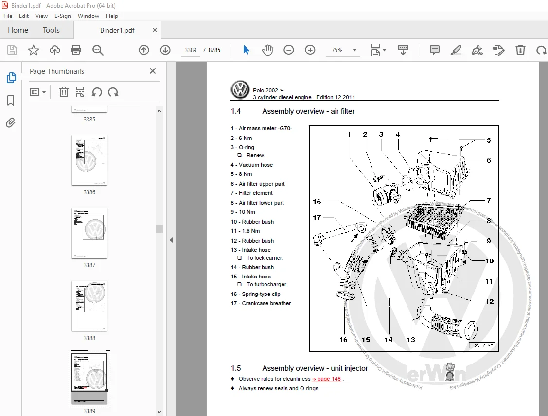
1 6 Air filter housing: dismantling and assembling 827
1 6 1 Removing 828
1 6 2 Installation 829
1 7 Safety precautions 829
1 8 Rules for cleanliness 830
1 9 Technical data 830
2 Checking components 832
2 1 Injectors: checking 832
2 1 1 Checking spray pattern and for leaks 832
2 1 2 Checking process 832
2 2 Fuel pressure regulator and holding pressure: checking 834
2 2 1 Checking process 835
2 2 2 Fuel pressure regulator: checking 837
2 2 3 Checking process 837
3 Engine control unit 839
3 1 Remove and assemble engine control unit 839
3 1 1 Removing 839
3 1 2 Installation 839
3 2 Adapting components 839
3 2 1 Work sequence 840
3 3 Interrogate engine control unit fault memory 840
3 3 1 Work sequence 841
3 3 2 Select operating mode: 841
3 3 3 Select vehicle system: 841
3 3 4 Select diagnostic function: 841
26 – Exhaust system 842
1 Exhaust system components: dismantling and fitting 842
1 1 Exhaust manifold, front exhaust pipe and catalytic converterwith attachments 842
1 2 Silencer with mountings 843
28 – Ignition system 844
1 Ignition system: repairing 844
1 1 General information: ignition system 844
1 2 Ignition system components: dismantling and fitting 844
1 3 Safety precautions 845
1 4 Test data, spark plugs 846
D3E8030C9AA 4 Cyl injection engine (2 valves roller rocker fingers) 847
00 – Technical data 851
1 Technical data 851
1 1 Engine number 851
1 2 Engine data 851
10 – Removing and installing engine 853
1 Engine: dismantling and fitting 853
1 1 Dismantling: notes 854
1 1 1 Vehicles with air conditioning 855
1 1 2 Continued for all vehicles 855
1 2 Engine: securing engine to assembly stand 856
1 2 1 Work sequence 856
1 3 Installing: notes 857
1 3 1 Vehicles with air conditioning 857
1 3 2 Continued for all vehicles 858
1 4 Tightening torques 858
1 5 Engine brackets 858
1 5 1 Tightening torques 858
1 6 Additional information and installation work on vehicles with air conditioning 859
13 – Crankshaft group 861
1 Engine: dismantling and assembling 861
1 1 Ribbed belt: dismantling and fitting 864
1 1 1 Vehicles without air conditioning compressor 864
1 1 2 Removing 864
1 1 3 Installation 864
1 1 4 Ribbed belt routing 865
1 1 5 Vehicles without air conditioning compressor 865
1 1 6 Removing 865
1 1 7 Installing ribbed belt 866
1 1 8 Ribbed belt routing 867
2 Sealing flange and engine flywheel: dismantling and fitting 868
2 1 Crankshaft oil seal -belt pulley end: renew 869
2 1 1 Removing 869
2 1 2 Installation 870
2 2 Renewing crankshaft sealing flange flywheel end: renew 871
2 2 1 Remove the sealing flange with sender wheel 872
2 2 2 Work sequence 872
2 2 3 Fit the sealing flange to the sender wheel 873
2 2 4 A-Assembling sealing flange with sender wheel on Assembly tool -T10017- 873
2 2 5 B-Assembly tool -T10017- with sealing flange on crankshaft flange 875
2 2 6 Prerequisites 875
2 2 7 Work sequence 876
2 2 8 C-Fitting Assembly tool -T10017- onto crankshaft flange 876
2 2 9 D-Pressing sender wheel onto crankshaft flange with Assembly tool -T10017- 877
2 2 10 E-Checking sender wheel installation position on crankshaft 877
2 2 11 F-Rectify sender wheel position 878
3 Crankshaft: dismantling and fitting 879
3 1 Identification conrod bearings 880
3 2 Colour markings 880
3 3 Crankshaft dimensions 880
4 Piston and conrod: dismantling and assembling 881
4 1 Piston and cylinder dimensions 883
15 – Cylinder head, Valve gear 884
1 Cylinder head: dismantling and fitting 884
1 1 Checking semi-automatic toothed belt tensioning roller check 886
1 1 1 Checking process 886
1 1 2 Vehicles with air conditioning 886
1 1 3 Continued for all vehicles 886
1 1 4 Vehicles with air conditioning 887
1 1 5 Continued for all vehicles 887
1 2 Toothed belt: removing, installing and tensioning 887
1 2 1 Removing 888
1 2 2 Vehicles with air conditioning 888
1 2 3 Continued for all vehicles 888
1 2 4 Installation 889
1 2 5 Work sequence 890
1 2 6 Vehicles with air conditioning 890
1 2 7 Continued for all vehicles 890
1 3 Cylinder head: dismantling and fitting 891
1 3 1 Prerequisites 892
1 3 2 Work sequence 892
1 3 3 Installation 894
1 4 Compression ratio: checking 895
1 4 1 Check conditions 896
1 4 2 Work sequence 896
2 Servicing valve gear: repairing 898
2 1 Rework valve seats: reworking 900
2 1 1 Calculate the max permissible reworking dimension 901
2 1 2 Example: 901
2 2 Replacing camshaft oil seal change 902
2 2 1 Removing 902
2 2 2 Installation 903
2 3 Remove and install the cylinder head cover and the cam shaft 903
2 3 1 Removing 904
2 3 2 Work sequence 904
2 3 3 Installation 905
2 4 Valve guides: checking 906
2 4 1 Checking process 907
2 5 Renewing valve stem seals: renew 907
2 5 1 Removing 908
2 5 2 Installation 909
17 – Lubrication 910
1 Lubrication system components: dismantling and fitting 910
1 1 Sump: dismantling and fitting 913
1 1 1 Work sequence 913
1 1 2 Installation 914
1 2 Oil pump dismantling and fitting 915
1 2 1 Removing 916
1 2 2 Installation 917
1 2 3 Work sequence 917
1 3 Oil pressure sender and oil pressure switch: checking 918
1 3 1 Check conditions 919
1 3 2 Checking process 919
19 – Cooling system 920
1 Cooling system components: dismantling and fitting 920
1 1 Parts of cooling system, body side 920
1 2 Cooling system components, engine side 922
1 2 1 Coolant pump side 923
1 3 Coolant hose connection diagram 924
1 4 Coolant: draining and filling cooling system 925
1 4 1 Draining 925
1 4 2 Filling 926
1 4 3 With cooling system filling -VAS 6096- 927
1 4 4 Without cooling system filling -VAS 6096- 927
1 4 5 With and without cooling system filling -VAS 6096- 927
1 5 Radiator: dismantling and fitting 927
1 5 1 Removing 928
1 5 2 Installation 928
1 5 3 Additional information and installation work on vehicles with air conditioning 929
1 6 Coolant pump: dismantling and fitting 929
1 6 1 Removing 930
1 6 2 Installation 930
20 – Fuel supply system 931
1 Fuel supply system components: dismantling and fitting 931
1 1 Fuel tank with accessory parts and fuel filter: dismantling and fitting 931
1 2 Safety precautions when working on the fuel supply system 934
1 3 Rules for cleanliness 934
1 4 Fuel delivery unit dismantling and fitting 935
1 4 1 Removing 935
1 4 2 Installation 936
1 5 Fuel gauge sender: dismantling and fitting 936
1 5 1 Removing 936
1 5 2 Installation 937
1 6 Fuel tank: dismantling and fitting 937
1 6 1 Removing 937
1 6 2 Installation 938
1 7 Crash fuel shut off 939
1 7 1 Function 939
1 8 Fuel pump: checking 939
1 8 1 Check conditions 940
1 8 2 Checking function and voltage supply 941
1 8 3 Checking delivery rate 942
1 8 4 Checking process 942
1 8 5 Checking fuel pump non-return valve 944
1 8 6 Checking process 945
2 Servicing parts of electronic power control (EPC): repairing 946
2 1 Function of EPC system 946
3 Activated charcoal filter system 948
3 1 Function 948
3 2 Servicing parts of the activated charcoal filter system: repairing 948
3 3 Fuel tank breather: checking 949
3 3 1 Test conditions 950
3 3 2 Checking process 950
24 – Mixture preparation, Injection 951
1 Injection system: repairing 951
1 1 General notes on injection 951
1 2 Fitting locations overview 951
1 3 Injection system components: dismantling and fitting 953
1 4 Intake manifold: dismantling and assembling 956
1 5 Fuel rail with injectors: dismantling and assembling 957
1 6 Air filter housing: dismantling and assembling 957
1 6 1 Removing 958
1 6 2 Installation 959
1 7 Safety precautions 959
1 8 Rules for cleanliness 960
1 9 Technical data 960
2 Checking components 962
2 1 Injectors: checking 962
2 1 1 Checking spray pattern and for leaks 962
2 1 2 Checking process 962
2 2 Fuel pressure regulator and holding pressure: checking 964
2 2 1 Checking process 965
2 2 2 Fuel pressure regulator: checking 967
2 2 3 Checking process 967
3 Engine control unit 969
3 1 Remove and assemble engine control unit 969
3 1 1 Removing 969
3 1 2 Installation 969
3 2 Adapting components 969
3 2 1 Work sequence 970
3 3 Interrogate engine control unit fault memory 970
3 3 1 Work sequence 971
3 3 2 Select operating mode: 971
3 3 3 Select vehicle system: 971
3 3 4 Select diagnostic function: 971
26 – Exhaust system 972
1 Exhaust system components: dismantling and fitting 972
1 1 Exhaust manifold, front exhaust pipe and catalytic converter with attachments 972
1 2 Silencer with mountings 973
28 – Ignition system 974
1 Ignition system: repairing 974
1 1 General information: ignition system 974
1 2 Ignition system components: dismantling and fitting 974
1 3 Safety precautions 975
1 4 Test data, spark plugs 976
D3E8033005A Electrical system South Africa 977
27 – Starter, current supply, CCS 985
1 Battery 985
1 1 Types of battery 985
1 2 Warning notices and safety regulations 985
1 3 Battery terminal connection 985
2 Checking battery 986
3 Charging battery 987
4 Disconnecting and reconnecting batteries 988
4 1 Disconnecting battery 988
4 2 Connecting battery 989
5 Removing and installing battery 992
5 1 Removing battery 992
5 2 Installing battery 992
5 3 Removing and installing battery console (vehicles as of 04 05) 993
6 Specified torques: battery 997
7 Starter 998
7 1 Checking starter -B- 998
7 2 Removing and installing starter, manual gearbox 998
7 2 1 Vehicles with 1 2 l 40 kW or 47 kW injection engine with manual gearbox 998
7 2 2 Vehicles with 1 4 l 51 kW, 55 kW or 74 kW injection engine with manual gearbox 999
7 2 3 Vehicles with a 1 4 l 59 kW injection engine and manual gearbox 1001
7 2 4 Vehicles with 1 4 l 63 kW FSI engine and manual gearbox 1002
7 2 5 Vehicles with 1 6 l 77 kW FSI engine and manual gearbox 1003
7 2 6 Vehicles with 1 8 l 110 kW turbo engine and manual gearbox 1005
7 2 7 Vehicles with 1 4 l 51 kW, 55 kW or 59 kW TDI engine and manual gearbox 1006
7 2 8 Vehicles with 1 9 l 47 kW SDI engine and manual gearbox 1008
7 2 9 Vehicles with 1 9 l 74 kW TDI engine and manual gearbox 1010
7 3 Removing and installing starter, automatic gearbox 1012
7 3 1 Vehicles with a 1 4 l injection engine (engine codes BBY, BKY, BCC) and automatic gearbox 1012
7 3 2 Vehicles with a 1 6 l 77 kW injection engine and automatic gearbox 1013
8 Specified torques: starter 1016
9 Alternator, vehicles up to 03 05 1017
9 1 Securing battery positive wire to alternator 1017
9 2 Checking poly V-belt 1017
9 3 Checking alternator -C- 1017
9 3 1 Checking alternator -C- 1017
9 4 Alternator, 1 2 l 40 kW or 47 kW injection engine 1018
9 4 1 Assembly overview 1018
9 4 2 Removing and installing alternator, 1 2 l 40 kW or 47 kW injection engine 1019
9 4 3 Routing poly-V-belt, 1 2 l 40 kW or 47 kW injection engine 1022
9 5 Alternator, 1 4 l 55 kW or 74 kW injection engine 1022
9 5 1 Assembly overview 1022
9 5 3 Removing and installing alternator, 1 4 l 55 kW or 74 kW injection engine 1024
9 5 4 Routing poly-V-belt, 1 4 l 55 kW or 74 kW injection engine 1028
9 6 Alternator, 1 4 l 63 kW FSI engine 1028
9 6 1 Assembly overview 1028
9 6 2 Removing and installing alternator, 1 4 l 63 kW FSI engine 1030
9 6 3 Routing poly V-belt, 1 4 l 63 kW FSI engine 1033
9 7 Alternator, 1 6 l 77 kW injection engine 1033
9 7 1 Assembly overview – 1 6 l 77 kW injection engine 1033
9 7 2 Removing and installing alternator, 1 6 l 77 kW injection engine 1035
9 7 3 Poly V-belt routing, 1 6 l 77 kW injection engine 1038
9 8 Alternator, 1 4 l 51 kW or 55 kW TDI engine 1038
9 8 1 Assembly overview 1038
9 8 2 Removing and installing alternator, 1 4 l 55 kW TDI engine 1040
9 8 3 Routing poly V-belt, 1 4 l 55 kW TDI engine 1042
9 9 Alternator, 1 9 l 47 kW SDI engine 1043
9 9 1 Assembly overview 1043
9 9 2 Removing and installing alternator, 1 9 l 47 kW SDI engine 1043
9 9 3 Routing poly V-belt, 1 9 l 47 kW SDI engine 1046
9 10 Alternator, 1 9 l 74 kW or 96 kW TDI engine 1047
9 10 1 Assembly overview 1047
9 10 3 Removing and installing alternator, 1 9 l 74 kW or 96 kW TDI engine 1048
9 10 4 Routing poly V-belt, 1 9 l 74 kW or 96 kW TDI engine 1051
9 11 Removing and installing poly V-belt pulley on alternator 1052
9 11 1 Removing and installing poly V-belt pulley with no freewheel 1052
9 11 2 Removing and installing poly V-belt pulley with a freewheel, manufacturer: Bosch 1053
9 11 3 Removing and installing poly V-belt pulley with a freewheel, manufacturer: Valeo 1054
9 12 Voltage regulator for alternator 1056
9 12 1 Removing and installing voltage regulator, manufacturer: Bosch 1057
9 12 2 Removing and installing voltage regulator, manufacturer: Valeo 1057
10 Alternator, vehicles as of 04 05 1060
10 1 Securing battery positive wire to alternator 1060
10 2 Checking poly V-belt 1060
10 3 Checking alternator -C- 1060
10 4 Alternator, 1 2 l 40 kW or 47 kW injection engine 1060
10 5 Alternator, 1 4 l 55 kW or 74 kW injection engine 1060
10 6 Alternator, 1 4 l 63 kW FSI engine 1060
10 7 Alternator, 1 6 l 77 kW injection engine 1060
10 7 1 Assembly overview – 1 6 l 77 kW injection engine 1060
10 7 2 Removing and installing alternator, 1 6 l 77 kW injection engine 1062
10 7 3 Poly V-belt routing, 1 6 l 77 kW injection engine 1065
10 8 Alternator, 1 8 l 110 kW turbo engine 1065
10 8 1 Assembly overview 1065
10 8 3 Removing and installing alternator, 1 8 l 110 kW turbo engine 1067
10 8 4 Routing poly-V-belt, 1 8 l 110 kW turbo engine 1071
10 9 Alternator, 1 4 l 51 kW, 55 kW or 59 kW TDI engine 1071
10 9 1 Assembly overview 1072
10 9 2 Removing and installing alternator, 1 4 l 51 kW, 55 kW or 59 kW TDI engine 1073
10 9 3 Routing poly V-belt, 1 4 l 51 kW, 55 kW or 59 kW TDI engine 1076
10 10 Alternator, 1 9 l 47 kW SDI engine 1076
10 11 Alternator, 1 9 l 74 kW or 96 kW TDI engine 1076
10 11 1 Assembly overview 1076
10 11 3 Removing and installing alternator, 1 9 l 74 kW or 96 kW TDI engine 1078
10 11 4 Routing poly V-belt, 1 9 l 74 kW or 96 kW TDI engine 1081
10 12 Removing and installing poly V-belt pulley on alternator 1082
10 13 Voltage regulator for alternator 1082
11 Alternator, vehicles as of 06 06 1083
11 1 Securing battery positive wire to alternator 1083
11 2 Checking poly V-belt 1083
11 3 Checking alternator -C- 1083
11 4 Alternator, 1 2 l 40 kW or 47 kW injection engine 1083
11 5 Alternator, 1 4 l 55 kW or 74 kW injection engine 1083
11 6 Alternator, 1 4 l 59 kW injection engine with air conditioning system 1083
11 6 1 Assembly overview 1083
11 6 3 Removing and installing alternator, 1 4 l 59 kW injection engine with air conditioning system 1085
11 6 4 Routing poly V-belt, 1 4 l TDI engine, 59 kW, with air conditioning system 1088
11 7 Alternator, 1 4 l 59 kW injection engine with air no conditioning system 1088
11 7 1 Assembly overview 1088
11 7 3 Removing and installing alternator, 1 4 l 59 kW injection engine with no air conditioning system 1089
11 7 4 Routing poly V-belt, 1 4 l 59 kW TDI engine with no air conditioning system 1093
11 8 Alternator, 1 6 l 77 kW injection engine 1093
11 9 Alternator, 1 8 l 110 kW turbo engine 1093
11 10 Alternator, 1 4 l 51 kW or 59 kW TDI engine 1093
11 11 Alternator, 1 9 l 74 kW or 96 kW TDI engine 1093
11 12 Removing and installing poly V-belt pulley on alternator 1093
11 13 Voltage regulator for alternator 1093
12 Alternator, vehicles with diesel particulate filter 1095
12 1 Securing battery positive wire to alternator 1095
12 2 Checking poly V-belt 1095
12 3 Checking alternator -C- 1095
12 4 Alternator, 1 4 l 51 kW TDI engine with air conditioning system 1095
12 4 1 Assembly overview 1095
12 4 3 Removing and installing alternator, 1 4 l 51 kW TDI engine with air conditioning system 1097
12 4 4 Routing poly V-belt, 1 4 l 51 kW TDI engine with air conditioning system, as of 2007 1100
12 5 Alternator, 1 4 l 51 kW TDI engine with no air conditioning system 1100
12 5 1 Assembly overview 1100
12 5 3 Removing and installing alternator, 1 4 l 51 kW TDI engine with no air conditioning system 1102
12 5 4 Routing poly V-belt, 1 4 l 51 kW TDI engine with no air conditioning system 1106
12 6 Alternator, 1 4 l 59 kW TDI engine with air conditioning system 1106
12 6 1 Assembly overview 1106
12 6 3 Removing and installing alternator, 1 4 l 59 kW TDI engine with air conditioning system 1107
12 6 4 Routing poly V-belt, 1 4 l 59 kW TDI engine with air conditioning system 1110
12 7 Alternator, 1 4 l 59 kW TDI engine with no air conditioning system 1111
12 7 1 Assembly overview 1111
12 7 3 Removing and installing alternator, 1 4 l 59 kW TDI engine with no air conditioning system 1112
12 7 4 Routing poly V-belt, 1 4 l 59 kW TDI engine with no air conditioning system 1116
12 8 Alternator, 1 9 l 74 kW TDI engine with air conditioning system 1116
12 8 1 Assembly overview 1116
12 8 3 Removing and installing alternator, 1 9 l 74 kW TDI engine with air conditioning system 1117
12 8 4 Routing poly V-belt, 1 9 l 74 kW TDI engine with air conditioning system 1121
12 9 Alternator, 1 9 l 74 kW TDI engine with no air conditioning system 1121
12 9 1 Assembly overview 1121
12 9 3 Removing and installing alternator, 1 9 l 74 kW TDI engine with no air conditioning system 1123
12 9 4 Routing poly V-belt, 1 9 l 74 kW TDI engine with no air conditioning system 1127
12 10 Removing and installing poly V-belt pulley on alternator 1127
12 11 Voltage regulator for alternator 1127
13 Cruise control system (CCS) 1128
13 1 Activating and deactivating cruise control system (CCS) 1128
90 – Gauges, instruments 1129
1 Dash panel insert 1129
1 1 Renewing dash panel insert 1129
1 2 Removing and installing dash panel insert 1130
1 3 Description of back of dash panel insert 1131
1 4 Warning lamp symbols in dash panel insert 1131
2 Service interval display 1133
2 1 Resetting service interval display 1133
92 – Windscreen wash/wipe system 1134
1 Windscreen wiper system 1134
1 1 Removing and installing windscreen wiper system 1134
1 1 1 Removing wiper arms 1134
1 1 2 Removing plenum chamber cover 1135
1 1 3 Removing bulkhead 1135
1 1 4 Removing wiper frame with linkage and windscreen wiper motor -V- 1136
1 1 5 Removing windscreen wiper motor -V- from wiper frame 1137
1 1 6 Installing windscreen wiper motor -V- in wiper frame 1137
1 1 7 Setting park position 1138
1 1 8 Installing wiper frame with linkage and windscreen wiper motor -V- 1138
1 1 9 Installing plenum chamber cover 1139
1 1 10 Installing wiper arms 1139
1 2 Adjusting wiper blade park position 1139
1 2 1 Vehicles ▸12 02 with windscreen wiper system 6Q1/6Q2 955 023 D and 6QE 955 023 1140
1 2 2 Vehicles 01 03 ▸ 08 03 1141
1 2 3 Vehicles 09 03 ▸ with windscreen wiper system 6Q1/6Q2 955 023 E 1141
1 3 Aerodynamic wiper 1142
1 3 2 Removing and installing wiper rubber blade on aero windscreen wiper 1142
1 4 Removing and installing rain sensor -G213- 1143
1 5 Fitting a new adhesive pad to the rain sensor (Valeo) 1144
1 5 1 Preparing windscreen 1145
1 5 2 Preparing rain sensor 1145
1 5 3 Bonding a new adhesive pad to the rain sensor 1145
1 5 4 Installing rain sensor 1147
2 Windscreen washer system 1149
2 1 Assembly overview – windscreen washer system 1149
2 2 Removing and installing reservoir for windscreen and headlight washer system 1151
2 3 Removing and installing windscreen and rear window washer pump -V59- 1152
2 4 Removing and installing windscreen washer fluid level sender -G33- 1153
2 5 Removing and installing windscreen washer jets 1154
2 6 Cleaning spray jets for front windscreen washer system 1154
2 7 Adjusting windscreen washer system washer jets 1154
3 Rear window wiper system 1155
3 1 Assembly overview – rear window wiper system 1155
3 2 Removing and installing rear window wiper 1155
3 2 1 Removing wiper arm 1155
3 2 2 Removing and installing rear window wiper motor 1156
3 3 Adjusting rear window wiper park position 1156
3 3 1 Vehicles up to 03 05 1156
3 3 2 Vehicles as of 04 05 1157
4 Rear window washer system 1158
4 1 Assembly overview – rear window washer system 1158
4 2 Removing and installing spray jet 1159
4 3 Cleaning spray jet 1159
4 4 Adjusting washer jet 1159
5 Headlight washer system 1160
5 1 Assembly overview – headlight washer system 1160
5 2 Removing and installing washer jet assembly 1162
5 3 Removing and installing pop-up washer spray jet cylinder, vehicles up to 03 05 1162
5 4 Removing and installing pop-up washer spray jet cylinder, vehicles as of 04 05 1163
5 5 Removing and installing headlight washer system pump -V11- 1164
5 6 Adjusting headlight washer system jets 1164
5 7 Bleeding headlight washer system 1164
6 Washer fluid line hose couplings 1165
7 Hose repair 1166
8 Specified torques for windscreen wash/wipe system 1167
94 – Lights, bulbs, switches – exterior 1168
1 Headlight, vehicles up to 03 05 1168
1 1 Assembly overview – headlight 1168
1 2 Removing and installing headlight 1169
1 3 Adjusting headlight installation position 1171
1 4 Renewing headlight bulbs 1172
1 4 1 Renewing side light bulb 1172
1 4 2 Renewing headlight dipped beam bulb 1174
1 4 3 Renewing headlight main beam bulb 1176
1 4 4 Renewing front turn signal bulb 1178
1 5 Headlight range control motor 1180
1 5 2 Removing and installing headlight range control motor (headlight manufacturer: Automotive Lighting) 1181
1 5 3 Removing and installing headlight range control motor (headlight manufacturer: Valeo) 1183
1 6 Repairing headlight retaining tabs 1185
1 6 1 Repairing upper retaining tab 1185
1 6 2 Repairing outer retaining tab 1186
1 7 Converting headlights for use when driving on the left or right 1187
1 7 1 Fitting conversion foil 1188
1 8 Adjusting headlight 1189
2 Headlight, vehicles as of 04 05 1190
2 1 Assembly overview – headlight 1190
2 2 Removing and installing headlight 1192
2 3 Adjusting headlight installation position 1193
2 4 Renewing headlight bulbs; headlight manufacturer: Hella 1195
2 4 1 Renewing side light bulb 1195
2 4 2 Renewing headlight dipped beam bulb 1197
2 4 3 Renewing headlight main beam bulb 1200
2 4 4 Renewing front turn signal bulb 1202
2 5 Renewing headlight bulbs; headlight manufacturer: Valeo 1204
2 5 1 Renewing side light bulb 1204
2 5 2 Renewing headlight dipped beam bulb 1205
2 5 3 Renewing headlight main beam bulb 1208
2 5 4 Renewing front turn signal bulb 1210
2 6 Headlight range control motor 1212
2 6 2 Removing and installing headlight range control motor (headlight manufacturer: Hella) 1213
2 6 3 Removing and installing headlight range control motor (headlight manufacturer: Valeo) 1216
2 7 Repairing headlight retaining tabs 1218
2 7 1 Repairing upper retaining tab 1218
2 7 2 Repairing side retaining tab 1219
2 7 3 Repairing lower retaining tab 1220
2 8 Converting headlights for use when driving on the left or right 1221
2 8 1 Converting headlights designed for driving on the right to driving on the left 1221
2 8 2 Converting headlights designed for driving on the left to driving on the right 1222
2 9 Adjusting headlight 1223
3 Front fog light, vehicles up to 03 05 1224
3 1 Fog lights (except Polo Fun) 1224
3 1 1 Removing and installing fog light 1224
3 1 2 Removing and installing left fog light bulb -L22- and right fog light bulb -L23- 1225
3 2 Fog lights (Polo Fun only) 1226
3 2 1 Removing and installing fog light 1226
3 2 2 Removing and installing left fog light bulb -L22- and right fog light bulb -L23- 1227
3 3 Adjusting fog light 1228
4 Front fog light, vehicles as of 04 05 1229
4 1 Fog lights (except Polo Cross/Dune) 1229
4 1 1 Removing and installing fog light 1229
4 1 2 Removing and installing left fog light bulb -L22- and right fog light bulb -L23- 1230
4 2 Fog light Polo Cross (Polo Dune) 1231
4 2 1 Removing and installing fog light 1231
4 2 2 Removing and installing left fog light bulb -L22- and right fog light bulb -L23- 1231
4 3 Adjusting fog light 1232
5 Side mounted repeater turn signals, vehicles up to 03 05 1233
5 1 Removing and installing side mounted repeater turn signal 1233
6 Mirror turn signal bulb in exterior mirror, vehicles from 04 05 1234
7 Tail lights, vehicles up to 03 05 1235
7 1 Assembly overview – tail lights 1235
7 2 Removing and installing tail light 1236
7 3 Removing and installing bulb holder 1237
8 Tail lights, vehicles as of 04 05 1238
8 1 Assembly overview – tail lights 1238
8 2 Removing and installing tail light 1238
8 3 Removing and installing bulb holder 1239
9 Additional brake light 1241
9 1 Additional brake light (except Polo GTI, Polo Blue Motion) 1241
9 1 1 Removing and installing additional brake light 1241
9 1 2 Removing and installing bulb holder 1242
9 2 Additional brake light (Polo GTI, Polo Blue Motion) 1242
10 Number plate lights 1244
10 1 Removing and installing number plate light -X- 1244
11 Steering column switch 1245
11 1 Removing and installing steering column switch 1246
11 2 Removing and installing airbag coil connector and return ring with slip ring -F138- 1248
11 3 Basic setting of steering angle sensor -G85- 1249
12 Ignition/starter switch and lock cylinder 1251
12 1 Removing and installing lock cylinder 1251
12 2 Ignition/starter switch -D- 1252
12 2 1 Removing and installing ignition/starter switch -D- 1253
12 2 2 Pin assignment for ignition/starter switch -D- 1253
13 Steering lock housing 1254
13 1 Removing and installing steering lock housing 1254
14 Parking aid, vehicles as of 04 05 1256
14 1 Assembly overview 1256
14 2 Parking aid control unit -J446- 1257
14 2 1 Removing and installing parking aid control unit -J446- 1257
14 2 2 Parking aid control unit -J446- final control diagnosis 1257
14 2 3 Adapting parking aid control unit -J446- 1258
14 2 4 Coding parking aid control unit -J446- 1258
14 2 5 Pin assignment of parking aid control unit -J446- 1259
14 3 Parking aid warning buzzer -H15- 1259
14 3 1 Removing and installing parking aid warning buzzer -H15- 1259
14 4 Rear parking aid senders 1259
14 4 1 Removing and installing rear parking aid sender 1259
14 4 2 Renewing bumper cover in cases of repair 1260
14 4 3 Renewing individual sender retainer in cases of repair 1260
14 4 4 Renewing individual sender in cases of repair 1261
15 Specified torques: lights, bulbs, switches – exterior 1262
15 1 Specified torques: headlight 1262
15 2 Specified torques: fog light 1262
15 3 Specified torques: tail light 1262
15 4 Specified torques: additional brake light 1262
15 5 Specified torques: steering column switch 1262
96 – Lights, bulbs, switches – interior 1263
1 Interior lights and switches 1263
1 1 Removing and installing interior monitoring deactivation switch -E267- 1263
2 Lights and switches in engine compartment 1264
2 1 Removing and installing bonnet contact switch -F266- 1264
3 Lights and switches in dash panel 1265
3 1 Removing and installing light switch -E1- 1265
3 2 Removing and installing headlight range control adjuster -E102- and switches and instruments lighting control -E20- 1266
3 3 Removing and installing switches, lights and regulators in centre of dash panel 1266
3 4 Removing and installing front passenger side airbag deactivation key switch -E224- 1268
4 Lights and switches in front doors 1269
4 1 Removing and installing switch module for driver side window lift 1269
4 2 Removing and installing window lift switch in passenger door -E107- 1269
4 3 Removing and installing switch module for driver side mirror adjustment 1270
4 4 Removing and installing driver side interior locking switch -E150- 1270
4 5 Removing and installing central locking deadlock function warning lamp -K133- 1271
4 6 Removing and installing left door warning lamp -M27- and right door warning lamp -M28- 1272
4 7 Removing and installing door contact switch 1273
5 Lights and switches in rear doors 1275
5 1 Removing and installing rear left window regulator switch in door -E52- 1275
5 2 Removing and installing rear right window regulator switch in door -E54- 1275
6 Lights and switches in luggage compartment 1276
6 1 Removing and installing luggage compartment light switch -F5- 1276
6 2 Removing and installing luggage compartment light -W3- 1276
7 Lights and switches in roof trim 1278
7 1 Front interior light -W1- 1278
7 1 1 Removing and installing front interior light -W1- 1278
7 1 2 Renewing bulb in front interior light -W1- 1279
7 2 Front interior light -W1- with reading lights and preparation for telephone 1280
7 2 1 Removing and installing front interior light -W1- 1280
7 2 2 Renewing bulb in front interior light -W- 1282
7 2 3 Renewing bulb in front passenger reading light -W13- and driver side reading light -W19- 1283
7 3 Front interior light -W1- with reading lights and regulator for sunroof 1284
7 3 1 Removing and installing front interior light -W1- 1284
7 3 2 Renewing bulb in front interior light -W1- 1285
7 3 3 Renewing bulb in front passenger reading light -W13- and driver side reading light -W19- 1286
7 3 4 Removing and installing sliding sunroof adjustment regulator -E139- 1287
7 4 Rear interior light -W43- 1288
7 4 1 Removing and installing rear interior light -W43- 1288
7 4 2 Renewing bulb in rear interior light -W43- 1289
7 5 Removing and installing illuminated vanity mirror 1289
8 Horn 1292
8 1 Single tone horn 1292
8 1 1 Removing and installing single tone horn 1292
8 1 2 Checking single tone horn 1293
8 2 Dual tone horn 1293
8 2 1 Removing and installing dual-tone horn 1293
8 2 2 Checking dual tone horn 1295
8 3 Horn plate -H- 1295
8 3 1 Removing and installing signal horn activation -H- 1295
8 3 2 Checking horn plate -H- 1296
9 Immobilizer 1297
9 1 Immobilizer control unit -J362- 1297
9 2 Immobilizer reader coil -D2- 1297
9 3 Ignition key 1297
9 3 1 Ignition key – variable code transponder 1297
9 3 2 Adapting ignition keys to the immobilizer 1298
9 3 3 Adapting ignition keys to the convenience system 1298
10 Anti-theft alarm system (ATA) 1299
10 1 Activating and deactivating anti-theft alarm system 1299
10 2 Removing and installing interior monitoring deactivation switch -E267- 1300
10 3 Anti-theft alarm ultrasonic sensor -G209- 1300
10 3 1 Removing and installing ATA ultrasonic sensor -G209- (vehicles without sliding sunroof) 1300
10 3 2 Removing and installing ATA ultrasonic sensor -G209- (vehicles with sliding sunroof) 1301
10 4 Central locking and anti-theft alarm system aerial -R47- 1302
10 5 Alarm horn -H12- 1303
10 5 1 Removing and installing alarm horn -H12- 1303
10 5 2 Removing and installing alarm horn -H12- For South Africa use 1304
10 5 3 Removing and installing alarm horn -H12- For South Africa use 1304
11 Specified torques: lights, bulbs, switches – interior 1306
11 1 Specified torques: horn or dual tone horn -H1- 1306
11 2 Specified torques: signal horn activation -H- 1306
11 3 Specified torques: alarm horn -H12- 1306
97 – Wiring 1307
1 Vehicle diagnosis, testing and information systems 1307
2 Fuse holder 1308
2 1 Removing and installing fuse holder 1308
2 2 Main fuse carrier, vehicles up to 03 05 1308
2 2 1 Removing and installing main fuse carrier (version 1) 1309
2 2 2 Removing and installing main fuse carrier (version 2) 1311
2 3 Main fuse carrier, vehicles as of 04 05 1313
2 3 1 Removing and installing main fuse carrier (version 1) 1314
2 3 2 Removing and installing main fuse carrier (version 2) 1317
3 Relay carrier 1321
3 1 Removing and installing relay carrier 1321
4 Potential distributor 1323
4 1 Removing and installing voltage distributor 1323
5 Connector points and compact connector 1324
5 1 A-pillar coupling station 1324
5 2 B-pillar coupling station 1324
5 3 Compact connector at bulkhead 1324
5 3 1 Removing/installing bulkhead connectors on engine end and releasing/locking compact connector on engine end 1325
5 3 2 Removing and installing compact connector 1326
6 Control units 1328
6 1 Onboard supply control unit -J519- 1328
6 1 1 Removing and installing onboard supply control unit -J519- 1329
6 1 2 Renewing onboard supply control unit -J519- 1330
6 1 3 Coding onboard supply control unit -J519- 1330
6 1 4 Activating “comfort signaling/blinking” 1331
6 1 5 Adapting turn signal cycles for “tap signaling” 1331
6 2 Data bus diagnostic interface -J533- 1332
6 3 Convenience system central control unit -J393- 1332
6 3 1 Removing and installing convenience system central control unit -J393- 1333
6 3 2 Coding convenience system central control unit -J393- 1333
6 3 3 Checking anti-theft alarm 1333
7 Specified torques: wires/cables 1334
7 1 Specified torques: fuse holder 1334
7 2 Specified torques: main fuse carrier 1334
7 3 Specified torques: compact connector 1334
8 Wiring harness and connector repairs 1335
D3E8033005B Electrical system 1336
27 – Starter, current supply, CCS 1344
1 Battery 1344
1 1 Types of battery 1344
1 2 Warning notices and safety regulations 1344
1 3 Battery terminal connection 1344
2 Checking battery 1345
3 Charging battery 1346
4 Disconnecting and reconnecting batteries 1347
4 1 Disconnecting battery 1347
4 2 Connecting battery 1348
5 Removing and installing battery 1351
5 1 Removing battery 1351
5 2 Installing battery 1351
5 3 Removing and installing battery console (vehicles as of 04 05) 1352
6 Specified torques: battery 1356
7 Starter 1357
7 1 Checking starter -B- 1357
7 2 Removing and installing starter, manual gearbox 1357
7 2 1 Vehicles with 1 2 l 40 kW or 47 kW injection engine with manual gearbox 1357
7 2 2 Vehicles with 1 4 l 51 kW, 55 kW or 74 kW injection engine with manual gearbox 1358
7 2 3 Vehicles with a 1 4 l 59 kW injection engine and manual gearbox 1360
7 2 4 Vehicles with 1 4 l 63 kW FSI engine and manual gearbox 1361
7 2 5 Vehicles with 1 6 l 77 kW FSI engine and manual gearbox 1362
7 2 6 Vehicles with 1 8 l 110 kW turbo engine and manual gearbox 1364
7 2 7 Vehicles with 1 4 l 51 kW, 55 kW or 59 kW TDI engine and manual gearbox 1365
7 2 8 Vehicles with 1 9 l 47 kW SDI engine and manual gearbox 1367
7 2 9 Vehicles with 1 9 l 74 kW TDI engine and manual gearbox 1369
7 3 Removing and installing starter, automatic gearbox 1371
7 3 1 Vehicles with a 1 4 l injection engine (engine codes BBY, BKY, BCC) and automatic gearbox 1371
7 3 2 Vehicles with a 1 6 l 77 kW injection engine and automatic gearbox 1372
8 Specified torques: starter 1375
9 Alternator, vehicles up to 03 05 1376
9 1 Securing battery positive wire to alternator 1376
9 2 Checking poly V-belt 1376
9 3 Checking alternator -C- 1376
9 3 1 Checking alternator -C- 1376
9 4 Alternator, 1 2 l 40 kW or 47 kW injection engine 1377
9 4 1 Assembly overview 1377
9 4 2 Removing and installing alternator, 1 2 l 40 kW or 47 kW injection engine 1378
9 4 3 Routing poly-V-belt, 1 2 l 40 kW or 47 kW injection engine 1381
9 5 Alternator, 1 4 l 55 kW or 74 kW injection engine 1381
9 5 1 Assembly overview 1381
9 5 3 Removing and installing alternator, 1 4 l 55 kW or 74 kW injection engine 1383
9 5 4 Routing poly-V-belt, 1 4 l 55 kW or 74 kW injection engine 1387
9 6 Alternator, 1 4 l 63 kW FSI engine 1387
9 6 1 Assembly overview 1387
9 6 2 Removing and installing alternator, 1 4 l 63 kW FSI engine 1389
9 6 3 Routing poly V-belt, 1 4 l 63 kW FSI engine 1392
9 7 Alternator, 1 6 l 77 kW injection engine 1392
9 7 1 Assembly overview – 1 6 l 77 kW injection engine 1392
9 7 2 Removing and installing alternator, 1 6 l 77 kW injection engine 1394
9 7 3 Poly V-belt routing, 1 6 l 77 kW injection engine 1397
9 8 Alternator, 1 4 l 51 kW or 55 kW TDI engine 1397
9 8 1 Assembly overview 1397
9 8 2 Removing and installing alternator, 1 4 l 55 kW TDI engine 1399
9 8 3 Routing poly V-belt, 1 4 l 55 kW TDI engine 1401
9 9 Alternator, 1 9 l 47 kW SDI engine 1402
9 9 1 Assembly overview 1402
9 9 2 Removing and installing alternator, 1 9 l 47 kW SDI engine 1402
9 9 3 Routing poly V-belt, 1 9 l 47 kW SDI engine 1405
9 10 Alternator, 1 9 l 74 kW or 96 kW TDI engine 1406
9 10 1 Assembly overview 1406
9 10 3 Removing and installing alternator, 1 9 l 74 kW or 96 kW TDI engine 1407
9 10 4 Routing poly V-belt, 1 9 l 74 kW or 96 kW TDI engine 1410
9 11 Removing and installing poly V-belt pulley on alternator 1411
9 11 1 Removing and installing poly V-belt pulley with no freewheel 1411
9 11 2 Removing and installing poly V-belt pulley with a freewheel, manufacturer: Bosch 1412
9 11 3 Removing and installing poly V-belt pulley with a freewheel, manufacturer: Valeo 1413
9 12 Voltage regulator for alternator 1415
9 12 1 Removing and installing voltage regulator, manufacturer: Bosch 1416
9 12 2 Removing and installing voltage regulator, manufacturer: Valeo 1416
10 Alternator, vehicles as of 04 05 1419
10 1 Securing battery positive wire to alternator 1419
10 2 Checking poly V-belt 1419
10 3 Checking alternator -C- 1419
10 4 Alternator, 1 2 l 40 kW or 47 kW injection engine 1419
10 5 Alternator, 1 4 l 55 kW or 74 kW injection engine 1419
10 6 Alternator, 1 4 l 63 kW FSI engine 1419
10 7 Alternator, 1 6 l 77 kW injection engine 1419
10 7 1 Assembly overview – 1 6 l 77 kW injection engine 1419
10 7 2 Removing and installing alternator, 1 6 l 77 kW injection engine 1421
10 7 3 Poly V-belt routing, 1 6 l 77 kW injection engine 1424
10 8 Alternator, 1 8 l 110 kW turbo engine 1424
10 8 1 Assembly overview 1424
10 8 3 Removing and installing alternator, 1 8 l 110 kW turbo engine 1426
10 8 4 Routing poly-V-belt, 1 8 l 110 kW turbo engine 1430
10 9 Alternator, 1 4 l 51 kW, 55 kW or 59 kW TDI engine 1430
10 9 1 Assembly overview 1431
10 9 2 Removing and installing alternator, 1 4 l 51 kW, 55 kW or 59 kW TDI engine 1432
10 9 3 Routing poly V-belt, 1 4 l 51 kW, 55 kW or 59 kW TDI engine 1435
10 10 Alternator, 1 9 l 47 kW SDI engine 1435
10 11 Alternator, 1 9 l 74 kW or 96 kW TDI engine 1435
10 11 1 Assembly overview 1435
10 11 3 Removing and installing alternator, 1 9 l 74 kW or 96 kW TDI engine 1437
10 11 4 Routing poly V-belt, 1 9 l 74 kW or 96 kW TDI engine 1440
10 12 Removing and installing poly V-belt pulley on alternator 1441
10 13 Voltage regulator for alternator 1441
11 Alternator, vehicles as of 06 06 1442
11 1 Securing battery positive wire to alternator 1442
11 2 Checking poly V-belt 1442
11 3 Checking alternator -C- 1442
11 4 Alternator, 1 2 l 40 kW or 47 kW injection engine 1442
11 5 Alternator, 1 4 l 55 kW or 74 kW injection engine 1442
11 6 Alternator, 1 4 l 59 kW injection engine with air conditioning system 1442
11 6 1 Assembly overview 1442
11 6 3 Removing and installing alternator, 1 4 l 59 kW injection engine with air conditioning system 1444
11 6 4 Routing poly V-belt, 1 4 l TDI engine, 59 kW, with air conditioning system 1447
11 7 Alternator, 1 4 l 59 kW injection engine with air no conditioning system 1447
11 7 1 Assembly overview 1447
11 7 3 Removing and installing alternator, 1 4 l 59 kW injection engine with no air conditioning system 1448
11 7 4 Routing poly V-belt, 1 4 l 59 kW TDI engine with no air conditioning system 1452
11 8 Alternator, 1 6 l 77 kW injection engine 1452
11 9 Alternator, 1 8 l 110 kW turbo engine 1452
11 10 Alternator, 1 4 l 51 kW or 59 kW TDI engine 1452
11 11 Alternator, 1 9 l 74 kW or 96 kW TDI engine 1452
11 12 Removing and installing poly V-belt pulley on alternator 1452
11 13 Voltage regulator for alternator 1452
12 Alternator, vehicles with diesel particulate filter 1454
12 1 Securing battery positive wire to alternator 1454
12 2 Checking poly V-belt 1454
12 3 Checking alternator -C- 1454
12 4 Alternator, 1 4 l 51 kW TDI engine with air conditioning system 1454
12 4 1 Assembly overview 1454
12 4 3 Removing and installing alternator, 1 4 l 51 kW TDI engine with air conditioning system 1456
12 4 4 Routing poly V-belt, 1 4 l 51 kW TDI engine with air conditioning system, as of 2007 1459
12 5 Alternator, 1 4 l 51 kW TDI engine with no air conditioning system 1459
12 5 1 Assembly overview 1459
12 5 3 Removing and installing alternator, 1 4 l 51 kW TDI engine with no air conditioning system 1461
12 5 4 Routing poly V-belt, 1 4 l 51 kW TDI engine with no air conditioning system 1465
12 6 Alternator, 1 4 l 59 kW TDI engine with air conditioning system 1465
12 6 1 Assembly overview 1465
12 6 3 Removing and installing alternator, 1 4 l 59 kW TDI engine with air conditioning system 1466
12 6 4 Routing poly V-belt, 1 4 l 59 kW TDI engine with air conditioning system 1469
12 7 Alternator, 1 4 l 59 kW TDI engine with no air conditioning system 1470
12 7 1 Assembly overview 1470
12 7 3 Removing and installing alternator, 1 4 l 59 kW TDI engine with no air conditioning system 1471
12 7 4 Routing poly V-belt, 1 4 l 59 kW TDI engine with no air conditioning system 1475
12 8 Alternator, 1 9 l 74 kW TDI engine with air conditioning system 1475
12 8 1 Assembly overview 1475
12 8 3 Removing and installing alternator, 1 9 l 74 kW TDI engine with air conditioning system 1476
12 8 4 Routing poly V-belt, 1 9 l 74 kW TDI engine with air conditioning system 1480
12 9 Alternator, 1 9 l 74 kW TDI engine with no air conditioning system 1480
12 9 1 Assembly overview 1480
12 9 3 Removing and installing alternator, 1 9 l 74 kW TDI engine with no air conditioning system 1482
12 9 4 Routing poly V-belt, 1 9 l 74 kW TDI engine with no air conditioning system 1486
12 10 Removing and installing poly V-belt pulley on alternator 1486
12 11 Voltage regulator for alternator 1486
13 Cruise control system (CCS) 1487
13 1 Activating and deactivating cruise control system (CCS) 1487
90 – Gauges, instruments 1488
1 Dash panel insert 1488
1 1 Renewing dash panel insert 1488
1 2 Removing and installing dash panel insert 1489
1 3 Description of back of dash panel insert 1490
1 4 Warning lamp symbols in dash panel insert 1490
2 Service interval display 1492
2 1 Resetting service interval display 1492
92 – Windscreen wash/wipe system 1493
1 Windscreen wiper system 1493
1 1 Removing and installing windscreen wiper system 1493
1 1 1 Removing wiper arms 1493
1 1 2 Removing plenum chamber cover 1494
1 1 3 Removing bulkhead 1494
1 1 4 Removing wiper frame with linkage and windscreen wiper motor -V- 1495
1 1 5 Removing windscreen wiper motor -V- from wiper frame 1496
1 1 6 Installing windscreen wiper motor -V- in wiper frame 1496
1 1 7 Setting park position 1497
1 1 8 Installing wiper frame with linkage and windscreen wiper motor -V- 1497
1 1 9 Installing plenum chamber cover 1498
1 1 10 Installing wiper arms 1498
1 2 Adjusting wiper blade park position 1498
1 2 1 Vehicles ▸12 02 with windscreen wiper system 6Q1/6Q2 955 023 D and 6QE 955 023 1499
1 2 2 Vehicles 01 03 ▸ 08 03 1500
1 2 3 Vehicles 09 03 ▸ with windscreen wiper system 6Q1/6Q2 955 023 E 1500
1 3 Aerodynamic wiper 1501
1 3 2 Removing and installing wiper rubber blade on aero windscreen wiper 1501
1 4 Removing and installing rain sensor -G213- 1502
1 5 Fitting a new adhesive pad to the rain sensor (Valeo) 1503
1 5 1 Preparing windscreen 1504
1 5 2 Preparing rain sensor 1504
1 5 3 Bonding a new adhesive pad to the rain sensor 1504
1 5 4 Installing rain sensor 1506
2 Windscreen washer system 1508
2 1 Assembly overview – windscreen washer system 1508
2 2 Removing and installing reservoir for windscreen and headlight washer system 1510
2 3 Removing and installing windscreen and rear window washer pump -V59- 1511
2 4 Removing and installing windscreen washer fluid level sender -G33- 1512
2 5 Removing and installing windscreen washer jets 1513
2 6 Cleaning spray jets for front windscreen washer system 1513
2 7 Adjusting windscreen washer system washer jets 1513
3 Headlight washer system 1514
3 1 Assembly overview – headlight washer system 1514
3 2 Removing and installing washer jet assembly 1516
3 3 Removing and installing pop-up washer spray jet cylinder, vehicles up to 03 05 1516
3 4 Removing and installing pop-up washer spray jet cylinder, vehicles as of 04 05 1517
3 5 Removing and installing headlight washer system pump -V11- 1518
3 6 Adjusting headlight washer system jets 1518
3 7 Bleeding headlight washer system 1518
4 Washer fluid line hose couplings 1519
5 Hose repair 1520
6 Specified torques for windscreen wash/wipe system 1521
94 – Lights, bulbs, switches – exterior 1522
1 Headlight, vehicles up to 03 05 1522
1 1 Assembly overview – headlight 1522
1 2 Removing and installing headlight 1523
1 3 Adjusting headlight installation position 1525
1 4 Renewing headlight bulbs 1526
1 4 1 Renewing side light bulb 1526
1 4 2 Renewing headlight dipped beam bulb 1528
1 4 3 Renewing headlight main beam bulb 1530
1 4 4 Renewing front turn signal bulb 1532
1 5 Headlight range control motor 1535
1 5 2 Removing and installing headlight range control motor (headlight manufacturer: Automotive Lighting) 1535
1 5 3 Removing and installing headlight range control motor (headlight manufacturer: Valeo) 1538
1 6 Repairing headlight retaining tabs 1540
1 6 1 Repairing upper retaining tab 1540
1 6 2 Repairing outer retaining tab 1541
1 7 Converting headlights for use when driving on the left or right 1542
1 7 1 Fitting conversion foil 1543
1 8 Adjusting headlight 1544
2 Headlight, vehicles as of 04 05 1545
2 1 Assembly overview – headlight 1545
2 2 Removing and installing headlight 1547
2 3 Adjusting headlight installation position 1548
2 4 Renewing headlight bulbs; headlight manufacturer: Hella 1550
2 4 1 Renewing side light bulb 1550
2 4 2 Renewing headlight dipped beam bulb 1552
2 4 3 Renewing headlight main beam bulb 1555
2 4 4 Renewing front turn signal bulb 1557
2 5 Renewing headlight bulbs; headlight manufacturer: Valeo 1559
2 5 1 Renewing side light bulb 1559
2 5 2 Renewing headlight dipped beam bulb 1561
2 5 3 Renewing headlight main beam bulb 1564
2 5 4 Renewing front turn signal bulb 1566
2 6 Headlight range control motor 1568
2 6 2 Removing and installing headlight range control motor (headlight manufacturer: Hella) 1569
2 6 3 Removing and installing headlight range control motor (headlight manufacturer: Valeo) 1572
2 7 Repairing headlight retaining tabs 1574
2 7 1 Repairing upper retaining tab 1574
2 7 2 Repairing side retaining tab 1575
2 7 3 Repairing lower retaining tab 1576
2 8 Converting headlights for use when driving on the left or right 1577
2 8 1 Converting headlights designed for driving on the right to driving on the left 1577
2 8 2 Converting headlights designed for driving on the left to driving on the right 1578
2 9 Adjusting headlight 1579
3 Front fog light, vehicles up to 03 05 1580
3 1 Fog lights (except Polo Fun) 1580
3 1 1 Removing and installing fog light 1580
3 1 2 Removing and installing left fog light bulb -L22- and right fog light bulb -L23- 1581
3 2 Fog lights (Polo Fun only) 1582
3 2 1 Removing and installing fog light 1582
3 2 2 Removing and installing left fog light bulb -L22- and right fog light bulb -L23- 1583
3 3 Adjusting fog light 1584
4 Front fog light, vehicles as of 04 05 1585
4 1 Fog lights (except Polo Cross/Dune) 1585
4 1 1 Removing and installing fog light 1585
4 1 2 Removing and installing left fog light bulb -L22- and right fog light bulb -L23- 1586
4 2 Fog light Polo Cross (Polo Dune) 1587
4 2 1 Removing and installing fog light 1587
4 2 2 Removing and installing left fog light bulb -L22- and right fog light bulb -L23- 1587
4 3 Adjusting fog light 1588
5 Side mounted repeater turn signals, vehicles up to 03 05 1589
5 1 Removing and installing side mounted repeater turn signal 1589
6 Mirror turn signal bulb in exterior mirror, vehicles from 04 05 1590
7 Tail lights, vehicles up to 03 05 1591
7 1 Assembly overview – tail lights 1591
7 2 Removing and installing tail light 1592
7 3 Removing and installing bulb holder 1592
8 Tail lights, vehicles as of 04 05 1594
8 1 Assembly overview – tail lights 1594
8 2 Removing and installing tail light 1595
8 3 Removing and installing bulb holder 1596
9 Additional brake light 1597
9 1 Additional brake light (except Polo GTI, Polo Blue Motion) 1597
9 1 1 Removing and installing additional brake light 1597
9 1 2 Removing and installing bulb holder 1598
9 2 Additional brake light (Polo GTI, Polo Blue Motion) 1598
10 Number plate lights 1600
10 1 Removing and installing number plate light -X- 1600
11 Steering column switch 1601
11 1 Removing and installing steering column switch 1602
11 2 Removing and installing airbag coil connector and return ring with slip ring -F138- 1604
11 3 Basic setting of steering angle sensor -G85- 1605
12 Ignition/starter switch and lock cylinder 1607
12 1 Removing and installing lock cylinder 1607
12 2 Ignition/starter switch -D- 1608
12 2 1 Removing and installing ignition/starter switch -D- 1609
12 2 2 Pin assignment for ignition/starter switch -D- 1609
13 Steering lock housing 1610
13 1 Removing and installing steering lock housing 1610
14 Specified torques: lights, bulbs, switches – exterior 1612
14 1 Specified torques: headlight 1612
14 2 Specified torques: fog light 1612
14 3 Specified torques: tail light 1612
14 4 Specified torques: additional brake light 1612
14 5 Specified torques: steering column switch 1612
96 – Lights, bulbs, switches – interior 1613
1 Interior lights and switches 1613
1 1 Removing and installing interior monitoring deactivation switch -E267- 1613
2 Lights and switches in engine compartment 1614
2 1 Removing and installing bonnet contact switch -F266- 1614
3 Lights and switches in dash panel 1615
3 1 Removing and installing light switch -E1- 1615
3 2 Removing and installing headlight range control adjuster -E102- and switches and instruments lighting control -E20- 1616
3 3 Removing and installing switches, lights and regulators in centre of dash panel 1616
3 4 Removing and installing front passenger side airbag deactivation key switch -E224- 1618
4 Lights and switches in front doors 1619
4 1 Removing and installing switch module for driver side window lift 1619
4 2 Removing and installing window lift switch in passenger door -E107- 1619
4 3 Removing and installing switch module for driver side mirror adjustment 1620
4 4 Removing and installing driver side interior locking switch -E150- 1620
4 5 Removing and installing central locking deadlock function warning lamp -K133- 1621
4 6 Removing and installing left door warning lamp -M27- and right door warning lamp -M28- 1622
4 7 Removing and installing door contact switch 1623
5 Lights and switches in rear doors 1625
5 1 Removing and installing rear left window regulator switch in door -E52- 1625
5 2 Removing and installing rear right window regulator switch in door -E54- 1625
6 Lights and switches in luggage compartment 1626
6 1 Removing and installing luggage compartment light switch -F5- 1626
6 2 Removing and installing luggage compartment light -W3- 1626
7 Lights and switches in roof trim 1628
7 1 Front interior light -W1- 1628
7 1 1 Removing and installing front interior light -W1- 1628
7 1 2 Renewing bulb in front interior light -W1- 1629
7 2 Front interior light -W1- with reading lights and preparation for telephone 1630
7 2 1 Removing and installing front interior light -W1- 1630
7 2 2 Renewing bulb in front interior light -W- 1632
7 2 3 Renewing bulb in front passenger reading light -W13- and driver side reading light -W19- 1633
7 3 Front interior light -W1- with reading lights and regulator for sunroof 1634
7 3 1 Removing and installing front interior light -W1- 1634
7 3 2 Renewing bulb in front interior light -W1- 1635
7 3 3 Renewing bulb in front passenger reading light -W13- and driver side reading light -W19- 1636
7 3 4 Removing and installing sliding sunroof adjustment regulator -E139- 1637
7 4 Rear interior light -W43- 1638
7 4 1 Removing and installing rear interior light -W43- 1638
7 4 2 Renewing bulb in rear interior light -W43- 1639
7 5 Removing and installing illuminated vanity mirror 1639
8 Horn 1642
8 1 Single tone horn 1642
8 1 1 Removing and installing single tone horn 1642
8 1 2 Checking single tone horn 1643
8 2 Dual tone horn 1643
8 2 1 Removing and installing dual-tone horn 1643
8 2 2 Checking dual tone horn 1645
8 3 Horn plate -H- 1645
8 3 1 Removing and installing signal horn activation -H- 1645
8 3 2 Checking horn plate -H- 1646
9 Immobilizer 1647
9 1 Immobilizer control unit -J362- 1647
9 2 Immobilizer reader coil -D2- 1647
9 3 Ignition key 1647
9 3 1 Ignition key – variable code transponder 1647
9 3 2 Adapting ignition keys to the immobilizer 1648
9 3 3 Adapting ignition keys to the convenience system 1648
10 Anti-theft alarm system (ATA) 1649
10 1 Activating and deactivating anti-theft alarm system 1649
10 2 Removing and installing interior monitoring deactivation switch -E267- 1650
10 3 Anti-theft alarm ultrasonic sensor -G209- 1650
10 3 1 Removing and installing ATA ultrasonic sensor -G209- (vehicles without sliding sunroof) 1650
10 3 2 Removing and installing ATA ultrasonic sensor -G209- (vehicles with sliding sunroof) 1651
10 4 Central locking and anti-theft alarm system aerial -R47- 1652
10 5 Alarm horn -H12- 1653
10 5 1 Removing and installing alarm horn -H12- 1653
10 5 2 Removing and installing alarm horn -H12- For South Africa use 1654
10 5 3 Removing and installing alarm horn -H12- For South Africa use 1654
11 Specified torques: lights, bulbs, switches – interior 1656
11 1 Specified torques: horn or dual tone horn -H1- 1656
11 2 Specified torques: signal horn activation -H- 1656
11 3 Specified torques: alarm horn -H12- 1656
97 – Wiring 1657
1 Vehicle diagnosis, testing and information systems 1657
2 Fuse holder 1658
2 1 Removing and installing fuse holder 1658
2 2 Main fuse carrier, vehicles up to 03 05 1658
2 2 1 Removing and installing main fuse carrier (version 1) 1659
2 2 2 Removing and installing main fuse carrier (version 2) 1661
2 3 Main fuse carrier, vehicles as of 04 05 1663
2 3 1 Removing and installing main fuse carrier (version 1) 1664
2 3 2 Removing and installing main fuse carrier (version 2) 1667
3 Relay carrier 1671
3 1 Removing and installing relay carrier 1671
4 Potential distributor 1673
4 1 Removing and installing voltage distributor 1673
5 Connector points and compact connector 1674
5 1 A-pillar coupling station 1674
5 2 B-pillar coupling station 1674
5 3 Compact connector at bulkhead 1674
5 3 1 Removing/installing bulkhead connectors on engine end and releasing/locking compact connector on engine end 1675
5 3 2 Removing and installing compact connector 1676
6 Control units 1678
6 1 Onboard supply control unit -J519- 1678
6 1 1 Removing and installing onboard supply control unit -J519- 1679
6 1 2 Renewing onboard supply control unit -J519- 1680
6 1 3 Coding onboard supply control unit -J519- 1680
6 1 4 Activating “comfort signaling/blinking” 1681
6 1 5 Adapting turn signal cycles for “tap signaling” 1681
6 2 Data bus diagnostic interface -J533- 1682
6 3 Convenience system central control unit -J393- 1682
6 3 1 Removing and installing convenience system central control unit -J393- 1683
6 3 2 Coding convenience system central control unit -J393- 1683
6 3 3 Checking anti-theft alarm 1683
7 Specified torques: wires/cables 1684
7 1 Specified torques: fuse holder 1684
7 2 Specified torques: main fuse carrier 1684
7 3 Specified torques: compact connector 1684
8 Wiring harness and connector repairs 1685
D3E80314548 4 cyl injection engine with timing chain 1686
00 – Technical data 1692
1 Technical data 1692
1 1 Engine number 1692
1 2 Engine data 1692
10 – Removing and installing engine 1693
1 Removing and installing engine 1693
1 1 Removing 1694
1 2 Installing 1696
1 3 Torque settings 1698
1 4 Additional notes and assembly work for vehicles with air conditioner 1699
13 – Crankshaft group 1701
1 Dismantling and assembling engine 1701
1 1 Assembly overview – parts l and ll 1701
1 2 Part I Assembly overview – belt drive 1703
1 3 Part II: Assembly overview – chain drive system 1704
1 4 Removing and installing poly V-belt 1706
1 4 1 Poly V-belt routing 1707
1 5 Removing and installing valve timing housing 1707
2 Cylinder block, sealing flange 1711
2 1 Assembly overview 1711
2 2 Renewing crankshaft oil seal – belt pulley end 1713
2 3 Poly V-belt pulley securing bolt tightening procedure 1714
2 4 Characteristics of the sealing flange and the assembly device -T10017- and -T10134- 1717
2 5 Renewing crankshaft sealing flange – flywheel end (assembly tool -T10134-) 1718
2 5 1 Pressing sealing flange with sender wheel off crankshaft 1719
2 5 2 Pressing sealing flange with sender wheel onto crankshaft 1720
2 5 3 A – Assembling sealing flange with sender wheel on assembly appliance -T10134- 1721
2 5 4 B – Attaching assembling tool -T10134- with sealing flange to crankshaft flange 1722
2 5 5 C – Bolting assembly tool -T10134- onto crankshaft flange 1723
2 5 6 D – Pressing sender wheel onto crankshaft flange using assembly tool -T10134- 1724
2 5 7 E – Checking sender wheel installation position on crankshaft 1724
2 5 8 F – Re-pressing sender wheel 1725
2 6 Renewing crankshaft sealing flange – flywheel end (assembly tool -T10017-) 1726
2 6 1 Pressing sealing flange with sender wheel off crankshaft 1727
2 6 2 Pressing sealing flange with sender wheel onto crankshaft 1728
2 6 3 A-Assembling sealing flange with sender wheel on assembly appliance -T10017- 1728
2 6 4 B-Assembling appliance -T10017- with sealing flange on crankshaft flange 1730
2 6 5 C-Fitting assembly appliance -T10017- onto crankshaft flange 1731
2 6 6 D-Pressing sender wheel onto crankshaft flange with assembly appliance -T10017- 1732
2 6 7 E – Checking sender wheel installation position on crankshaft 1732
2 6 8 F – Pressing sender wheel 1733
2 7 Crankshaft dimensions 1733
3 Pistons and conrods 1735
3 1 Assembly overview 1735
3 2 Checking piston 1736
3 3 Checking cylinder bores 1737
3 4 Piston and cylinder dimensions 1737
15 – Cylinder head, valve gear 1738
1 Cylinder head 1738
1 1 Assembly overview 1738
1 2 Checking valve timing 1741
1 3 Adjusting valve timing 1742
1 4 Removing and installing timing chain and chain drive for oil pump 1746
1 5 Removing and installing camshaft housing 1754
1 6 Removing and installing cylinder head 1758
1 7 Checking compression 1761
2 Valve gear 1763
2 1 Assembly overview 1763
2 2 Checking camshaft axial clearance 1765
2 3 Reworking valve seats 1765
2 4 Checking valve guides 1767
2 5 Renewing valve stem seals 1767
17 – Lubrication 1770
1 Parts of lubrication system 1770
1 1 Engine oil 1770
1 2 Assembly overview 1770
1 3 Removing and installing sump 1773
1 4 Removing and installing oil pump 1774
1 5 Checking oil pressure and oil pressure switch 1776
19 – Cooling 1779
1 Parts of cooling system 1779
1 1 Assembly overview – parts of cooling system, body side 1779
1 2 Assembly overview – parts of cooling system, engine side 1781
1 3 Coolant hose schematic diagram 1783
1 4 Draining and filling coolant 1784
1 5 Removing and installing radiator 1786
1 6 Removing and installing coolant pump 1787
20 – Fuel supply system 1790
1 Parts of fuel supply system 1790
1 1 Assembly overview – fuel tank with attachments 1790
1 2 Safety precautions when working on fuel supply system 1793
1 3 Rules for cleanliness 1793
1 4 Removing and installing fuel delivery unit 1793
1 5 Removing and installing fuel gauge sender G 1795
1 6 Removing and installing fuel tank 1796
1 7 Assembly overview – fuel filter with attachments 1798
1 8 Removing and installing fuel filter 1799
1 9 Crash fuel shut-off 1800
1 10 Checking fuel pump 1800
1 11 Bleeding fuel system 1805
2 Electronic power control (EPC) 1808
2 1 Assembly overview 1808
3 Activated charcoal filter system 1809
3 1 Assembly overview 1809
3 2 Checking fuel tank breather 1810
24 – Mixture preparation – injection 1811
1 Injection system 1811
1 1 General notes on injection 1811
1 2 Assembly overview – intake manifold 1811
1 3 Assembly overview – fuel rail with injectors 1813
1 4 Removing and installing injectors 1813
1 5 Assembly overview – air filter 1814
1 6 Removing and installing air filter housing 1816
1 7 Cleaning throttle valve module -J338- 1817
1 8 Safety precautions 1818
1 9 Rules for cleanliness 1819
1 10 Technical data 1819
2 Checking components 1820
2 1 Checking injectors for leaks and quantity injected 1820
2 1 1 Checking for leaks 1820
2 1 2 Checking quantity injected 1821
2 2 Checking fuel pressure regulator and holding pressure 1822
3 Engine control unit -J623- 1825
3 1 Removing and installing engine control unit -J623- 1825
3 2 Vehicles with anti-theft secured engine control unit -J623- 1825
26 – Exhaust system 1827
1 Parts of the exhaust system 1827
1 1 Assembly overview – catalytic converters and attachments 1827
1 2 Assembly overview – silencers with mountings 1829
28 – Ignition system 1830
1 Ignition system 1830
1 1 Assembly overview – ignition system 1830
1 2 Removing and installing ignition coils with output stage 1831
1 3 Safety precautions 1832
1 4 Spark plug test data 1833
D4B807E3B5B Body Repairs General Body Repairs 1834
1 Safety instructions 1838
1 1 Part removal 1838
1 2 Battery and welding operation 1838
1 3 Electronic control unit 1838
1 3 1 Processing of the electronic control unit after repair dueto a traffic accident 1838
1 4 Paint, glass, soft pad and trim 1839
1 5 Fuel tank or fuel delivery pipeline 1839
1 6 Air conditioner 1839
1 6 1 Remedial measures: 1839
1 7 Airbag System 1840
1 8 Check the seat belts 1840
1 8 1 Belt body 1841
1 8 2 Automatic retractor (locking function) 1841
1 8 3 Visual inspection of the seat belt buckle 1842
1 8 4 Seat belt buckle function 1842
1 8 5 Seat belt guide member and tongue 1843
1 8 6 Fixing piece and fixing point 1843
1 9 Safety specifications for the seat belt tensioner 1843
1 10 Body repair on a vehicle equipped with the seat belt tensioners 1844
1 10 1 The following vehicles have been equipped with: 1844
1 11 Perform cutting off, correcting and/or leveling on a vehicleequipped with airbags 1845
1 12 Remove the front seats with a side airbag 1845
2 Basic instruction 1846
2 1 Diagnosis of the accident vehicle 1846
2 2 Condition of the body and/or the parts for delivery to thepainting workshop 1846
2 3 Correction 1846
2 4 Cutting 1846
2 5 Body-cut part and part section 1846
2 6 Original connection 1847
2 7 Galvanized body parts 1847
2 8 Remove the rest part 1847
2 9 New parts 1847
2 10 Parts 1847
2 11 Molded foam plastic pads 1848
3 Symbolic interpretation 1849
3 1 Symbolic interpretation for welding 1849
3 2 Symbolic interpretation for the operation method 1849
3 2 1 Grinding 1850
3 2 2 Thinning 1850
3 2 3 Punching 1850
3 2 4 Drilling 1851
3 2 5 Polishing 1851
3 2 6 Cavity corrosion protection 1851
3 2 7 Bonding 1852
3 2 8 Precise sealing 1852
4 Body repair tools 1853
4 1 Flaring tool -V A G 1317- 1853
4 2 Punching pliers -V A G 1329- 1853
4 3 Basic equipment -V A G 1366/3- 1853
4 4 Bottom protection layer spray gun -V A G 1379- 1854
4 5 Electric blower -V A G 1416- 1854
4 6 Door tensioner -V A G 1438- 1854
4 7 Body equipment component -V A G 1439- 1855
4 8 Pneumatic cutting knife -V A G 1523 A- 1855
4 9 Air chisel -V A G 1577- 1855
4 10 Edge closing iron block -V A G 1585- 1856
4 11 Welding fume ventilator -V A G 1586- 1856
4 12 Welding spot releasing device -V A G 1731- 1856
4 13 Pneumatic spray gun -V A G 1761/1- 1857
4 14 Pneumatic punching and thinning pliers -VAS 1996- 1857
4 15 Pneumatic adhesive spray gun -V A G 2005- 1857
4 16 Door hinge correction tool 1858
4 17 Hose kit 5023 for the inert gas protection welding 1858
4 18 Angle grinder -VAS 5174- 1858
4 19 Angle grinder -VAS 5175- 1859
4 20 Wire brush -VAS 5182- 1859
5 Body bonding 1860
5 1 Transporter 1991 → 1860
5 1 1 Separation process: 1860
5 1 2 Bonding process: 1860
5 2 Bonding types 1860
5 2 1 Bonding-strong 1860
5 2 2 Bonding-spot welding 1861
5 3 Repair method for replacing the parts 1861
5 3 1 Spot welding and bonding 1861
5 3 2 Plug welding and bonding (if spot welding is impossible) 1861
5 3 3 Welding fume ventilator 1862
5 3 4 Preparations 1862
5 3 5 Trimming 1862
6 Corrosion protection measures 1863
6 1 Corrosion protection 1863
7 Waste disposal instructions 1864
7 1 Waste disposal 1864
7 2 Air pressure tappet exhaust 1864
7 3 Airbag 1865
7 3 1 Waste disposal 1865
8 Contact corrosion protection 1866
8 1 Connection of aluminum alloy/magnesium alloy with steel 1866
9 Steel plate repair 1867
9 1 High-strength body plate 1867
9 2 Galvanized body parts 1867
9 2 1 Preparations 1867
9 2 2 Part cutting 1868
9 2 3 Connection process 1868
9 3 Welding on the galvanized body steel plate 1868
9 3 1 Inert gas protection plug welding SG of the galvanized steelplate 1868
9 3 2 Resistance pressure spot welding RP of the galvanized steelplate 1869
9 3 3 Welding transformer 1869
9 3 4 Welding clamp 1869
9 4 Tearing test 1869
10 Aluminum repair 1870
10 1 Painting 1870
10 2 Surface treatment 1870
10 3 Leveling 1871
10 4 Temperature control for heating 1871
11 Plastic repair method 1872
11 1 Material 1872
11 2 Repairing the pit 1873
11 3 Repairing the scratch 1874
11 4 Repair the crack 1876
11 5 Repairing the small hole (the diameter is more than 30 mm) 1877
11 6 Plastic repair (glass fibre material) 1878
11 7 Repair process 1879
11 7 1 Repairing the breakage position 1879
11 7 2 Repairing the surface damage 1881
12 Glass repair 1882
12 1 Repairing the windshield 1882
12 1 1 Premises 1882
12 1 2 Required special tools, operating equipment, testing instrumentsand auxiliary tools 1883
12 1 3 Repair description 1884
D4B8038DB06 General body repairs Exterior 1888
50 – Body – front 1896
1 Lock carrier 1896
1 1 Tools 1896
1 1 1 Required special tools, workshop equipment, test and measuring devices and auxiliary items 1896
1 2 Assembly overview – lock carrier > 03 05 1896
1 3 Lock carrier – service position > 03 05 1898
1 4 Removal and installation of lock carrier > 03 05 1899
1 4 1 Removal 1899
1 4 2 Installation 1900
1 5 Assembly overview – lock carrier 04 05 > 1901
1 6 Lock carrier – service position 04 05 > 1902
1 7 Removal and installation of lock carrier 04 05 > 1903
1 7 1 Removal 1903
1 7 2 Installation 1904
2 Wing 1906
2 1 Assembly overview – front wing 1906
2 2 Removal and installation of wing 1907
2 2 1 Removal 1907
2 2 2 Installation 1908
2 3 Removal and installation of closing piece 1909
2 3 1 Removal 1909
2 3 2 Installation 1909
2 4 Wing dimensions – Vehicles > 02 05 1909
2 5 Wing dimensions – Vehicles 03 05 > 1911
3 Noise insulation 1912
3 1 Assembly overview – noise insulation (petrol engine) 1912
3 2 Assembly overview – noise insulation (diesel engine) 1913
4 Cross panel 1914
4 1 Tools 1914
4 2 Materials 1914
4 3 Assembly overview – cross panel 1915
55 – Bonnet, rear lid 1916
1 Bonnet 1916
1 1 Tools 1916
1 2 Assembly overview – bonnet 1916
1 3 Removal and installation of bonnet 1918
1 3 1 Removal 1918
1 3 2 Installation 1919
1 4 Adjusting bonnet 1920
1 5 Removing gas-filled strut 1920
1 6 Removal and installation of Bowden cable 1921
1 6 1 Assembly overview 1921
1 6 2 Removal 1923
1 6 3 Installation 1924
1 7 Removal and installation of release lever 1924
1 7 1 Removal 1924
1 7 2 Installation 1925
1 8 Assembly overview – bonnet lock 1926
1 9 Removal and installation of lid lock 1926
1 9 2 Installation 1927
2 Rear lid 1928
2 1 Tools 1928
2 1 1 Required special tools, workshop equipment, test and measuring devices and auxiliary items 1928
2 2 Assembly overview 1928
2 3 Removing gas-filled strut 1930
2 4 Releasing gas from gas-filled strut 1930
2 5 Adjusting rear lid 1930
2 6 Removal and installation of lid lock 1932
2 6 1 Vehicles without central locking 1932
2 6 2 Vehicles with central locking 1933
3 Tank flap unit 1935
3 1 Removal and installation of tank flap unit 1935
57 – Front doors, door components, central locking 1937
1 Front door 1937
1 1 Tools 1937
1 2 Assembly overview 1937
1 3 Removal and installation of door 1940
1 4 Adjusting door 1940
1 4 1 Adjusting striker pin 1941
1 5 Assembly overview – door handle and door lock 1941
1 6 Removal and installation of lock cylinder housing 1943
1 6 2 Installation 1943
1 7 Removal and installation of door handle 1944
1 7 2 Installation 1944
1 8 Removal and installation of door lock 1945
1 8 2 Installation 1947
1 9 Removal and installation of locking knob for locking rod 1949
1 9 1 Removal 1949
1 9 3 Installation 1950
1 9 5 Removal 1950
1 9 7 Installation 1950
1 10 Door seals 1950
1 10 1 Assembly overview – door seals 1952
1 10 2 Removal of door outer seals 1953
1 10 3 Installation of door outer seal 1954
2 Central locking 1955
2 1 Location overview – central locking components 1955
2 2 Removal of control unit for convenience system 1958
2 3 Adapting keys with remote control 1958
2 4 Removal and installation of battery for folding key with remote control 1958
58 – Rear doors, door components 1961
1 Rear door 1961
1 1 Tools 1961
1 1 1 Required special tools, workshop equipment, test and measuring devices and auxiliary items 1961
1 2 Assembly overview 1962
1 3 Removal and installation of door 1963
1 4 Adjusting door 1964
1 5 Assembly overview – door handle and door lock 1964
1 6 Removal and installation of door handle 1966
1 6 1 Removal 1966
1 6 2 Installation 1966
1 7 Removal and installation of door lock 1968
1 7 1 Removal 1968
1 7 2 Installation 1971
1 8 Door seals 1973
1 8 1 Assembly overview – door seals 1975
1 8 2 Removal of door outer seals 1976
1 8 3 Installation of door outer seal 1977
60 – Sunroof 1978
1 Sliding/tilting sunroof 1978
1 1 Function 1978
1 2 Assembly overview – sliding/tilting sunroof with glass panel 1978
1 3 Removal of sliding/tilting sunroof glass panel 1981
1 4 Installation of glass panel for sliding/tilting sunroof 1982
1 5 Adjusting sliding/tilting sunroof glass panel (height adjustment) 1982
1 6 Adjusting panel seal 1984
1 7 Renewing panel seal 1985
1 8 Removing wind deflector 1986
1 9 Removal and installation of sun blind 1986
1 10 Removing pre-selector switch for sliding/tilting sunroof (E 139) 1986
1 11 Removal of drive for sliding/tilting sunroof 1987
1 12 Adjusting drive for sliding/tilting sunroof (zero position) 1987
1 13 Checking parallel running 1987
1 14 Adjusting parallel running 1988
1 14 1 Zero position 1988
1 15 Removing guide plate 1988
1 16 Removal and installation of assembly unit 1989
1 16 1 Removal 1989
1 16 2 Installation 1990
1 17 Removal of guide with cable 1991
1 17 1 Installation instructions: 1991
1 18 Cleaning water drain hoses 1992
1 18 1 Front water drain hoses: 1992
1 18 2 Rear water drain hoses: 1992
63 – Bumpers 1994
1 Front bumper 1994
1 1 Tools 1994
1 2 Repairing front bumper cover 1994
2 Front bumper > 03 05 1995
2 1 Assembly overview – bumper cover > 03 05 1995
2 2 Removal and installation of bumper cover > 03 05 1996
2 3 Assembly overview – bumper carrier > 03 05 1997
3 Front bumper 04 05 > 1998
3 1 Assembly overview – front bumper 04 05 > 1998
3 2 Removal and installation of front bumper cover 04 05 > 1999
3 2 1 Removal 1999
3 2 2 Installation 2000
3 3 Front bumper attachments 04 05 > 2001
3 4 Assembly overview – front bumper carrier 04 05 > 2002
4 Front bumper, Polo Fun 2003
4 1 Assembly overview – bumper cover, Polo Fun 2003
4 2 Removal and installation of front bumper cover, Polo Fun 2004
4 3 Assembly overview – bumper carrier, Polo Fun 2005
5 Front bumper, Cross Polo 2006
5 1 Assembly overview – bumper cover, Cross Polo 2006
5 2 Removal and installation of bumper cover, Cross Polo 2007
5 3 Assembly overview – bumper carrier, Cross Polo 2008
6 Rear bumper 2009
6 1 Tools 2009
6 2 Repairing rear bumper cover 2009
7 Rear bumper 2010
7 1 Assembly overview – rear bumper cover 2010
7 2 Removal and installation of rear bumper cover 2011
7 3 Assembly overview – bumper carrier 2012
8 Rear bumper, Polo Fun 2013
8 1 Assembly overview – bumper cover, Polo Fun 2013
8 2 Removal and installation of bumper cover, Polo Fun 2014
8 3 Assembly overview – bumper carrier, Polo Fun 2015
9 Rear bumper, Cross Polo 2016
9 1 Assembly overview – bumper cover, Cross Polo 2016
9 2 Removal and installation of bumper cover, Cross Polo 2016
9 3 Assembly overview – bumper carrier, Cross Polo 2018
10 Towing bracket 2019
10 1 Assembly overview – towing bracket 2019
64 – Glazing 2020
1 Flush bonded windows 2020
1 1 Tools 2020
1 2 Materials 2021
1 3 Repairing windscreen 2022
1 4 Assembly overview – windscreen 2022
1 5 Removal and installation of plenum chamber cover 2023
1 5 1 Removal 2024
1 5 2 Installation 2025
1 6 Removing windscreen 2025
1 7 Installing windscreen 2026
1 8 Preparing windscreen with viewing hole for chassis number for vehicles without chassis number 2026
1 9 Assembly overview – side window (2-door) 2027
1 10 Removal of undamaged side window (2-door) 2027
1 11 Removal of damaged side window (2-door) 2028
1 12 Installation of side window (2-door) 2028
1 13 Assembly overview – side window (4-door) 2029
1 14 Removal of undamaged side window (4-door) 2029
1 15 Removal of damaged side window (4-door) 2030
1 16 Installation of side window (4-door) 2030
1 17 Assembly overview – rear window 2031
1 18 Removal of undamaged rear window 2031
1 19 Removal of broken rear window 2033
1 20 Installation of rear window 2033
1 21 Preparing old undamaged window for glazing 2033
1 22 Preparing new window with precoating for glazing 2034
1 22 1 Gaps for side window 2034
1 23 Preparing new window without precoating for glazing 2034
1 23 1 Dimensions for adhesive bead and primer at the top of the windscreen 2035
1 23 2 Dimensions for adhesive bead and primer at the bottom of the windscreen 2037
1 23 3 Dimensions for adhesive bead and primer at the sides of the windscreen 2038
1 24 Preparing body flange for glazing 2039
1 25 Installation instructions 2040
1 26 Minimum curing period 2040
1 27 Touching up paint damage 2041
1 28 Cleaning off excess adhesive sealing material 2041
2 Screw-fastened windows 2042
2 1 Removal and installation of vent wing 2042
2 2 Window seal 2043
2 3 Adjusting vent wing 2043
3 Door windows 2045
3 1 Tools 2045
3 1 1 Required special tools, workshop equipment, test and measuring devices and auxiliary items 2045
3 2 Assembly overview – front door window 2046
3 3 Removing front door window 2047
3 4 Adjusting front door window 2048
3 5 Removal and installation of front and rear assembly carriers 2048
3 5 1 Removal 2048
3 5 2 Installation of assembly carrier 2050
3 6 Assembly overview – rear door window 2051
3 7 Removing rear door window 2054
3 8 Fitting rear door window to window lifter 2055
3 9 Removal and installation of assembly carrier 2055
3 9 2 Installation of assembly carrier 2057
3 10 Electric window regulator with convenience function (automatic opening and closing) and force limitation mechanism 2059
3 10 1 Function of window lifter with ignition switched on 2059
3 10 2 Function of window lifter with ignition switched off 2060
3 10 3 Setting automatic opening and closing 2060
3 11 Overcoming resistance with excess force limitation 2061
3 12 Removal and installation of window lifter motor in assembly carrier 2061
3 12 1 Removal 2061
3 12 3 Installation of assembly carrier with window lifter 2062
66 – Exterior equipment 2064
1 Removal and installation of wheel housing liner 2064
1 1 Front wheel housing liner 2064
1 2 Rear wheel housing liner 2065
2 Exterior mirror 2066
2 1 Tools 2066
2 2 Assembly overview – exterior mirror (with electric actuation) > 02 05 2066
2 3 Assembly overview – exterior mirror (with manual actuation) > 02 05 2068
2 4 Removing mirror housing > 02 05 2068
2 5 Assembly overview – exterior mirror 03 05 > 2069
2 6 Removal and installation of mirror glass 03 05 > 2070
2 6 1 Removal 2071
2 6 2 Installation 2071
2 7 Removal and installation of mirror housing 03 05 > 2071
2 7 1 Removal 2071
2 7 2 Installation 2072
2 8 Removal and installation of cover with side turn signal repeaters 03 05 > 2072
2 8 1 Removal 2072
2 8 2 Installation 2072
2 9 Removal and installation of exterior mirror 03 05 > 2072
2 9 1 Removal 2073
2 9 2 Installation 2073
3 Mouldings and trims 2074
3 1 Assembly overview – radiator grille > 03 50 2074
3 2 Removal and installation of radiator grille > 03 05 2075
3 2 1 Removal 2075
3 2 2 Installation 2075
3 3 Assembly overview – radiator grille 04 05 > 2076
3 4 Removal and installation of radiator grille 04 05 > 2077
3 4 1 Removal 2077
3 4 2 Installation 2078
3 5 Renewal of side protective mouldings 2079
3 6 Assembly overview – sill extension, Polo GTI 2080
3 6 1 Removal of sill extension, Polo GTI 2081
3 6 2 Installation of sill extension, Polo GTI 2082
3 6 3 Removal of retaining strip for sill extension 2083
3 6 4 Installation of retaining strip for sill extension 2084
3 7 Assembly overview – lettering > 03 05 2085
3 8 Assembly overview – lettering 04 05 > 2086
3 9 Side lettering, Cross Polo 2087
4 Roof edge spoiler 2088
4 1 Tools 2088
4 2 Materials 2088
4 3 Roof edge spoiler 2089
4 3 1 Assembly overview 2089
4 3 2 Removing roof spoiler 2089
4 3 3 Installing roof spoiler 2091
4 4 Preparing body kit component for bonding 2092
4 5 Installation instructions 2092
4 6 Minimum curing period 2093
4 7 Touching up paint damage 2093
4 8 Cleaning off excess adhesive sealing material 2093
5 Special body kit, Polo Fun 2094
5 1 Safety requirements 2094
5 2 Tools 2094
5 3 Materials 2094
5 4 Assembly overview 2094
5 5 Roof railing 2096
5 5 1 Assembly overview 2096
5 5 2 Removal and installation of roof railing 2097
5 6 Sill extension and wheel arch trim 2098
5 6 1 Assembly overview 2098
5 6 2 Removing sill extension and wheel arch trim 2099
5 6 3 Installing sill extension 2100
5 7 Protective side mouldings 2100
5 7 1 Assembly overview 2100
5 7 2 Removing side protective mouldings 2101
5 7 3 Installation of side protective mouldings 2101
5 8 Preparing body kit component for bonding 2102
5 9 Preparing body kit component for bonding 2102
5 10 Installation instructions 2102
5 11 Minimum curing period 2103
5 12 Touching up paint damage 2103
5 13 Cleaning off excess adhesive sealing material 2103
6 Special body kit, Cross Polo 2104
6 1 Safety requirements 2104
6 2 Tools 2104
6 3 Materials 2104
6 4 Assembly overview 2104
6 5 Roof railing 2106
6 5 1 Assembly overview 2106
6 5 2 Removal of roof railing 2107
6 5 3 Installation of roof railing 2108
6 6 Sill extension and wheel arch trim 2109
6 6 1 Assembly overview 2109
6 6 2 Removing sill extension and wheel arch trim 2110
6 6 3 Installing sill extension 2112
6 6 4 Installation of wheel housing trim 2113
6 6 5 Assembly overview – trim foil 2114
6 6 6 Removal of trim foil 2116
6 6 7 Installation of trim foil 2117
6 7 Protective side mouldings 2118
6 7 1 Assembly overview 2118
6 7 2 Removing side protective mouldings 2118
6 7 3 Installation of side protective mouldings 2120
6 8 Preparing body kit component for bonding 2120
6 9 Preparing body kit component for bonding 2121
6 10 Installation instructions 2121
6 11 Minimum curing period 2121
6 12 Touching up paint damage 2122
6 13 Cleaning off excess adhesive sealing material 2122
D4B8039A834 6 speed manual gearbox OA8 2123
00 – Technical data 2127
1 Gearbox identification 2127
1 1 Location on gearbox 2127
1 2 Identification code, assembly allocation and capacities 2127
2 Overview – power transmission 2130
3 Calculating overall gear ratio “i” 2132
4 General repair notes 2133
4 1 Contact corrosion! 2133
4 2 Repair instructions 2133
4 2 1 Special tools 2133
4 2 2 Gearbox 2133
4 2 3 Seals and sealing rings 2133
4 2 4 Sealant 2134
4 2 6 Nuts and bolts 2134
4 2 7 Bearings 2134
4 2 8 Shims 2135
4 2 9 Synchro-rings 2135
4 2 10 Gear wheels 2135
4 2 11 Synchromeshed gears 2135
4 2 12 Clutch 2135
30 – Clutch 2136
1 Repairing clutch mechanism 2136
1 1 Overview 2136
1 2 Assembly overview – pedal cluster 2137
1 3 Distinguishing between clutch pedal switches -F36- 2138
1 4 Removing and installing clutch pedal switch -F36- with rectangular housing 2138
1 4 1 Removing 2138
1 4 2 Installing and adjusting new clutch pedal switch 2139
1 5 Removing and installing clutch pedal switch -F36- with round housing 2139
1 5 1 Removing clutch pedal switch 2139
1 6 Removing and installing over-centre spring 2140
1 6 1 Removing 2140
1 6 2 Installing 2140
1 7 Removing and installing mounting bracket 2141
1 7 1 Removing 2142
1 7 2 Installing 2144
1 7 3 Specified torques 2144
1 8 Removing and installing clutch pedal 2144
1 8 1 Removing 2145
1 8 2 Installing 2145
1 8 3 Torque setting 2146
1 9 Assembly overview – hydraulics (LHD) 2146
1 10 Assembly overview – hydraulics (RHD) 2148
1 11 Removing and installing master cylinder 2150
1 11 1 Removing 2151
1 11 2 Installing 2152
1 11 3 Specified torques 2152
1 12 Bleeding clutch system 2152
2 Repairing clutch release mechanism 2154
2 1 Removing pipe/hose line and bleeder from and installing on slave cylinder 2155
2 2 Removing and installing slave cylinder with release bearing 2155
2 2 1 Removing 2155
2 2 2 Installing 2156
2 3 Removing and installing pipe/hose line 2156
2 3 1 Removing 2157
2 3 2 Installing 2158
2 4 Renewing input shaft seal 2158
2 4 1 Procedure 2159
3 Repairing clutch 2161
34 – Controls, housing 2164
1 Repairing selector mechanism 2164
1 1 Installation position of selector mechanism 2164
1 2 Removing and installing gear knob and cover 2166
1 3 Removing and installing gaiter with selector lever knob and, if present, noise insulation 2166
1 3 1 Installing 2167
1 4 Repairing gear lever and selector housing (through 05 06) 2168
1 5 Repairing gear lever and selector housing (from 06 06) 2170
1 6 Assembly overview – removing and installing selector cables 2172
1 7 Removing and installing selector mechanism 2174
1 7 1 Removing 2174
1 7 2 Installing 2176
1 7 3 Specified torques 2177
1 8 Adjusting selector mechanism 2177
1 9 Functional check 2179
2 Removing and installing gearbox 2181
2 1 Removing gearbox 2183
2 1 1 Transporting gearbox 2188
2 2 Installing gearbox 2188
2 2 1 Specified torques 2193
3 Checking gear oil 2194
4 Dismantling and assembling gearbox 2196
4 1 Overview – gearbox 2196
4 2 Assembly overview 2196
4 3 Assembly overview – removing and installing gearbox housing and selector unit 2198
4 4 Removing and installing input shaft, output shafts, differential and selector rods – Assembly overview 2200
4 5 Installing to engine and gearbox support 2201
4 6 Assembly order, gearbox »without« retaining ring -A- for input shaft sealing cover 2202
4 6 1 Removing 2204
4 6 2 Installing 2208
4 7 Assembly order, gearbox »with« retaining ring -A- for input shaft sealing cover 2212
4 7 1 Removing 2214
4 7 2 Installing 2218
5 Repairing gearbox housing 2223
6 Repairing clutch housing 2233
7 Repairing selector unit 2237
8 Repairing selector forks 2240
35 – Gears, shafts 2243
1 Input shaft 2243
1 1 Dismantling and assembling input shaft 2243
1 1 1 Modification in area of deep groove ball bearing 2248
2 Output shaft for 1st through 4th gears 2250
2 1 Dismantling and assembling output shaft for 1st through 4th gears 2250
2 2 Adjusting output shaft for 1st through 4th gears 2262
2 2 1 Determining thickness of shim 2265
2 2 2 Table of shims 2266
2 2 3 Carrying out check measurement 2266
3 Output shaft for 5th, 6th and reverse gears 2268
3 1 Dismantling and assembling output shaft for 5th, 6th and reverse gears 2268
3 2 Adjusting output shaft for 5th, 6th and reverse gears 2278
3 2 1 Determining thickness of shim 2281
3 2 2 Table of shims 2282
3 2 3 Carrying out check measurement 2282
39 – Final drive – differential 2284
1 Renewing flange shaft oil seals with gearbox installed 2284
1 1 Renewing oil seal for left flange shaft 2284
1 1 1 Removing 2284
1 1 2 Installing 2285
1 2 Renewing seal for right flange shaft 2285
1 2 1 Removing 2286
1 2 2 Installing 2287
2 Adjustment overview 2288
3 Differential 2289
3 1 Dismantling and assembling differential 2289
3 2 Adjusting differential 2294
3 2 1 Determining thickness of shim 2297
D4B8039A837 6 speed automatic gearbox 09G 2299
00 – Technical data 2303
1 Suggestions and criticism, general repair notes 2303
1 1 Suggestions and criticism of this workshop manual 2303
1 2 General repair notes 2304
1 3 Gearbox 2304
1 4 Torque converter 2304
1 5 ATF 2304
1 6 Automatic gearbox control unit -J217- with ⇒ fuzzy logic 2304
1 7 Control units in vehicle 2304
1 8 Information on “09G gearbox” 2304
1 9 Tools 2304
1 10 Gearbox 2305
1 11 Gaskets, seals and oil 2306
1 12 Nuts and bolts 2306
1 13 Electrical components 2306
1 14 Guided fault finding, vehicle self-diagnosis and testing 2307
2 Gearbox identification 2308
2 1 Gearbox codes 2308
3 Capacities 2309
3 1 Planetary gearbox and final drive 2309
4 Identification codes, engine allocation, Polo 2007 ► 2310
32 – Torque converter 2311
1 Torque converter 2311
1 1 Identification of torque converter 2311
1 2 Draining torque converter 2311
1 3 Removing and installing torque converter oil seal 2311
1 4 Installing torque converter 2312
37 – Controls, housing 2313
1 Connecting »tester« 2313
1 1 Connecting vehicle diagnosis, testing and information system -VAS 5051- 2313
2 Electrical and electronic components and their locations 2315
3 Multifunction switch -F125- 2319
3 1 Removing multifunction switch -F125- 2319
3 2 Installing multifunction switch -F125- 2320
3 3 Adjusting multifunction switch -F125- 2321
3 3 1 Adjustment prerequisites 2321
4 Repairing selector mechanism 2323
4 1 Assembly overview – selector mechanism 2323
4 2 Removing and installing selector mechanism 2324
4 2 1 Removing 2325
4 2 2 Installing 2327
4 3 Removing and installing selector lever handle 2327
4 4 Removing and installing selector lever cable 2328
4 4 1 Removing 2328
4 4 2 Installing 2330
4 5 Checking selector lever cable 2330
4 6 Adjusting selector lever cable 2331
4 7 Checking selector mechanism 2332
4 7 1 Selector lever in “P” position and ignition switched on 2332
4 7 2 Selector lever in “N” position and ignition switched on 2332
4 7 3 Selector lever in position “Tiptronic” 2332
4 7 4 Ignition and light switched on 2332
4 7 5 Selector lever position display 2332
4 8 Removing and installing selector lever lock solenoid -N110- 2333
4 8 1 Removing 2333
4 8 2 Installing 2335
4 9 Removing and installing locking cable 2335
4 9 1 Removing 2335
4 9 2 Installing 2336
4 9 3 Installation position of locking cable 2337
4 10 Adjusting locking cable 2338
4 11 Checking operation of the ignition key withdrawal lock 2339
5 Removing and installing gearbox 2341
5 1 Removing gearbox, Polo 2007 with 1 4 l – 59 kW engine 2341
5 2 Installing gearbox, Polo 2007 with 1 4 l – 59 kW engine 2350
5 2 1 Torque settings 2351
5 3 Removing gearbox, Polo 2007 with 1 6 l – 77 kW engine 2352
5 4 Installing gearbox, Polo 2007 with 1 6 l – 77 kW engine 2360
5 4 1 Torque settings 2360
6 Transporting gearbox 2362
7 Checking ATF level and topping up 2363
7 1 Checking ATF level 2364
7 2 Topping up ATF 2365
7 3 Draining and filling ATF 2366
8 ATF cooler 2367
8 1 Assembly overview – ATF cooler 2367
38 – Gears, control 2368
1 Renewing oil seal for selector shaft 2368
2 Removing and installing ATF pan 2369
2 1 Removing 2369
2 2 Installing 2370
3 Removing and installing ATF strainer 2372
3 1 Removing 2372
3 2 Installing 2372
4 Removing and installing valve body 2373
4 1 Overview – valve chest 2373
4 2 Removing valve body 2375
4 3 Installing valve body 2378
4 3 1 Wire routing, connectors, connections and retainer on valve body 2380
4 4 Torque settings 2382
5 Removing and installing wiring harness for solenoid valves and senders 2383
5 1 Removing 2383
5 2 Installing 2383
5 3 Removing and installing gearbox input speed sender -G182- 2383
5 3 1 Removing 2383
5 3 2 Installing 2384
5 4 Removing and installing gearbox output speed sender -G195- 2384
5 4 1 Removing 2384
5 4 2 Installing 2384
39 – Final drive – rear differential 2386
1 Renewing oil seals for flange shafts 2386
1 1 Renewing oil seal for flange shaft 2386
1 1 1 Removing flange shaft oil seal 2386
1 1 2 Installing flange shaft oil seal 2388
D4B8039A838 4 cylinder diesel engine with unit injector 2389
00 – Technical data 2395
1 Technical data 2395
1 1 Engine number 2395
1 2 Engine data 2395
10 – Removing and installing engine 2396
1 Removing and installing engine 2396
1 1 Removing engine 2396
1 2 Securing engine to assembly stand 2400
1 3 Notes on installing 2401
1 4 Assembly mountings 2402
1 5 Additional notes and assembly work for vehicles with air conditioner 2403
13 – Crankshaft group 2404
1 Dismantling and assembling engine 2404
1 1 Assembly overview – toothed belt drive 2404
1 2 Assembly overview – poly V-belt drive 2405
1 2 1 Vehicles with no air conditioner 2405
1 2 2 Vehicles with air conditioner 2406
1 3 Removing and installing poly V-belt 2407
1 4 Assembly overview – crankcase 2409
2 Sealing flange and flywheel 2411
2 1 Assembly overview – sealing flange and flywheel, engine codes ASZ, ATD, AXR, BLT 2411
2 2 Assembly overview – sealing flange and flywheel, engine code BMT 2413
2 3 Renewing crankshaft oil seal – belt pulley end 2414
2 3 1 Removing 2414
2 3 2 Installing 2415
2 4 Removing and installing sealing flange – belt pulley end 2415
2 4 1 Removing 2416
2 4 2 Installing 2417
2 5 Renewing crankshaft sealing flange – flywheel end, engine code BMT 2417
2 5 1 Pressing out sealing flange with sender wheel 2418
2 5 2 Pressing in sealing flange with sender wheel 2419
2 5 3 A – Assembling sealing flange with sender wheel on assembly appliance -T10134- 2420
2 5 4 B – Attaching assembling tool -T10134- with sealing flange to crankshaft flange 2421
2 5 5 C – Bolting assembly tool -T10134- onto crankshaft flange 2422
2 5 6 D – Pressing sender wheel onto crankshaft flange using assembly tool -T10134- 2423
2 5 7 E – Checking sender wheel installation position on crankshaft 2423
2 5 8 F – Pressing sender wheel on fully 2424
2 6 Removing and installing engine speed sender -G28-, engine code BMT 2424
3 Crankshaft 2426
3 1 Assembly overview – crankshaft 2426
3 2 Crankshaft dimensions 2427
4 Pistons and conrods 2429
4 1 Assembly overview – pistons and conrods 2429
4 2 Separating new conrods 2430
4 2 1 Separating new conrod 2430
4 3 Checking pistons, piston rings and cylinder bores 2431
4 4 Checking piston projection at TDC 2432
4 5 Piston and cylinder dimensions 2434
15 – Cylinder head, valve gear 2435
1 Cylinder head 2435
1 1 Assembly overview – cylinder head 2435
1 2 Removing and installing cylinder head cover 2438
1 3 Removing, installing and tensioning toothed belt 2439
1 3 1 Removing 2441
1 3 2 Installing 2444
1 4 Removing and installing cylinder head 2448
1 4 1 Removing 2449
1 4 2 Installing 2451
1 5 Checking compression 2452
2 Valve gear 2455
2 1 Assembly overview – valve gear 2455
2 2 Checking valve guides 2458
2 2 1 Test procedure 2458
2 3 Renewing valve stem oil seals 2459
2 3 1 Removing 2459
2 3 2 Installing 2460
2 4 Removing and installing camshaft 2460
2 4 1 Removing 2461
2 4 2 Installing 2463
2 5 Removing and installing camshaft oil seal 2464
2 5 1 Removing 2465
2 5 2 Installing 2466
17 – Lubrication 2467
1 Engine oil 2467
1 1 Oil capacities 2467
1 2 Checking engine oil level 2467
2 Parts of lubrication system 2468
2 1 Assembly overview – parts of lubrication system 2468
2 2 Removing and installing sump 2469
2 3 Assembly overview – oil filter bracket 2471
2 4 Checking oil pressure and oil pressure switch 2472
2 5 Assembly overview – oil supply line 2473
2 6 Removing and installing oil supply line 2474
19 – Cooling 2477
1 Parts of cooling system 2477
1 1 Assembly overview – parts of cooling system, body side 2478
1 1 1 Vehicles with two radiator fans 2478
1 1 2 Vehicles with one radiator fan 2480
1 2 Assembly overview – parts of cooling system, engine side 2481
1 3 Coolant hose schematic diagram 2482
1 3 1 Engine code ASZ 2482
1 3 2 Engine code ATD 2483
1 3 3 Engine codes AXR, BLT 2484
1 3 4 Engine code BMT 2485
1 4 Draining and filling coolant 2486
1 4 1 Draining 2486
1 4 2 Filling 2487
1 5 Removing and installing radiator 2488
1 6 Removing and installing coolant pump 2490
1 7 Removing and installing thermostat 2491
1 7 1 Removing 2492
1 7 2 Installing 2493
1 8 Checking cooling system for leaks 2493
1 9 Checking oil cooler for leaks 2495
20 – Fuel supply system 2498
1 Removing and installing parts of fuel supply system 2498
1 1 Safety precautions when working on fuel supply system 2498
1 2 Rules for cleanliness 2499
1 3 Assembly overview – fuel tank with attachments 2499
1 4 Assembly overview – fuel filter 2502
1 5 Removing and installing fuel cooler 2503
1 5 1 Removing 2503
1 5 2 Installing 2503
1 6 Removing and installing fuel tank 2504
1 6 1 Removing 2504
1 6 2 Installing 2505
1 7 Removing and installing fuel delivery unit 2505
1 7 1 Removing 2506
1 7 2 Installing 2507
1 8 Removing and installing fuel gauge sender -G- 2507
1 8 1 Removing 2507
1 8 2 Installing 2507
1 9 Checking fuel pump 2508
1 9 1 Test prerequisites 2508
1 9 2 Checking function and voltage supply 2508
1 9 3 Checking current draw of fuel pump 2508
1 10 Assembly overview – accelerator mechanism 2509
1 11 Checking tandem pump 2510
1 11 1 Checking delivery pressure 2510
1 11 2 Checking for internal leaks 2512
1 12 Removing and installing tandem pump 2513
1 12 1 Removing 2514
1 12 2 Installing 2515
21 – Turbocharging/supercharging 2517
1 Charge air system with turbocharger 2517
1 1 Safety precautions 2517
1 2 Rules for cleanliness 2518
1 3 Disconnecting and reconnecting hose connections with push-in connectors 2518
1 4 Hose connections with spring band ring 2519
1 5 Assembly overview – turbocharger with attachments 2519
1 5 1 Engine codes ASZ, ATD 2520
1 5 2 Engine codes AXR, BLT 2521
1 5 3 Engine code BMT 2523
1 6 Removing and installing turbocharger, engine code BMT 2524
1 7 Assembly overview – parts of charge air cooling 2526
1 7 1 Engine codes ASZ, ATD, AXR, BLT 2526
1 7 2 Engine code BMT 2528
1 8 Checking charge air system for leaks 2528
23 – Mixture preparation – injection 2531
1 Repairing diesel direct injection system 2531
1 1 Safety precautions 2531
1 2 Rules for cleanliness 2532
1 3 Assembly overview – intake manifold with intake manifold flap 2532
1 3 1 Engine codes ASZ, ATD 2532
1 3 2 Engine codes AXR, BLT 2534
1 3 3 Engine code BMT 2535
1 4 Assembly overview – air filter 2536
1 5 Assembly overview – unit injector 2536
1 6 Removing and installing unit injector O-rings 2537
1 6 1 Removing 2538
1 6 2 Installing 2538
1 7 Removing and installing unit injector 2539
1 7 1 Removing 2539
1 7 2 Installing 2540
2 Engine control unit 2543
2 1 Reading and clearing engine control unit fault memory 2543
2 2 Adapting functions and components 2543
2 3 Removing and installing engine control unit 2544
2 3 1 Removing and installing engine control unit with no ant-theft protection 2544
2 3 2 Removing and installing anti-theft engine control unit 2545
2 3 3 Removing and installing anti-theft engine control unit (engine code BMT) 2547
26 – Exhaust system 2549
1 Exhaust system 2549
1 1 Assembly overview – front exhaust pipe with catalytic converter and silencers 2551
1 2 Assembly overview – front exhaust pipe with particulate filter 2552
1 3 Assembly overview – silencer (vehicle with particulate filter) 2554
1 4 Removing and installing front exhaust pipe with particulate filter 2554
1 4 1 Removing 2555
1 4 2 Installing 2557
1 5 Aligning exhaust system stress free 2557
2 Exhaust gas recirculation system 2559
2 1 Assembly overview – parts of exhaust gas recirculation 2559
2 1 1 Engine codes ASZ, ATD 2559
2 1 2 Engine codes AXR, BLT 2561
2 1 3 Engine code BMT 2562
2 2 Assembly overview – exhaust gas recirculation cooler, engine code BMT 2563
2 3 Removing and installing exhaust gas recirculation cooler, engine code BMT 2564
2 4 Schematic diagram for vacuum hoses 2565
28 – Ignition system 2566
1 Checking glow plug system 2566
1 1 Removing, installing and checking glow plugs 2566
1 2 Characteristics of ceramic glow plugs 2567
1 3 Removing, installing and checking ceramic glow plugs 2567
D4B802605A6 General information Paint passenger vehicles 2570
00 – Technical data 2576
1 Safety information 2576
1 1 Safety precautions when painting natural gas-powered vehicles 2576
1 2 Safety precautions when painting electric drive vehicles 2577
2 General information 2578
2 1 Paintwork structure of a factory finish 2578
2 2 Paint structure of service department finish 2581
2 2 1 Paintwork structure, base coat 2581
2 2 2 Paintwork structure, metallic effect 2584
2 3 Fundamental approach to dealing with areas sanded through to the substrate (bare metal surface) 2586
2 4 Reduced paint structure in engine compartment and inside of bonnet 2586
2 5 Instructions for work on underbody and stone chip protection 2586
2 6 Work instruction for window flange area 2588
2 7 Pre-treatment of bonded surfaces when renewing laser-welded roofs 2590
2 8 Corrosion protection measures for wing surface in contact with wheel housing liner 2594
2 9 Notes on treating corroded fold areas 2595
2 10 Corrosion protection for body components, add-on components and welded components 2597
2 11 Painting parking aid sensor 2598
2 12 ACC – Adaptive Cruise Control 2600
2 13 Instructions for painting bumper cover in area of lane change assist control unit 2600
3 Genuine products 2602
3 1 Paint products in customer service 2602
3 2 General application instructions for repair and painting systems 2603
3 2 1 Aqua Premium – application instructions for water-based products 2603
3 2 2 Setting gloss level of HS clear coats and HS top coats with matting additive 2606
3 2 3 Setting gloss level of 2-pack HS clear coats with 2-pack clear coat, matt 2616
3 2 4 Repair paintwork system for matt-finished vehicles 2618
3 2 5 Paintwork system for plastic components 2623
3 2 6 Aqua Premium system, blending system for 2-stage colours 2631
3 2 7 Aqua Premium system, blending system for 3-stage colours 2640
3 2 8 Aqua Premium system, product preparation for processing 2647
3 2 9 Aquaplus design and multi-colour painting 2654
3 2 10 Processing instructions for paint with limited hiding power 2659
3 3 Filler 2659
3 3 1 2-pack steel filler set 2659
3 3 2 2-pack fine filler 2663
3 3 3 2-pack fine filler, flexible 2667
3 3 4 2-pack spray filler 2670
3 3 5 2-pack IR premium filler 2676
3 3 6 2-pack epoxy resin filler 2681
3 4 Priming metal 2685
3 4 1 1-pack anti-corrosion wash primer 2685
3 4 2 1-pack wash primer 2690
3 4 3 2-pack wash primer 2695
3 5 Priming plastic materials 2701
3 5 1 Adhesion promoter (transparent) 2701
3 6 Surfacer 2705
3 6 1 2-pack HS Vario surfacer 2705
3 6 2 2-pack HS premium surfacer 2715
3 6 3 2-pack HS Performance surfacer 2724
3 6 4 2-pack primer surfacer for plastics 2733
3 6 5 2-pack HS wet-on-wet surfacer 2739
3 6 6 2-pack base filler, professional 2749
3 7 Top coats 2766
3 7 1 2-pack HS top coat 2766
3 7 2 Aquaplus system, uni (solid-colour) and metallic colours 2775
3 7 3 Aquaplus system (pearlescent and heliochrome) 2783
3 7 4 Aquaplus blending system 2791
3 7 5 Aqua Premium system 2797
3 7 6 Aqua Premium blending system 2810
3 7 7 Aqua Premium system (painting rims) 2817
3 8 Clear coats 2826
3 8 1 2-pack HS clear coat 2826
3 8 2 2-pack MS matt clear coat 2833
3 8 3 2-pack HS Vario clear coat 2839
3 8 4 2-pack HS optimum clear coat 2847
3 8 5 2-pack HS optimum plus clear coat 2853
3 8 6 2-pack HS brilliant clear coat 2858
3 8 7 2-pack HS brilliant plus clear coat 2863
3 8 8 2-pack HS Performance clear coat 2869
3 8 9 Blender 2875
3 9 Hardener 2880
3 9 1 2-pack HS hardener 2880
3 9 2 2-pack VHS hardeners and 2-pack VHS Performance hardeners 2884
3 9 3 Hardener for 2-pack primer surfacer 2888
3 9 4 Aqua Premium hardener 2888
3 10 Thinners 2889
3 10 1 2-pack thinner 2889
3 10 2 HS spot thinner 2892
3 10 3 Demineralised water 2894
3 11 Anti-corrosion materials 2895
3 11 1 Anti-corrosion wax 2895
3 11 2 Cavity sealant 2896
3 11 3 Anti-corrosion wax (in aerosol can) 2899
3 12 Underseal 2900
3 12 1 Permanent underseal -D 314 D36 M2-, grey 2900
3 12 2 Permanent underseal -D 314 D37 M2-, black 2903
3 12 3 Permanent underseal -D 314 D38 M2-, light 2906
3 12 4 Underseal -D 314 D39 A3-, black 2909
3 13 Stone deflector 2911
3 13 1 Stone chip guard -AKR 311 KD1 05- 2911
3 13 2 Stone chip guard -AKR 311 KD1 10- 2913
3 14 Wax-based underseal 2920
3 14 1 Wax-based underseal -D 316 D38 A2- 2920
3 14 2 Wax-based underseal -D 316 000 A1- 2922
3 14 3 Spray wax -D 322 100 M2- 2924
3 15 Sealing materials 2925
3 15 1 Polyurethane adhesive sealant (bonding compound) 2925
3 15 2 Sprayable sealant 2928
3 15 3 Adhesive sealant 2931
3 16 Cleaning agents 2933
3 16 1 Silicone remover 2933
3 16 2 Cleaner for plastics 2935
3 16 3 Cleaner for plastics, anti-static 2936
3 16 4 Industrial dirt remover 2936
3 17 SprayMax system 2938
3 17 1 1-pack anti-corrosion primer 2938
3 17 2 1-pack test paint 2942
3 17 3 1-pack clear coat 2945
3 17 4 1-pack wash primer 2948
3 17 5 1-pack Fill Clean spray can -LLS MAX 099-/1-pack Fill Clean spray can -LLS MAX 100- – Aquaplus system 2953
3 17 6 1-pack fill clean spray can -LLS MAX 112-, Aqua Premium system 2960
3 17 7 2-pack surfacer 2968
3 17 8 2-pack HS Performance surfacer 2975
3 17 9 2-pack clear coat 2983
3 17 10 2-pack epoxy primer surfacer 2988
3 17 11 2-pack wash primer 2994
3 17 12 Silicone remover -LLS MAX 007- 3000
3 17 13 Slow-drying silicone remover -LLS MAX 008- 3002
3 17 14 Blender 3005
3 17 15 Adhesion promoter 3007
3 18 Additional materials 3011
3 18 1 Matting additive -ALN 775 106- 3011
3 18 2 Matting additive -LVM 769 810 A2- 3018
3 18 3 Texture additive 3021
3 18 4 Blending additive for Aquaplus 3027
3 18 5 Additive for Aqua Premium 3028
4 Workshop equipment 3029
4 1 Tools 3029
4 1 1 Spray can filling device -VAS 6425- 3029
4 1 2 Paint thickness tester -VAS 6272- 3030
4 1 3 Paint thickness tester -VAS 6197- 3031
4 1 4 Paint thickness tester -VAS 5278- 3031
4 1 5 Stone chip tester -VAS 5102A- 3032
4 1 6 Pneumatic brush grinder set -VAS 6446- 3033
4 1 7 Brush grinder set -VAS 6776- 3033
4 1 8 Suction feed spray-gun -V A G 1538- 3035
4 1 9 Infrared heater -VAS 6873- 3036
4 1 10 Stand -VAS 6873/1- 3036
4 1 11 Infrared heater -VAS 6874- 3037
4 1 12 Infrared heater -VAS 6875- 3038
4 1 13 Infrared heater -VAS 6876- 3038
4 1 14 Infrared heater -VAS 6877- 3039
4 1 15 Infrared heater -VAS 6878- 3040
4 1 16 Infrared heater -VAS 6879- 3041
4 2 Tack cloths 3041
4 2 1 Tack cloth -VAS 6177- 3041
4 2 2 Buffing cloth, white -VAS 6176- 3042
D4B804089DC 3 Zyl Dieselmotor 3043
00 – Technical data 3049
1 Technical data 3049
1 1 Engine number 3049
1 2 Engine data 3049
10 – Removing and installing engine 3051
1 Removing and installing engine 3051
1 1 Removing engine 3051
1 2 Securing engine to assembly stand 3057
1 3 Notes on installing 3058
1 4 Assembly mountings 3059
1 5 Additional information and assembly work for vehicles with air conditioner 3060
13 – Crankshaft group 3061
1 Dismantling and assembling engine 3061
1 1 Assembly overview – toothed belt drive 3061
1 2 Assembly overview – crankcase 3063
1 3 Removing and installing poly V-belt 3064
1 3 1 Belt drive with tensioning roller 3064
1 3 2 Belt drive without tensioning roller 3066
2 Sealing flange and flywheel 3068
2 1 Assembly overview – sealing flange and flywheel, engine codes AMF, BAY, BNM, BNV 3068
2 2 Assembly overview – sealing flange and flywheel, engine codes BMS, BWB 3070
2 3 Renewing crankshaft oil seal – pulley end 3071
2 3 1 Removing 3071
2 3 2 Installing 3072
2 4 Removing and installing sealing flange – pulley end 3072
2 4 1 Removing 3073
2 4 2 Installing 3074
2 5 Renewing crankshaft sealing flange – flywheel end, engine codes BMS, BWB 3075
2 5 1 Pressing out sealing flange with sender wheel 3076
2 5 2 Pressing in sealing flange with sender wheel 3077
2 5 3 A – Assembling seal with sender wheel on assembly tool -T10134- 3078
2 5 4 B – Attaching assembling tool -T10134- with sealing flange on crankshaft flange 3079
2 5 5 C – Bolting assembly tool -T10134- onto crankshaft flange 3080
2 5 6 D – Pressing sender wheel onto crankshaft flange using assembly tool -T10134- 3081
2 5 7 E – Checking sender wheel installation position on crankshaft 3081
2 5 8 F – Re-pressing sender wheel 3082
2 6 Removing and installing engine speed sender -G28-, engine codes BMS, BWB 3083
3 Balancer shaft and retaining frame 3084
3 1 Assembly overview – balancer shaft and retaining frame 3084
3 2 Removing and installing balancer shaft 3086
4 Crankshaft 3091
4 1 Assembly overview – crankshaft 3091
4 2 Crankshaft dimensions 3092
5 Pistons and conrods 3094
5 1 Assembly overview – pistons and conrods 3094
5 2 Separating new conrods 3096
5 3 Checking pistons, piston rings and cylinder bores 3096
5 4 Checking piston projection at TDC 3098
5 5 Piston and cylinder dimensions 3099
15 – Cylinder head, valve gear 3100
1 Cylinder head 3100
1 1 Assembly overview – cylinder head 3100
1 2 Removing, installing and tensioning toothed belt 3104
1 2 1 Vehicles with friction-damped belt tensioning system 3104
1 2 2 Vehicles with hydraulic belt tensioning system 3108
1 3 Removing and installing cylinder head 3114
1 3 1 Removing 3115
1 3 2 Installing 3117
1 4 Checking compression 3118
2 Valve gear 3121
2 1 Assembly overview – valve gear 3121
2 2 Reworking valve seats 3124
2 3 Checking valve guides 3126
2 4 Renewing valve stem seals 3126
2 5 Removing and installing camshaft 3128
2 6 Removing and installing camshaft oil seal 3132
17 – Lubrication 3135
1 Engine oil 3135
1 1 Oil capacities 3135
1 2 Checking engine oil level 3135
2 Parts of lubrication system 3136
2 1 Assembly overview – parts of lubrication system 3136
2 2 Assembly overview – oil filter bracket 3139
2 3 Removing and installing oil sump 3140
2 4 Checking oil pressure and oil pressure switch 3141
19 – Cooling 3144
1 Removing and installing parts of cooling system 3144
1 1 Assembly overview – parts of cooling system, body side 3144
1 2 Assembly overview – parts of cooling system, engine side 3146
1 3 Coolant hose schematic diagram 3147
1 3 1 Engine code AMF 3147
1 3 2 Engine codes BAY, BNM, BNV, BWB 3148
1 3 3 Engine code BMS 3149
1 4 Draining and filling coolant 3149
1 4 1 Draining 3150
1 4 2 Filling 3151
1 5 Removing and installing radiator 3153
1 6 Removing and installing coolant pump 3154
1 7 Removing and installing thermostat 3156
1 8 Checking cooling system for leaks 3157
1 9 Checking engine oil cooler for leaks 3159
20 – Fuel supply system 3162
1 Removing and installing parts of fuel supply system 3162
1 1 Safety precautions when working on fuel supply system 3163
1 2 Rules for cleanliness 3163
1 3 Assembly overview – fuel tank with attachments 3164
1 4 Removing and installing fuel tank 3166
1 5 Assembly overview – fuel filter 3167
1 5 1 Engine codes AMF, BAY, BNM 3167
1 5 2 Engine codes BMS, BNV, BWB 3169
1 6 Removing and installing fuel cooler 3170
1 7 Removing and installing fuel delivery unit 3170
1 8 Removing and installing fuel gauge sender -G- 3172
1 9 Checking fuel pump 3172
1 10 Assembly overview – accelerator mechanism 3173
1 11 Checking tandem pump 3174
1 11 1 Checking delivery pressure 3174
1 11 2 Checking for internal leaks 3177
1 12 Removing and installing tandem pump 3178
21 – Turbocharging/supercharging 3181
1 Charge air system with turbocharger 3181
1 1 Safety precautions 3181
1 2 Rules for cleanliness 3182
1 3 Installing hose connections with connector couplings 3182
1 4 Hose connections with spring band ring 3183
1 5 Assembly overview – turbocharger 3183
1 5 1 Engine code AMF 3184
1 5 2 Engine codes BAY, BNM, BNV 3186
1 5 3 Engine codes BMS, BWB 3187
1 6 Removing and installing turbocharger, engine codes BMS, BWB 3188
1 7 Assembly overview – parts of charge air cooling 3190
1 7 1 Engine codes AMF, BAY, BNM, BNV 3191
1 7 2 Engine codes BMS, BWB 3192
1 8 Checking charge air system for leaks 3192
23 – Mixture preparation – injection 3195
1 Repairing diesel direct injection system 3195
1 1 Safety precautions 3195
1 2 Rules for cleanliness 3196
1 3 Assembly overview – intake manifold with intake manifold flap 3196
1 3 1 Engine code AMF 3196
1 3 2 Engine codes BAY, BNM, BNV 3198
1 3 3 Engine codes BMS, BWB 3199
1 4 Assembly overview – air filter 3200
1 5 Assembly overview – unit injector 3200
1 6 Removing and installing unit injector 3202
1 7 Adjusting non-contact gap of unit injectors 3204
1 8 Removing and installing O-rings for unit injector 3204
2 Engine control unit 3207
2 1 Removing and installing engine control unit 3207
2 2 Removing and installing anti-theft engine control unit, engine codes AMF, BAY, BNM, BNV 3207
2 3 Removing and installing anti-theft engine control unit, engine codes BMS, BWB 3209
2 4 Reading and clearing engine control unit event memory 3210
2 5 Adapting functions and components 3211
26 – Exhaust system 3213
1 Exhaust system 3213
1 1 Assembly overview – front exhaust pipe with catalytic converter and silencer 3213
1 2 Assembly overview – front exhaust pipe with particulate filter 3215
1 3 Assembly overview – silencer, vehicles with particulate filter 3216
1 4 Removing and installing front exhaust pipe with particulate filter 3217
1 4 1 Removing 3217
1 4 2 Installing 3218
1 5 Aligning exhaust system free of stress 3218
2 Exhaust gas recirculation system 3221
2 1 Assembly overview – parts of exhaust gas recirculation system, engine code AMF 3221
2 2 Assembly overview – parts of exhaust gas recirculation system, engine codes BAY, BNM, BNV 3222
2 3 Assembly overview – parts of exhaust gas recirculation system, engine codes BMS, BWB 3223
2 4 Assembly overview – exhaust gas recirculation cooler, engine codes BMS, BWB 3224
2 5 Removing and installing exhaust gas recirculation cooler, engine codes BMS, BWB 3225
2 6 Vacuum hose assembly 3226
2 6 1 Vacuum hose schematic diagram 3226
2 6 2 Vacuum hose schematic diagram, engine codes BMS, BWB 3226
28 – Glow plug system 3228
1 Checking glow plug system 3228
1 1 Removing, installing and checking glow plugs 3228
1 2 Characteristics of ceramic glow plugs 3229
1 3 Removing, installing and checking ceramic glow pin plugs 3229
K0050240520 3 cylinder diesel engine 3232
00 – Technical data 3238
1 Technical data 3238
1 1 Engine number 3238
1 2 Engine data 3238
10 – Removing and installing engine 3240
1 Removing and installing engine 3240
1 1 Removing engine 3240
1 2 Securing engine to assembly stand 3246
1 3 Notes on installing 3247
1 4 Assembly mountings 3248
1 5 Additional information and assembly work for vehicles with air conditioner 3249
13 – Crankshaft group 3250
1 Dismantling and assembling engine 3250
1 1 Assembly overview – toothed belt drive 3250
1 2 Assembly overview – crankcase 3252
1 3 Removing and installing poly V-belt 3253
1 3 1 Belt drive with tensioning roller 3253
1 3 2 Belt drive without tensioning roller 3255
2 Sealing flange and flywheel 3257
2 1 Assembly overview – sealing flange and flywheel, engine codes AMF, BAY, BNM, BNV 3257
2 2 Assembly overview – sealing flange and flywheel, engine codes BMS, BWB 3259
2 3 Renewing crankshaft oil seal – pulley end 3260
2 3 1 Removing 3260
2 3 2 Installing 3261
2 4 Removing and installing sealing flange – pulley end 3261
2 4 1 Removing 3262
2 4 2 Installing 3263
2 5 Renewing crankshaft sealing flange – flywheel end, engine codes BMS, BWB 3264
2 5 1 Pressing out sealing flange with sender wheel 3265
2 5 2 Pressing in sealing flange with sender wheel 3266
2 5 3 A – Assembling seal with sender wheel on assembly tool -T10134- 3267
2 5 4 B – Attaching assembling tool -T10134- with sealing flange on crankshaft flange 3268
2 5 5 C – Bolting assembly tool -T10134- onto crankshaft flange 3269
2 5 6 D – Pressing sender wheel onto crankshaft flange using assembly tool -T10134- 3270
2 5 7 E – Checking sender wheel installation position on crankshaft 3270
2 5 8 F – Re-pressing sender wheel 3271
2 6 Removing and installing engine speed sender -G28-, engine codes BMS, BWB 3271
3 Balancer shaft and retaining frame 3273
3 1 Assembly overview – balancer shaft and retaining frame 3273
3 2 Removing and installing balancer shaft 3275
4 Crankshaft 3280
4 1 Assembly overview – crankshaft 3280
4 2 Crankshaft dimensions 3281
5 Pistons and conrods 3283
5 1 Assembly overview – pistons and conrods 3283
5 2 Separating new conrods 3285
5 3 Checking pistons, piston rings and cylinder bores 3285
5 4 Checking piston projection at TDC 3287
5 5 Piston and cylinder dimensions 3288
15 – Cylinder head, valve gear 3289
1 Cylinder head 3289
1 1 Assembly overview – cylinder head 3289
1 2 Removing, installing and tensioning toothed belt 3293
1 2 1 Vehicles with friction-damped belt tensioning system 3293
1 2 2 Vehicles with hydraulic belt tensioning system 3297
1 3 Removing and installing cylinder head 3303
1 3 1 Removing 3304
1 3 2 Installing 3306
1 4 Checking compression 3307
2 Valve gear 3310
2 1 Assembly overview – valve gear 3310
2 2 Reworking valve seats 3313
2 3 Checking valve guides 3315
2 4 Renewing valve stem seals 3315
2 5 Removing and installing camshaft 3317
2 6 Removing and installing camshaft oil seal 3321
17 – Lubrication 3324
1 Engine oil 3324
1 1 Oil capacities 3324
1 2 Checking engine oil level 3324
2 Parts of lubrication system 3325
2 1 Assembly overview – parts of lubrication system 3325
2 2 Assembly overview – oil filter bracket 3328
2 3 Removing and installing oil sump 3329
2 4 Checking oil pressure and oil pressure switch 3330
19 – Cooling 3333
1 Removing and installing parts of cooling system 3333
1 1 Assembly overview – parts of cooling system, body side 3333
1 2 Assembly overview – parts of cooling system, engine side 3335
1 3 Coolant hose schematic diagram 3336
1 3 1 Engine code AMF 3336
1 3 2 Engine codes BAY, BNM, BNV, BWB 3337
1 3 3 Engine code BMS 3338
1 4 Draining and filling coolant 3338
1 4 1 Draining 3339
1 4 2 Filling 3340
1 5 Removing and installing radiator 3342
1 6 Removing and installing coolant pump 3343
1 7 Removing and installing thermostat 3345
1 8 Checking cooling system for leaks 3346
1 9 Checking engine oil cooler for leaks 3348
20 – Fuel supply system 3351
1 Removing and installing parts of fuel supply system 3351
1 1 Safety precautions when working on fuel supply system 3352
1 2 Rules for cleanliness 3352
1 3 Assembly overview – fuel tank with attachments 3353
1 4 Removing and installing fuel tank 3355
1 5 Assembly overview – fuel filter 3356
1 5 1 Engine codes AMF, BAY, BNM 3356
1 5 2 Engine codes BMS, BNV, BWB 3358
1 6 Removing and installing fuel cooler 3359
1 7 Removing and installing fuel delivery unit 3359
1 8 Removing and installing fuel gauge sender -G- 3361
1 9 Checking fuel pump 3361
1 10 Assembly overview – accelerator mechanism 3362
1 11 Checking tandem pump 3363
1 11 1 Checking delivery pressure 3363
1 11 2 Checking for internal leaks 3366
1 12 Removing and installing tandem pump 3367
21 – Turbocharging/supercharging 3370
1 Charge air system with turbocharger 3370
1 1 Safety precautions 3370
1 2 Rules for cleanliness 3371
1 3 Installing hose connections with connector couplings 3371
1 4 Hose connections with spring band ring 3372
1 5 Assembly overview – turbocharger 3372
1 5 1 Engine code AMF 3373
1 5 2 Engine codes BAY, BNM, BNV 3375
1 5 3 Engine codes BMS, BWB 3376
1 6 Removing and installing turbocharger, engine codes BMS, BWB 3377
1 7 Assembly overview – parts of charge air cooling 3379
1 7 1 Engine codes AMF, BAY, BNM, BNV 3380
1 7 2 Engine codes BMS, BWB 3381
1 8 Checking charge air system for leaks 3381
23 – Mixture preparation – injection 3384
1 Repairing diesel direct injection system 3384
1 1 Safety precautions 3384
1 2 Rules for cleanliness 3385
1 3 Assembly overview – intake manifold with intake manifold flap 3385
1 3 1 Engine code AMF 3385
1 3 2 Engine codes BAY, BNM, BNV 3387
1 3 3 Engine codes BMS, BWB 3388
1 4 Assembly overview – air filter 3389
1 5 Assembly overview – unit injector 3389
1 6 Removing and installing unit injector 3391
1 7 Adjusting non-contact gap of unit injectors 3393
1 8 Removing and installing O-rings for unit injector 3393
2 Engine control unit 3396
2 1 Removing and installing engine control unit 3396
2 2 Removing and installing anti-theft engine control unit, engine codes AMF, BAY, BNM, BNV 3396
2 3 Removing and installing anti-theft engine control unit, engine codes BMS, BWB 3398
2 4 Reading and clearing engine control unit event memory 3399
2 5 Adapting functions and components 3400
26 – Exhaust system 3402
1 Exhaust system 3402
1 1 Assembly overview – front exhaust pipe with catalytic converter and silencer 3402
1 2 Assembly overview – front exhaust pipe with particulate filter 3404
1 3 Assembly overview – silencer, vehicles with particulate filter 3405
1 4 Removing and installing front exhaust pipe with particulate filter 3406
1 4 1 Removing 3406
1 4 2 Installing 3407
1 5 Aligning exhaust system free of stress 3407
2 Exhaust gas recirculation system 3410
2 1 Assembly overview – parts of exhaust gas recirculation system, engine code AMF 3410
2 2 Assembly overview – parts of exhaust gas recirculation system, engine codes BAY, BNM, BNV 3411
2 3 Assembly overview – parts of exhaust gas recirculation system, engine codes BMS, BWB 3412
2 4 Assembly overview – exhaust gas recirculation cooler, engine codes BMS, BWB 3413
2 5 Removing and installing exhaust gas recirculation cooler, engine codes BMS, BWB 3414
2 6 Vacuum hose assembly 3415
2 6 1 Vacuum hose schematic diagram 3415
2 6 2 Vacuum hose schematic diagram, engine codes BMS, BWB 3415
28 – Glow plug system 3417
1 Checking glow plug system 3417
1 1 Removing, installing and checking glow plugs 3417
1 2 Characteristics of ceramic glow plugs 3418
1 3 Removing, installing and checking ceramic glow pin plugs 3418
K0059101320 Electrical system General information 3421
27 – Starter, current supply, CCS 3427
1 Battery 3427
1 1 Fundamentals for batteries 3427
1 2 Battery load test 3427
1 2 1 Battery with »standard« colour indicator 3428
1 2 2 Battery with »enhanced« colour indicator 3428
1 2 3 Absorbent glass mat battery 3429
1 2 4 Lithium ion battery 3429
1 3 Warning notices and safety regulations 3429
1 3 1 Dangers when handling vehicle batteries 3429
1 3 2 Safety markings on battery 3430
1 3 3 Working on airbag system 3431
1 4 Battery load test 3431
2 Checking battery 3433
2 1 Checking the various types of batteries 3433
2 1 1 Checking a battery with colour indicator 3433
2 1 2 Absorbent glass mat battery 3433
2 2 Visual inspection 3434
2 3 Information about battery replacement and battery gas venting 3435
2 4 Checking colour indicator in battery cover 3436
2 4 1 Checking colour indicator, “3-colour” 3436
2 4 2 Checking colour indicator, “2-colour” 3437
2 5 Current draw test 3438
3 Charging the battery 3440
3 1 Totally discharged batteries 3440
4 Cruise control system (CCS) 3442
4 1 Activating and deactivating cruise control system (CCS) 3442
90 – Gauges, instruments 3443
92 – Windscreen wash/wipe system 3444
1 Washer fluid line hose couplings 3444
1 1 Windscreen and rear window washer system 3444
1 2 Headlight washer system 3445
2 Hose repair 3446
2 1 General description 3446
2 2 Repairing smooth pipe 3446
2 3 Repairing corrugated pipe 3446
3 Distinguishing features of jointless wiper blades 3449
94 – Lights, bulbs, switches – exterior 3450
1 Operation and safety notes for gas discharge lamps 3450
96 – Lights, bulbs, switches – interior 3453
1 12 V socket 3453
1 1 Removing and installing 12 V socket 3453
1 2 Removing and installing socket illumination bulb -L42- 3453
2 Cigarette lighter -U1- 3454
2 1 General description 3454
2 2 Assembly overview 3455
2 3 Removing and installing cigarette lighter socket 3456
2 4 Removing and installing cigarette lighter illumination bulb -L28- 3459
97 – Wiring 3461
1 Vehicle diagnostic, testing and information systems 3461
1 1 Connecting vehicle diagnostic tester 3461
1 2 Connecting vehicle diagnostic tester Golf Model Year 1998 – 2003 3463
2 Repairs to wiring harnesses and connectors 3464
2 1 General notes concerning repairs to vehicle electrical system 3464
2 2 Wiring harness repair set 3466
2 2 1 Wiring harness repair set -VAS 1978- 3466
2 2 2 Upgrade kit -VAS 1978/50- 3466
2 2 3 Wiring harness repair set -VAS 1978A- 3467
2 2 4 Release tool set -VAS 1978/35- 3467
2 3 Tool descriptions 3468
2 3 1 Special pliers with insert 3468
2 3 2 Release tools for contacts 3469
2 3 3 Assembly tools for single wire seals 3469
2 3 4 Wire stripper -VAS 1978/3- 3469
2 3 5 Hot air blower 220 V/50 Hz -VAS 1978/14- 3471
2 3 6 Crimping pliers -VAS 1978/1A- 3471
2 4 Repairing wiring harnesses 3473
2 4 1 Repairs to airbag and belt tensioner wiring 3473
2 4 2 Repairing CAN bus wiring 3475
2 4 3 Repair of Flexray wires with sheath 3476
2 4 4 Repair of Flexray wires without sheath 3477
2 4 5 Renewal of aerial wiring 3478
2 4 6 Repairing 0 13 mm2/0 35 mm2/0 5 mm2 wire 3480
2 4 7 Repair of 10 mm2 or 16 mm2 wire with single butt connector 3485
2 4 8 Repair of 2 5 mm2, 4 mm2 or 6 mm2 aluminium wire with single butt connector 3492
2 4 9 Wiring open circuit with one repair position 3498
2 4 10 Wiring open circuit with two repair positions 3501
2 5 Repairing fibre optic cables 3503
2 5 1 Preparing fibre optic cable 3504
2 5 2 Detaching fibre optic cable from cable harness connector 3511
2 6 Repair of aerial wires 3512
2 6 1 Repair set, aerial cable VAS 6720 3512
2 7 Repairs to contact housings and connectors 3524
2 7 1 Notes on repairs to contact housings and connectors 3524
2 7 2 Repairs to contacts in contact housings 3524
2 7 3 Fitting single wire seals 3526
2 7 4 Repairs to contact housings using cut-and-clamp method 3529
2 8 Releasing and dismantling contact housings 3530
2 8 1 Notes on releasing and dismantling contact housings 3530
2 8 2 Secondary locking element 3530
2 8 3 Primary locking element 3531
2 8 4 Round connector systems 3532
2 8 5 Flat connector systems 3533
2 8 6 Special connector systems 3535
3 Contact surface cleaning set -VAS 6410- 3538
3 1 Using contact surface cleaning set -VAS 6410- 3538
3 1 1 Servicing ring terminals 3538
3 1 2 Servicing screw connections 3540
3 1 3 Cleaning battery clamp and battery terminal 3542
3 1 4 Anti-corrosion treatment 3544
4 Renewing lambda probe 3546
4 1 Renewing LSF Lambda probe (4-pin) 3546
4 2 Renewing LSU Lambda probe (6-pin) 3547
4 3 Types of protective tube on universal lambda probes 3548
5 Exhaust gas temperature sensor 3550
P0050308920 5 speed manual gearbox 02R 3551
00 – Technical data 3555
1 Identification of gearbox 3555
1 1 Location on gearbox 3555
1 2 Identification codes, assembly allocation, capacities, Polo 2002 ► 3556
1 3 Identification codes, assembly allocation, capacities, Polo 2010 ► 3559
2 Overview – power transmission 3561
3 General repair instructions 3563
3 1 Gearbox 3563
3 2 Gaskets and seals 3563
3 3 Sealant 3563
3 4 Locking devices 3564
3 5 Nuts and bolts 3564
3 6 Bearings 3564
3 7 Shims 3565
3 8 Synchro-rings 3565
3 9 Gear wheels 3565
3 10 Synchromeshed gears 3565
3 11 Clutch 3566
4 Safety precautions for vehicles with a start-stop system 3567
5 Electrical components 3568
5 1 Overview of fitting locations – electrical components 3568
5 1 1 Overview of fitting locations – electrical components, manual gearbox 3568
5 1 2 Overview of fitting locations – electrical components, clutch mechanism 3569
30 – Clutch 3570
1 Repairing clutch mechanism 3570
1 1 Overview – clutch actuation 3570
1 2 Assembly overview – pedal cluster, Polo 2002 ► 3570
1 3 Assembly overview – pedal cluster, Polo 2010 ► 3572
1 4 Distinguishing between clutch pedal switches -F36- 3574
1 5 Removing and installing clutch pedal switch -F36- with rectangular housing 3575
1 5 1 Removing clutch pedal switch 3575
1 5 2 Installing clutch pedal switch 3575
1 6 Removing and installing clutch pedal switch -F36- with round housing 3575
1 6 1 Removing clutch pedal switch 3575
1 6 2 Installing clutch pedal switch 3576
1 7 Removing and installing over-centre spring – Polo 2002 ► 3578
1 7 1 Removing 3579
1 7 2 Installing 3579
1 8 Removing and installing mounting bracket, Polo 2002 ► 3580
1 8 1 Removing 3580
1 8 2 Installing 3582
1 8 3 Specified torques 3583
1 9 Removing and installing mounting bracket with master cylinder, Polo 2010 ► 3583
1 9 1 Removing 3584
1 9 2 Installing 3587
1 10 Removing and installing clutch pedal – Polo 2002 ► 3588
1 10 1 Removing 3588
1 10 2 Installing 3589
1 10 3 Specified torque 3589
1 11 Removing and installing clutch pedal with over-centre spring, Polo 2010 ► left-hand drive vehicles 3589
1 11 1 Removing 3590
1 11 2 Installing 3591
1 12 Removing and installing clutch pedal with extension spring, Polo 2010 ► left-hand drive vehicles 3593
1 12 1 Removing 3594
1 12 2 Installing 3595
1 13 Removing and installing clutch pedal – Polo 2010 ► right-hand drive 3596
1 13 1 Removing 3597
1 13 2 Installing 3598
1 14 Assembly overview – hydraulics (left-hand drive vehicles) 3600
1 15 Assembly overview – hydraulics (right-hand drive vehicles) 3603
1 16 Removing and installing master cylinder, Polo 2002 ► 3605
1 16 1 Removing 3605
1 16 2 Installing 3607
1 16 3 Specified torques 3608
1 17 Removing and installing master cylinder, Polo 2010 ► 3608
1 17 1 Removing 3608
1 17 2 Installing 3609
1 18 Removing and installing slave cylinder 3609
1 18 1 Removing 3609
1 18 2 Installing 3610
1 19 Bleeding clutch system 3610
2 Servicing clutch release mechanism 3612
3 Repairing clutch 3615
34 – Controls, housing 3619
1 Repairing selector mechanism 3619
1 1 Installation position of selector mechanism 3619
1 2 Overview of selector mechanism 3620
1 3 Assembly overview – gear knob and cover, Polo 2002 ► 3620
1 4 Removing and installing gear knob and cover, Polo 2002 ► 3621
1 5 Assembly overview – gear knob and cover, Polo 2010 ► 3624
1 6 Removing and installing gear knob and cover, Polo 2010 ► 3624
1 7 Servicing gear lever and selector housing (through 05/ 06) 3626
1 7 1 Removing and installing securing clip and spring 3628
1 8 Servicing gear lever and selector housing (from 06 06) 3629
1 9 Installing base plate to selector housing 3631
1 10 Assembly overview – removing and installing selector cables 3631
1 11 Removing and installing selector mechanism 3637
1 11 1 Removing 3637
1 11 2 Installing 3640
1 11 3 Specified torques 3642
1 12 Adjusting selector mechanism 3642
1 12 1 Function 3645
2 Removing and installing gearbox, Polo 2002 ► 3646
2 1 Removing gearbox 3646
2 2 Installing gearbox 3653
2 2 1 Specified torques 3658
3 Removing and installing gearbox, Polo 2010 ► 3662
3 1 Removing gearbox 3662
3 2 Installing gearbox 3672
3 2 1 Specified torques 3682
4 Gearbox transport 3684
5 Checking gearbox oil 3685
6 Dismantling and assembling gearbox 3686
6 1 Overview – gearbox 3686
6 2 Assembly overview 3686
6 3 Assembly overview – removing and installing cover for gearbox housing and 5th gear 3687
6 4 Assembly overview – removing and installing gearbox housing and selector mechanism 3689
6 5 Assembly overview – removing and installing input shaft, output shaft, differential and selector forks 3690
6 6 Assembly sequence – removing and installing cover for gearbox housing and 5th gear 3692
6 6 1 Removing 3692
6 6 2 Installing 3697
6 7 Assembly sequence – Dismantling and assembling gearbox completely 3697
6 7 1 Removing 3697
6 7 2 Installing 3704
6 7 3 Installing 5th gear 3709
7 Repairing gearbox housing and clutch housing 3714
8 Dismantling and assembling selector mechanism on gearbox side (selector shaft can be removed from selector mechanism cover) 3721
9 Dismantling and assembling selector mechanism on gearbox side (selector shaft cannot be removed from selector mechanism cover) 3725
10 Dismantling and assembling selector forks 3727
35 – Gears, shafts 3733
1 Input shaft 3733
1 1 Dismantling and assembling input shaft 3733
1 2 Adjusting input shaft 3741
1 2 1 Determining thickness of shim 3743
1 2 2 Carrying out check measurement 3744
2 Output shaft 3745
2 1 Dismantling and assembling output shaft 3745
2 2 Adjusting output shaft 3760
2 2 1 Determining thickness of shim 3761
3 Reverse shaft 3763
3 1 Dismantling and assembling reverse shaft 3763
39 – Final drive – differential 3766
1 Renewing flange shaft oil seals with gearbox installed 3766
1 1 Renewing oil seal for left flange shaft 3766
1 1 1 Removing 3766
1 1 2 Installing 3768
1 2 Distinguishing seals for right flange shaft 3768
1 3 Renewing seal (two-part seal and sleeve for right flange shaft) 3769
1 3 1 Removing 3769
1 3 2 Installing 3771
1 4 Renewing seal and sleeve together (one-piece seal and sleeve for right flange shaft) 3771
1 4 1 Removing 3772
1 4 2 Installing 3773
2 Adjustment overview 3775
3 Differential 3776
3 1 Dismantling and assembling differential 3776
3 2 Adjusting differential 3786
3 2 1 Determining thickness of shim 3787
P0050312920 5 speed manual gearbox 02T 3789
00 – Technical data 3793
1 Gearbox identification 3793
1 1 Location on gearbox 3793
1 2 Identification codes, assembly allocation, capacities, Polo 2002 ► 3793
1 3 Identification codes, assembly allocation, capacities, Polo 2010 ► 3805
2 Overview – power transmission 3807
3 General repair notes 3809
3 1 Contact corrosion! 3809
3 2 Special tools 3809
3 3 Gearbox 3809
3 4 Seals and sealing rings 3809
3 5 Sealant 3810
3 6 Locking devices 3810
3 7 Nuts and bolts 3810
3 8 Bearings 3810
3 9 Shims 3811
3 10 Synchro-rings 3811
3 11 Gear wheels 3811
3 12 Synchromeshed gears 3811
3 13 Clutch 3811
4 Safety measures for vehicles with start/stop system 3812
30 – Clutch 3813
1 Repairing clutch mechanism 3813
1 1 Overview – clutch actuation 3813
1 2 Assembly overview – pedal cluster, Polo 2002 ► 3814
1 3 Assembly overview – pedal cluster, Polo 2010 ► 3815
1 4 Distinguishing between clutch pedal switches -F36- 3817
1 5 Removing and installing, adjusting clutch pedal switch -F36- with round housing 3817
1 5 1 Removing clutch pedal switch 3817
1 5 2 Installing clutch pedal switch 3817
1 6 Removing and installing clutch pedal switch -F36- with round housing 3818
1 6 1 Removing clutch pedal switch 3818
1 7 Removing and installing over-centre spring, Polo 2002 ► 3819
1 7 1 Removing 3820
1 7 2 Installing 3820
1 8 Removing and installing mounting bracket, Polo 2002 ► 3821
1 8 1 Installing 3823
1 8 2 Specified torques 3823
1 9 Removing and installing mounting bracket with master cylinder, Polo 2010 ► 3823
1 9 1 Removing 3824
1 9 2 Installing 3826
1 10 Removing and installing clutch pedal, Polo 2002 ► 3827
1 10 1 Removing 3828
1 10 2 Installing 3828
1 10 3 Torque setting 3829
1 11 Removing and installing clutch pedal with over-centre spring, Polo 2010 ► LHD 3829
1 11 1 Removing 3829
1 11 2 Installing 3830
1 12 Removing and installing clutch pedal with extension spring, Polo 2010 ► LHD 3832
1 12 1 Removing 3832
1 12 2 Installing 3833
1 13 Removing and installing clutch pedal, Polo 2010 ► RHD 3834
1 13 1 Removing 3835
1 13 2 Installing 3836
1 14 Assembly overview – hydraulics (LHD) 3837
1 15 Assembly overview – hydraulics (RHD) 3840
1 16 Removing and installing master cylinder, Polo 2002 ► 3842
1 16 1 Removing 3842
1 16 2 Installing 3844
1 16 3 Specified torques 3844
1 17 Removing and installing master cylinder, Polo 2010 ► 3844
1 17 1 Removing 3845
1 17 2 Installing 3845
1 18 Removing and installing slave cylinder 3845
1 18 1 Removing 3846
1 18 2 Installing 3846
1 19 Bleeding clutch system 3846
2 Repairing clutch release mechanism 3848
3 Repairing clutch 3850
34 – Controls, housing 3853
1 Repairing selector mechanism 3853
1 1 Installation position of selector mechanism 3853
1 2 Overview of selector mechanism 3854
1 3 Assembly overview – selector lever knob and cover, Polo 2002 ► 3855
1 4 Removing and installing gear knob and cover, Polo 2002 ► 3855
1 5 Assembly overview – selector lever knob and cover, Polo 2010 ► 3857
1 6 Removing and installing gear knob and cover, Polo 2010 ► 3858
1 7 Repairing gear lever and selector housing (through 05 06) 3859
1 8 Repairing gear lever and selector housing (from 06 06) 3861
1 9 Assembly overview – removing and installing selector cables 3863
1 10 Removing and installing selector mechanism 3867
1 10 1 Removing 3867
1 10 2 Installing 3870
1 10 3 Specified torques 3871
1 11 Adjusting selector mechanism 3871
1 11 1 Functional check 3874
2 Removing and installing gearbox, Polo 2002 ► with petrol engine 3875
2 1 Removing gearbox 3876
2 2 Installing gearbox 3881
2 2 1 Specified torques 3885
3 Removing and installing gearbox, Polo 2002 ► with 4-cyl diesel engine 3888
3 1 Removing gearbox 3889
3 2 Installing gearbox 3894
3 2 1 Specified torques 3898
4 Removing and installing gearbox, Polo 2002 ► with 3-cylinder TDI engine 3900
4 1 Removing gearbox 3901
4 2 Installing gearbox 3907
4 2 1 Specified torques 3912
5 Removing and installing gearbox, Polo 2010 ► 3914
5 1 Removing gearbox 3915
5 2 Installing gearbox 3921
5 2 1 Specified torques 3925
6 Transporting gearbox 3928
7 Checking gear oil 3929
8 Dismantling and assembling gearbox 3931
8 1 Overview – gearbox 3931
8 2 Assembly overview 3932
8 3 Assembly overview – removing and installing cover for gearbox housing and 5th gear 3933
8 4 Assembly overview – removing and installing clutch housing 3934
8 5 Assembly overview – removing and installing input shaft, output shaft, differential, selector mechanism and selector forks 3935
8 6 Dismantling and assembling procedure 3936
8 6 1 Modifying gearbox support -3221- 3939
8 6 2 Dismantling 3940
8 6 3 Assembling 3942
9 Repairing gearbox housing and clutch housing 3947
10 Repairing selector unit 3952
11 Dismantling and assembling selector forks 3955
35 – Gears, shafts 3960
1 Dismantling and assembling input shaft 3960
2 Dismantling and assembling output shaft 3971
39 – Final drive – differential 3978
1 Renewing flange shaft oil seals with gearbox installed 3978
1 1 Renewing oil seal for left flange shaft 3978
1 1 1 Removing 3978
1 1 2 Installing 3980
1 2 Renewing seal for right flange shaft 3980
1 2 1 Removing 3981
1 2 2 Installing 3982
2 Differential 3983
2 1 Dismantling and assembling differential 3983
2 1 1 One-piece thrust bearing and tapered roller bearing for differential modified from gearbox date 06 05 2 3991
2 2 Adjusting differential 3992
2 2 1 Determining shim S2 3997
P0050318920 Running gear axles steering 3998
00 – Technical data 4004
1 Checklist for evaluating running gear of accident vehicles 4004
2 General information 4006
40 – Front suspension 4007
1 Appraisal of accident vehicles 4007
2 Servicing front suspension 4008
2 1 Overview – front axle 4008
2 2 Raising wheel suspension to unladen position 4009
3 Assembly overview: subframe made of aluminium, anti-roll bar, suspension links 4012
3 1 Repairing threads in longitudinal member 4014
3 2 Fixing position of subframe 4015
3 3 Checking swivel joint 4017
3 4 Removing and installing swivel joint 4017
3 5 Installation position of swivel joints 4020
3 6 Removing and installing suspension link 4020
3 7 Removing and installing suspension bracket 4022
3 8 Renewing bonded rubber bush for suspension bracket 4024
3 9 Removing and installing subframe 4027
3 10 Removing and installing anti-roll bar, vehicles with power steering 4030
3 11 Removing and installing rubber bush for anti-roll bar 4032
4 Assembly overview: subframe made of steel, anti-roll bar, suspension links 4036
4 1 Repairing threads in longitudinal member 4038
4 2 Fixing position of subframe 4038
4 3 Checking swivel joint 4040
4 4 Removing and installing swivel joint 4041
4 5 Installation position of swivel joints 4043
4 6 Removing and installing suspension link 4044
4 6 1 Removing and installing suspension link, vehicles with manual gearbox 4044
4 6 2 Removing and installing suspension link, vehicles with automatic or dual clutch gearbox 4046
4 7 Renewing front bonded rubber bush for suspension link 4049
4 8 Renewing rear bonded rubber bush for suspension link 4052
4 9 Removing and installing subframe 4054
4 10 Removing and installing anti-roll bar 4056
4 11 Removing and installing rubber bush for anti-roll bar 4058
5 Assembly overview: wheel bearing 4061
5 1 Removing and installing front wheel hub with wheel bearing, 13″ running gear 4063
5 2 Removing and installing front wheel hub with wheel bearing, 14″ and 15″ running gear 4068
6 Assembly overview: suspension strut 4074
6 1 Vehicle data sticker 4075
6 2 Removing and installing suspension strut 4075
6 3 Repairing front coil spring suspension strut 4081
7 Removing and installing drive shafts 4084
7 1 Removing and installing drive shaft with constant velocity joint 4084
7 2 Removing and installing drive shaft with triple roller joint AAR 2000 (bolted on) 4087
7 3 Removing and installing drive shafts with triple roller joint AAR 2000i (inserted) 4089
8 Repairing drive shaft – overview of drive shafts 4094
8 1 Heat shields for drive shafts 4096
9 Assembly overview: drive shaft with VL90 or VL100 constant velocity joint 4097
9 1 Dismantling and assembling drive shaft with VL90 or VL100 constant velocity joint 4099
9 2 Checking outer constant velocity joint 4103
9 3 Checking inner constant velocity joint 4104
10 Assembly overview: drive shaft with VL107 constant velocity joint 4107
10 1 Dismantling and assembling drive shaft with VL107 constant velocity joint 4109
11 Assembly overview: drive shaft with triple roller joint AAR 2000/100 (bolted-on) 4114
11 1 Dismantling and assembling drive shaft with triple roller joint 4116
12 Assembly overview: drive shaft with triple roller joint AAR 2000/108 (bolted-on) 4122
12 1 Dismantling and assembling drive shaft with triple roller joint 4123
13 Assembly overview: drive shaft with triple roller joint AAR 2000i (inserted) 4124
13 1 Dismantling and assembling drive shaft with triple roller joint AAR2000i 4126
42 – Rear suspension 4131
1 Appraisal of accident vehicles 4131
2 Repairing rear axle 4132
2 1 Rear axle in unladen position 4132
2 2 Removing and installing rear axle 4134
2 3 Assembly overview – rear axle beam, drum brake 4138
2 4 Assembly overview – axle beam (disc brakes) 4141
2 5 Removing and installing bonded rubber bush 4143
2 6 Removing and installing spring 4146
2 7 Removing and installing shock absorber 4147
2 8 Assembly overview – shock absorber on vehicle with front-wheel drive 4148
3 Repairing wheel bearing, drum brake 4151
3 1 Assembly overview – wheel bearing 4151
3 2 Removing and installing wheel bearing/hub unit on vehicles with drum brakes 4152
4 Repairing wheel bearing (disc brake) 4155
4 1 Assembly overview – wheel bearing 4155
4 2 Removing and installing wheel bearing/wheel hub on vehicles with disc brakes 4156
44 – Wheels, tyres, vehicle geometry 4159
1 Appraisal of accident vehicles 4159
2 Specified torque for wheel bolts 4160
3 Fitting wheel and tyre 4161
3 1 General information 4161
3 2 Fittings instructions 4161
4 Removing and fitting tyres with run-flat properties to wheel rims 4163
4 1 Notes on safety and prerequisites 4163
4 2 Fittings instructions 4163
4 3 Pressing tyre off wheel rim 4164
4 4 Removing tyre from wheel 4165
4 5 Fitting tyre to wheel rim 4166
5 Tyre Pressure Loss Indicator (TPLI) 4169
6 Vehicle alignment check 4171
6 1 General information 4171
6 2 Conditions for testing 4172
6 3 Test preparations 4173
6 4 Vehicle data sticker 4173
6 5 Wheel alignment specifications 4173
6 6 Transverse vehicle inclination “zero position” 4175
6 7 Overview – wheel alignment procedure 4175
6 8 Adjusting camber at front wheels, subframe made of aluminium 4176
6 9 Correcting front axle camber, subframe made of steel 4177
6 10 Check rear axle camber 4179
6 11 Check rear axle toe 4179
6 12 Adjusting front axle toe 4179
6 13 Checking left and right-hand wheel lock 4179
7 Wheels, tyres 4181
7 1 Models with breakdown set 4181
7 2 Tyre sealant 4181
7 3 Removing a tyre 4181
7 4 Fitting a new tyre 4182
7 5 Tyre sealant disposal 4182
8 Instructions for changing or fitting wheels 4183
8 1 Fitting wheels 4184
9 Protecting wheel centring seat against corrosion 4185
10 Vibration due to wheels/tyres – causes and rectification 4186
10 1 Causes of rough running 4186
10 2 Balancing wheels 4186
10 3 Conducting a road test before balancing wheels 4186
10 4 Balancing wheels on stationary wheel balancing machine 4187
10 5 Vibration control system -VAS 6230- 4189
10 6 Finish balancer 4189
10 7 Radial and lateral runout of wheels and tyres 4190
10 8 Checking radial and lateral runout on wheels and tyres with tyre gauge -V A G 1435- 4190
10 9 Checking radial and lateral run-out on wheel rim 4191
10 10 Matching 4192
10 11 Flat spots caused by storage or handling 4193
48 – Steering 4195
1 Appraisal of accident vehicles 4195
2 Electrical/electronic components and locations 4196
3 Steering column 4197
3 1 Removing and installing steering column 4197
3 2 Checking steering column for damage 4201
3 3 Removing and installing steering lock housing 4202
3 4 Assembly overview – cross member for steering column 4203
3 5 Removing and installing locking cable for ignition with key removal lock 4204
3 6 Checking ignition key removal lock 4205
3 7 Removing and installing mounting bracket 4205
3 8 Removing and installing strut 4206
4 Repairing mechanical (manual) steering rack 4208
4 1 Assembly overview – mechanical (manual) steering rack 4208
4 2 Removing and installing mechanical (manual) steering rack 4209
4 3 Dismantling and assembling mechanical steering rack 4213
4 4 Removing and installing track rod 4215
4 5 Checking play, security and boots of track rod ends 4216
4 6 Checking and adjusting left track rod length 4216
4 7 Allocation of track rod ball joints 4217
4 8 Determining centre position of steering rack 4217
4 9 Adjusting steering rack 4217
5 Repairing electrohydraulic power steering (TRW) 4219
5 1 Assembly overview – power steering rack (TRW) 4219
5 2 Removing and installing power steering rack (TRW) 4220
5 3 Removing and installing power steering sensor -G250- (TRW) 4227
5 4 Dismantling and assembling power steering rack (TRW) 4230
5 5 Removing and installing track rod (TRW) 4232
5 6 Checking play, tightness and bellows of track rod ball joints (TRW) 4233
5 7 Checking and adjusting length of left track rod (TRW) 4233
5 8 Allocation of track rod ball joints (TRW) 4234
5 9 Determining centre position of rack (TRW) 4234
5 10 Adjusting steering rack (TRW) 4235
5 11 Checking delivery pressure of motor/pump unit (TRW) 4235
5 12 Removing and installing motor/pump unit (TRW) 4238
5 13 Assembly overview – motor/pump unit (TRW) 4242
5 14 Renewing reservoir of motor/pump unit (TRW) 4243
6 Repairing electrohydraulic power steering (Koyo) 4247
6 1 Assembly overview – power steering rack (Koyo) 4247
6 2 Removing and installing power steering rack (Koyo) 4248
6 3 Removing and installing power steering sensor -G250- ( Koyo) 4254
6 4 Dismantling and assembling power steering rack (Koyo) 4257
6 5 Removing and installing track rod (Koyo) 4259
6 6 Checking play, tightness and bellows of track rod ball joints (Koyo) 4260
6 7 Checking and adjusting length of left track rod (Koyo) 4260
6 8 Allocation of track rod ball joints (Koyo) 4261
6 9 Determining centre position of rack (Koyo) 4261
6 10 Adjusting steering rack (Koyo) 4262
6 11 Checking delivery pressure of motor/pump unit (Koyo) 4262
6 12 Removing and installing motor/pump unit (Koyo) 4264
6 13 Assembly overview – motor/pump unit (Koyo) 4268
6 14 Renewing reservoir of motor/pump unit (Koyo) 4269
7 Bleeding steering system, checking for leaks and checking fluid level 4273
7 1 Bleeding steering system 4273
7 2 Checking steering system for leaks 4273
7 3 Checking hydraulic fluid level of power steering 4274
P0050322920 Brake systems 4276
00 – Technical data 4280
1 Brake allocation via PR No 4280
1 1 Front brakes 4280
1 2 Rear brakes 4281
1 2 1 Disc brakes up to model year 2004 4281
1 2 2 Drum brakes up to model year 2004 4281
1 2 3 Disc brakes from model year 2005 4281
1 2 4 Drum brakes from model year 2005 4281
2 Technical data for brakes 4283
2 1 Brake master cylinder and brake servo 4283
2 2 Front brakes 4283
2 3 Rear brakes 4284
3 Brake test 4286
3 1 General 4286
3 2 Test for vehicles with front-wheel drive 4286
45 – Anti-lock brake system 4287
1 General notes for anti-lock brake system (ABS) 4287
1 1 ABS Mark 60 4287
1 2 ABS Bosch 5 7 4288
1 3 Bosch 8 0 from model year 2005 4289
2 Notes for repair work on anti-lock brake system 4291
3 Connecting -VAS 5051- and selecting functions 4292
4 Electrical/electronic components and locations 4294
4 1 ABS Mark 60 (ABS, ABS/EDL/TCS) 4294
4 2 ABS Bosch 5 7 (ABS/EDL/TCS/ESP) 4295
4 3 ABS Mark 8 0 (ABS, ABS/TCS) 4297
4 4 ABS Bosch 8 0 (ABS/EDL/TCS/ESP) 4298
5 Fault display via warning lamps 4300
6 Assembly overview – hydraulic unit, brake servo/brake master cylinder 4302
6 1 ABS Mark 60 4302
6 1 2 Removing control unit and hydraulic unit 4305
6 1 3 Unscrewing control unit from hydraulic unit 4309
6 1 4 Installing new control unit 4310
6 1 5 Installing control unit and hydraulic unit 4311
6 2 ABS/EDL/TCS/ESP Bosch 5 7 4312
6 2 2 Removing control unit and hydraulic unit 4316
6 2 3 Unscrewing control unit from hydraulic unit 4319
6 2 4 Installing new control unit 4320
6 2 5 Installing control unit and hydraulic unit 4320
6 2 6 Removing and installing brake pressure sender -G201- 4321
6 3 Bosch 8 0 ABS, ABS/TCS 4321
6 3 1 Connecting brake lines from brake master cylinder to hydraulic unit 4323
6 3 2 Removing control unit and hydraulic unit 4325
6 3 3 Installing control unit and hydraulic unit 4328
6 4 Bosch 8 0 ABS/EDL/TCS/ESP 4329
6 4 1 Connecting brake lines from brake master cylinder to hydraulic unit 4331
6 4 2 Removing control unit and hydraulic unit 4332
6 4 3 Installing control unit and hydraulic unit 4336
7 Removing and installing parts of ABS system on front and rear axle 4337
7 1 Removing and installing parts of ABS system on front axle 4337
7 1 1 Removing and installing speed sensor on front axle 4337
7 1 2 Removing and installing front speed sensor lines, Mark 60 4338
7 1 3 Removing and installing front speed sensor lines, Bosch 5 7 4340
7 1 4 Removing and installing front speed sensor lines, Bosch 8 0 4343
7 2 Removing and installing parts of anti-lock brake system on rear axle (vehicles with drum brakes) 4344
7 2 1 Removing and installing speed sensor on rear axle (drum brakes) 4345
7 2 2 Removing and installing rear speed sensor wires 4346
7 3 Removing and installing parts of anti-lock brake system on rear axle (vehicles with disc brakes) 4347
7 3 1 Removing and installing speed sensor on rear axle 4348
7 3 2 Removing and installing rear speed sensor wires 4349
8 Removing and installing parts of ESP system 4351
8 1 Removing and installing yaw rate sender -G202- and lateral acceleration sender -G200- 4351
8 1 1 Removing 4351
8 1 2 Installing 4351
8 2 Removing and installing steering angle sender -G85- 4352
46 – Brakes – mechanism 4353
1 Repairing front brakes 4353
1 1 Repairing front brakes, brake caliper FS II 4353
1 2 Removing and installing brake pads, brake caliper FS II 4354
1 2 1 Removing 4355
1 2 2 Installing 4355
1 3 Removing and installing brake caliper FS II 4356
1 3 1 Removing 4357
1 3 2 Installing 4357
1 4 Repairing front brakes, FS III brake caliper 4359
1 5 Removing and installing brake pads, brake caliper FS III 4360
1 5 1 Removing 4361
1 5 2 Installing 4361
1 6 Removing and installing brake caliper FS III 4362
1 6 1 Removing 4363
1 6 2 Installing 4363
1 7 Repairing front brakes, brake caliper C 54-II 4365
1 8 Removing and installing brake pads, brake caliper C 54-II 4366
1 8 1 Removing 4367
1 8 2 Installing 4368
1 9 Removing and installing brake caliper C 54-II 4368
1 9 1 Removing 4369
1 9 2 Installing 4369
1 10 Repairing front brakes, FN 3 brake caliper 4370
1 11 Removing and installing brake pads, brake caliper FN 3 4372
1 11 1 Removing 4372
1 11 2 Installing 4374
1 12 Removing and installing brake caliper FN 3 4375
1 12 1 Removing 4375
1 12 2 Installing 4376
2 Repairing rear brakes (drum brakes) 4377
2 1 Removing and installing rear brakes 4377
2 2 Resetting brake 4379
2 3 Repairing rear brakes 4379
2 3 1 Checking wheel brake cylinder for leaks 4380
2 4 Removing and installing brake shoes 4380
2 4 1 Removing 4381
2 4 2 Installing 4382
3 Repairing rear brakes (disc brakes) 4383
3 1 Removing and installing brake pads/linings 4385
3 1 1 Removing 4385
3 1 2 Installing 4386
3 2 Removing and installing brake caliper 4387
3 2 1 Removing 4388
3 2 2 Installing 4388
4 Assembly overview – handbrake lever 4390
4 1 Removing and installing handbrake cable (drum brakes) 4390
4 1 1 Removing 4390
4 1 2 Installing 4391
4 2 Adjusting handbrake 4392
4 3 Removing and installing handbrake cable (disc brakes) 4392
4 3 1 Removing 4392
4 3 2 Installing 4394
4 4 Adjusting handbrake 4394
5 Assembly overview – brake pedal 4396
5 1 Separating brake pedal from brake servo 4396
5 1 1 Clipping brake pedal to brake servo 4397
5 2 Removing and installing pedal cluster 4398
5 2 1 Removing 4398
5 2 2 Installing 4398
5 3 Removing and installing brake pedal 4398
5 3 1 Removing 4398
5 3 2 Installing 4399
5 4 Removing and installing brake light switch -F- and brake pedal switch -F47- 4400
5 4 1 Brake light switch up to week 45 of 2006 4400
5 4 2 Brake light switch from week 45 of 2006 4401
47 – Brakes – hydraulics 4402
1 Repairing front brake caliper 4402
1 1 Repairing brake caliper FS II 4402
1 2 Removing and installing piston for brake caliper FS II 4402
1 2 1 Removing 4403
1 2 2 Installing 4404
1 3 Repairing brake caliper FS III 4404
1 4 Removing and installing piston for brake caliper FS III 4405
1 4 1 Removing 4406
1 4 2 Installing 4406
1 5 Repairing brake caliper C 54-II 4407
1 6 Removing and installing piston for brake caliper C 54-II 4408
1 6 1 Removing 4409
1 6 2 Installing 4409
1 7 Repairing brake caliper FN 3 4410
1 8 Removing and installing piston for brake caliper FN 3 4411
1 8 1 Removing 4412
1 8 2 Installing 4413
2 Repairing rear brake caliper 4415
2 1 Removing and installing rear brake caliper piston 4416
2 1 1 Removing 4416
2 1 2 Installing 4417
2 1 3 Pre-bleeding brake caliper 4417
3 Pressurised leak test 4418
3 1 Test prerequisites: 4418
4 Assembly overview – brake pressure regulator 4419
5 Checking and adjusting brake pressure regulator 4420
5 1 Checking and adjusting pressure 4420
5 1 1 Specifications for load dependent brake pressure regulator 4421
5 1 2 Adjusting regulator 4421
6 Bleeding brake system 4422
6 1 Bleeding brake system using brake filling and bleeding unit -VAS 5234- or -V A G 1869- 4422
6 1 1 Pre-bleeding: 4423
6 1 2 Bleeding (normal): 4423
6 1 3 Subsequent bleeding 4424
6 2 Changing brake fluid 4424
7 Assembly overview – brake servo/brake master cylinder 4425
7 1 Overview – vacuum pump for brake servo (diesel vehicles) 4426
7 1 1 Exhauster pump for 4-cylinder diesel engines with distributor-type injection pump 4426
7 1 2 Exhauster pump for 3-cylinder diesel engines 4427
7 1 3 Exhauster pump for 4-cylinder diesel engines with unit injector 4428
7 2 Checking non-return valve: 4428
8 Removing and installing brake master cylinder 4429
8 1 Removing 4429
8 2 Installing 4430
9 Removing and installing brake servo 4431
9 1 Removing 4431
9 2 Installing 4433
10 Repairing brake lines 4434
10 1 Assembly overview – flanging tool 4434
10 2 Work instructions 4435
P0050325920 4 cyl injection engine (toothed belt drive) 4438
00 – Technical data 4444
1 Technical data 4444
1 1 Engine number 4444
1 2 Engine data 4444
10 – Removing and installing engine 4446
1 Removing and installing engine 4446
1 1 Removing engine 4448
1 2 Securing engine to assembly stand 4450
1 3 Installing engine 4450
1 4 Specified torques 4453
1 5 Assembly mountings 4453
1 6 Additional information and assembly work for vehicles with air conditioner 4454
13 – Crankshaft group 4455
1 Dismantling and assembling engine 4455
1 1 Assembly overview – parts l and ll 4455
1 2 Assembly overview – part I, belt drive 4457
1 3 Assembly overview – part II, cylinder block 4458
1 4 Removing and installing poly-V belt 4460
2 Cylinder block, sealing flange 4462
2 1 Assembly overview 4462
2 2 Pulling needle bearing out of and driving into crankshaft 4463
2 3 Renewing crankshaft oil seal – belt pulley end 4464
2 4 Poly V-belt pulley securing bolt tightening procedure 4466
2 5 Removing and installing drive plate 4467
2 6 Characteristics of the sealing flange and the assembly device -T10017- and -T10134- 4469
2 7 Renewing crankshaft sealing flange – flywheel end (assembly tool -T10134-) 4469
2 7 1 Pressing sealing flange with sender wheel off crankshaft 4470
2 7 2 Pressing sealing flange with sender wheel onto crankshaft 4471
2 7 3 A – Assemble seal with sender wheel on assembly tool -T10134- 4472
2 7 4 B – Fitting assembly tool -T10134- with sealing flange to crankshaft flange 4473
2 7 5 C – Screwing assembly tool -T10134- on crankshaft flange 4474
2 7 6 D – Pressing sender wheel onto crankshaft flange using assembly tool -T10134- 4475
2 7 7 E – Checking sender wheel installation position on crankshaft 4475
2 7 8 f) Re-pressing sender wheel 4476
2 8 Renewing crankshaft sealing flange – flywheel end (assembly tool -T10017-) 4477
2 8 1 Pressing sealing flange with sender wheel off crankshaft 4478
2 8 2 Pressing sealing flange with sender wheel onto crankshaft 4479
2 8 3 A-Assembling sealing flange with sender wheel on assembly appliance -T10017- 4479
2 8 4 B-Assembling appliance -T10017- with sealing flange on crankshaft flange 4481
2 8 5 C-Fitting assembly appliance -T10017- onto crankshaft flange 4482
2 8 6 D-Pressing sender wheel onto crankshaft flange with assembly appliance -T10017- 4483
2 8 7 E – Checking sender wheel installation position on crankshaft 4483
2 8 8 f) Re-pressing sender wheel 4484
2 9 Crankshaft dimensions 4484
3 Pistons and conrods 4486
3 1 Assembly overview 4486
3 2 Piston and cylinder dimensions 4489
15 – Cylinder head, valve gear 4490
1 Cylinder head 4490
1 1 Assembly overview 4490
1 2 Checking valve timing 4492
1 3 Removing, installing and tensioning toothed belt 4493
1 3 1 Removing 4494
1 3 2 Installing 4496
1 4 Checking semi-automatic toothed belt tensioner 4498
1 5 Removing and installing camshaft housing 4502
1 5 1 Removing 4502
1 5 2 Installing 4503
1 6 Removing and installing cylinder head 4504
1 6 1 Removing 4506
1 6 2 Installing 4508
1 7 Checking compression 4509
2 Valve gear 4511
2 1 Assembly overview 4511
2 2 Reworking valve seats 4514
2 3 Renewing camshaft oil seals 4515
2 4 Checking valve guides 4517
2 5 Renewing valve stem seals 4518
17 – Lubrication 4520
1 Parts of lubrication system 4520
1 1 Engine oil: 4520
1 2 Assembly overview 4520
1 3 Removing and installing oil sump 4523
1 4 Removing and installing oil pump 4524
1 5 Checking oil pressure and oil pressure switch 4527
19 – Cooling 4529
1 Parts of cooling system 4529
1 1 Assembly overview – parts of cooling system, body side 4529
1 2 Assembly overview – parts of cooling system, body side 4531
1 3 Assembly overview – parts of cooling system, engine side 4532
1 4 Connection diagram for coolant hoses 4534
1 5 Connection diagram for coolant hoses 4534
1 6 Draining and adding coolant 4536
1 7 Removing and installing radiator 4539
1 8 Removing and installing coolant pump 4541
20 – Fuel supply system 4543
1 Parts of fuel supply system 4543
1 1 Assembly overview – fuel tank with attachments 4543
1 2 Safety regulations for working on fuel supply 4546
1 3 Rules for cleanliness 4547
1 4 Removing and installing fuel delivery unit 4547
1 4 1 Removing 4547
1 4 2 Installing 4548
1 5 Removing and installing fuel gauge sender 4549
1 6 Removing and installing fuel tank 4549
1 6 1 Removing 4550
1 6 2 Installing 4551
1 7 Crash fuel shut-off 4551
1 8 Checking fuel pump (engine codes AUA, AUB, BBY, BBZ, BKY and BUD) 4551
1 8 1 Checking function and voltage supply 4554
1 8 2 Checking fuel pressure 4555
1 8 3 Checking holding pressure 4556
1 8 4 Checking fuel delivery rate 4557
1 8 5 Checking current consumption 4560
1 9 Checking fuel pump (engine code CGGB) 4560
1 9 1 Checking function and voltage supply 4561
1 9 2 Checking fuel pressure 4563
1 9 3 Checking holding pressure 4564
1 9 4 Checking fuel delivery rate 4565
1 9 5 Checking current consumption 4566
1 10 Bleeding fuel system 4567
2 Electronic power control (EPC) 4570
2 1 Assembly overview 4570
3 Activated charcoal filter system 4571
3 1 Assembly overview – parts of activated charcoal filter system 4571
3 2 Checking fuel tank breather 4572
24 – Mixture preparation – injection 4573
1 Injection system 4573
1 1 General notes on injection 4573
1 2 Assembly overview – parts of injection system 4573
1 3 Assembly overview – intake manifold 4575
1 4 Assembly overview – intake manifold 4576
1 5 Assembly overview – fuel rail with injectors 4578
1 6 Assembly overview – air filter 4578
1 6 1 Removing and installing air filter housing 4580
1 7 Assembly overview – air filter 4580
1 8 Removing and installing air filter housing 4582
1 9 Cleaning throttle valve module -J338- 4583
1 10 Checking injectors 4584
1 11 Checking intake air preheating 4585
1 12 Safety precautions 4586
1 13 Rules for cleanliness 4587
1 14 Technical data 4588
2 Engine control unit -J623- 4589
2 1 Removing and installing engine (motor) control unit -J623- 4589
2 2 Removing and installing anti-theft engine control unit -J623- 4589
2 3 Removing and installing anti-theft engine control unit -J623- (engine codes BUD and CGGB) 4591
26 – Exhaust system 4593
1 Parts of the exhaust system 4593
1 1 Assembly overview – front exhaust system with attachments 4593
1 2 Assembly overview – front exhaust system with attachments 4595
1 3 Assembly overview – silencers with mountings 4597
2 Exhaust gas recirculation system 4598
2 1 Assembly overview 4598
28 – Ignition system 4600
1 Ignition system 4600
1 1 General notes on ignition system 4600
1 2 Assembly overview – parts of ignition system 4600
1 3 Safety precautions 4602
1 4 Test data, spark plugs 4603
P0050328920 3 cylinder injection engine (1 2 l engine 2V and 4V EA 111) 4605
00 – Technical data 4611
1 Technical data 4611
1 1 Engine number 4611
10 – Removing and installing engine 4613
1 Removing and installing engine 4613
1 1 Removing 4614
1 2 Installing 4618
1 3 Specified torques 4619
13 – Crankshaft group 4621
1 Dismantling and assembling engine 4621
1 1 Assembly overview – part I, belt drive 4621
1 2 Assembly overview – part II, chain drive, engine codes AWY, BMD, BBM 4622
1 3 Assembly overview – part II, chain drive, engine codes AZQ, BME, BZG 4625
1 4 Removing and installing poly V-belt 4627
1 5 Removing and installing valve timing housing 4629
2 Cylinder block, seals 4634
2 1 Assembly overview 4634
2 2 Renewing crankshaft oil seal – belt pulley end 4635
2 3 Renewing crankshaft oil seal – flywheel end 4637
15 – Cylinder head, valve gear 4640
1 Cylinder head 4640
1 1 Assembly overview – engine codes AWY, BMD, BBM 4640
1 2 Removing and installing cylinder head, engine codes AWY, BMD, BBM 4642
1 3 Assembly overview – engine codes AZQ, BME, BZG 4645
1 4 Removing and installing cylinder head, engine codes AZQ, BME, BZG 4648
1 5 Removing and installing camshaft housing, engine codes AZQ, BME, BZG 4651
1 5 1 Removing camshaft housing 4653
1 5 2 Installing camshaft housing 4654
1 6 Checking valve timing, engine codes AWY, BMD, BBM 4655
1 7 Checking valve timing, engine codes AZQ, BME, BZG 4657
1 8 Removing and installing timing chain and drive chain for oil pump, engine codes AWY, BMD, BBM 4659
1 9 Adjusting valve timing, engine codes AWY, BMD, BBM 4661
1 10 Removing and installing timing chain and drive chain for oil pump, engine codes AZQ, BME, BZG 4664
1 11 Adjusting valve timing, engine codes AZQ, BME, BZG 4668
1 12 Checking compression 4671
2 Valve gear 4674
2 1 Assembly overview – engine codes AWY, BMD, BBM 4674
2 2 Assembly overview – engine codes AZQ, BME, BZG 4676
2 3 Checking camshaft axial clearance 4679
2 4 Reworking valve seats 4679
2 4 1 Two valves per cylinder, engine codes AWY, BMD, BBM 4680
2 4 2 Four valves per cylinder, engine codes AZQ, BME, BZG 4681
2 5 Checking valve guides 4682
2 6 Renewing valve stem seals 4683
17 – Lubrication 4687
1 Parts of lubrication system 4687
1 1 Engine oil 4687
1 2 Assembly overview 4687
1 3 Assembly overview – oil filter 4690
1 4 Removing and installing oil filter element 4690
1 5 Removing and installing oil sump 4691
1 6 Checking oil pressure and oil pressure switch 4692
19 – Cooling 4694
1 Parts of cooling system 4694
1 1 Assembly overview – parts of cooling system, body side (radiator with two fans) 4694
1 2 Assembly overview – parts of cooling system, body side (radiator with one fan) 4696
1 3 Assembly overview – parts of cooling system, engine side 4697
1 4 Draining and filling coolant 4698
1 5 Removing and installing radiator 4700
1 6 Removing and installing coolant pump 4702
20 – Fuel supply system 4704
1 Parts of fuel supply system 4704
1 1 Assembly overview – fuel tank with attachments 4704
1 2 Safety precautions when working on fuel supply system 4707
1 3 Rules for cleanliness 4708
1 4 Removing and installing fuel delivery unit 4708
1 5 Removing and installing fuel gauge sender -G- 4710
1 6 Removing and installing fuel tank 4710
1 7 Crash fuel shut-off 4712
1 8 Checking fuel pump 4712
1 9 Bleeding fuel system 4720
2 Activated charcoal filter system 4723
2 1 Function 4723
2 2 Assembly overview 4723
2 3 Checking fuel tank breather 4724
3 Electronic power control (EPC) 4726
3 1 Assembly overview 4726
24 – Mixture preparation – injection 4727
1 Injection system 4727
1 1 Assembly overview – parts of injection system 4727
1 2 Assembly overview – intake manifold, engine codes AWY, BMD, BBM 4729
1 3 Assembly overview – intake manifold, engine codes AZQ, BME, BZG 4730
1 4 Assembly overview – fuel rail with injectors, engine code AWY 4731
1 5 Assembly overview – fuel rail with injectors, engine codes AZQ, BMD, BME, BBM, BZG 4732
1 6 Assembly overview – air filter, engine codes AWY, AZQ, BME 4732
1 7 Removing and installing air filter, engine codes AWY, AZQ, BME 4733
1 8 Assembly overview – air filter, engine codes BMD, BBM, BZG 4734
1 9 Removing and installing air filter, engine codes BMD, BBM, BZG 4735
1 10 Cleaning throttle valve module -J338- 4736
1 11 Safety precautions 4737
1 12 Rules for cleanliness 4738
1 13 Technical data 4739
2 Checking components 4740
2 1 Checking injectors 4740
2 2 Checking fuel pressure regulator and holding pressure 4744
2 3 Checking intake air preheating 4747
2 4 Check non-return valve for crankcase breather 4747
3 Engine control unit -J623- 4750
3 1 Removing and installing engine control unit -J623- 4750
3 2 Removing and installing anti-theft-secured engine control unit -J623- (►model year 2007) 4750
3 3 Vehicles with anti-theft secured engine control unit -J623- (model year 2007►) 4752
26 – Exhaust system 4754
1 Parts of the exhaust system 4754
1 1 Assembly overview – front exhaust system with attachments 4754
1 2 Assembly overview – silencers with mountings 4755
2 Exhaust gas recirculation system 4757
2 1 Assembly overview 4757
28 – Ignition system 4758
1 Ignition system 4758
1 1 Assembly overview – parts of ignition system 4758
1 2 Removing and installing ignition coils with output stage 4759
1 3 Safety precautions 4760
1 4 Test data, spark plugs 4761
P0050335920 4 cyl diesel engine with unit injector 4762
00 – Technical data 4768
1 – Technical data 4768
1 1 – Technical data 4768
1 2 – Engine number 4768
1 3 – Engine data 4768
10 – Removing and installing engine 4769
1 – Removing and installing engine 4769
1 1 – Removing and installing engine 4769
1 2 – Notes on removing 4771
1 3 – Securing engine to assembly stand 4773
1 4 – Notes on installing 4773
1 5 – Tightening torques 4774
1 6 – Assembly mountings 4774
1 7 – Additional information and removal instructions for vehicles with air conditioner 4776
13 – Crankshaft group 4777
1 – Dismantling and assembling engine 4777
1 1 – Dismantling and assembling engine 4777
1 2 – Removing and installing ribbed belt 4789
2 – Removing and installing sealing flange and flywheel 4792
2 1 – Removing and installing sealing flange and flywheel 4792
2 2 – Renewing crankshaft oil seal -pulley end 4795
2 3 – Removing and installing sealing flange, pulley end 4798
3 – Removing and installing crankshaft 4801
3 1 – Removing and installing crankshaft 4801
3 2 – Crankshaft dimensions 4805
4 – Dismantling and assembling pistons and conrods 4806
4 1 – Dismantling and assembling pistons and conrods 4806
4 2 – Checking piston projection at TDC 4812
4 3 – Piston and cylinder dimensions 4813
15 – Cylinder head, Valve gear 4814
1 – Removing and installing cylinder head 4814
1 1 – Removing and installing cylinder head 4814
1 2 – Removing and installing cylinder head cover 4822
1 3 – Removing, installing and tensioning toothed belt 4824
1 4 – Removing and installing cylinder head 4831
1 5 – Checking compression pressures 4834
2 – Servicing valve gear 4836
2 1 – Servicing valve gear 4836
2 2 – Checking valve guides 4843
2 3 – Renewing valve stem seals 4845
2 4 – Removing and installing camshaft 4847
2 5 – Removing and installing camshaft oil seal 4851
17 – Lubrication 4853
1 – Removing and installing parts of the lubrication system 4853
1 1 – Removing and installing parts of the lubrication system 4853
1 2 – Removing and installing sump 4865
1 3 – Checking oil pressure and oil pressure switch 4867
19 – Cooling system 4869
1 – Removing and installing parts of cooling system 4869
1 1 – Removing and installing parts of cooling system 4869
1 2 – Parts of cooling system body side 4870
1 3 – Parts of cooling system engine side 4873
1 4 – Coolant hose connection diagram 4877
1 5 – Draining and filling cooling system 4879
1 6 – Removing and installing radiator 4882
1 7 – Removing and installing coolant pump 4883
1 8 – Removing and installing thermostat 4885
20 – Fuel supply system 4887
1 – Removing and installing parts of fuel supply system 4887
1 1 – Removing and installing parts of fuel supply system 4887
1 2 – Removing and installing fuel tank with its attachments 4888
1 3 – Servicing fuel filter 4893
1 4 – Safety precautions when working on the fuel supply system 4895
1 5 – Rules for cleanliness 4896
1 6 – Removing and installing fuel cooler 4896
1 7 – Removing and installing fuel tank 4897
1 8 – Removing and installing fuel delivery unit 4899
1 9 – Removing and installing fuel gauge sender 4901
1 10 – Checking fuel pump 4902
1 11 – Servicing accelerator mechanism 4904
1 12 – Checking tandem pump 4905
1 13 – Removing and installing tandem pump 4907
21 – Charging 4910
1 – Charge air system with turbocharger 4910
1 1 – Charge air system with turbocharger 4910
1 2 – Safety precautions 4910
1 3 – Rules for cleanliness 4910
1 4 – Removing and installing turbocharger with attachments 4910
1 5 – Removing and installing parts of charge air cooling 4919
23 – Mixture preparation, Injection 4923
1 – Servicing Diesel direct injection system 4923
1 1 – Servicing Diesel direct injection system 4923
1 2 – Safety precautions 4923
1 3 – Rules for cleanliness 4923
1 4 – Servicing intake manifold flap 4924
1 5 – Servicing unit injector 4927
1 6 – Removing and installing O rings for unit injector 4929
1 7 – Removing and installing unit injector 4931
2 – Engine control unit 4935
2 1 – Engine control unit 4935
2 2 – Interrogating and erasing engine control unit fault memory 4935
2 3 – Adapting functions and components 4936
2 4 – Removing and installing engine control unit 4936
26 – Exhaust system 4938
1 – Removing and installing parts of exhaust system 4938
1 1 – Removing and installing parts of exhaust system 4938
1 2 – Aligning exhaust system ensuring connections are stress-free 4940
2 – Exhaust gas recirculation system 4941
2 1 – Exhaust gas recirculation system 4941
2 2 – Removing and installing parts of exhaust gas recirculation system 4942
28 – Ignition system 4944
1 – Checking glow plug system 4944
1 1 – Checking glow plug system 4944
1 2 – Checking glow plugs 4945
P0050338920 4 cyl diesel engine with distributor injection pump 4947
00 – Technical data 4951
1 – Technical data 4951
1 1 – Technical data 4951
1 2 – Engine number 4951
1 3 – Engine data 4951
10 – Removing and installing engine 4953
1 – Removing and installing engine 4953
1 1 – Removing and installing engine 4953
1 2 – Notes on removing 4954
1 3 – Securing engine to assembly stand 4958
1 4 – Notes on installing 4958
1 5 – Tightening torques 4959
1 6 – Assembly mountings 4960
1 7 – Additional information and removal instructions for vehicles with air conditioner 4961
13 – Crankshaft group 4962
1 – Dismantling and assembling engine 4962
1 1 – Dismantling and assembling engine 4962
1 2 – Removing and installing ribbed belt 4969
1 3 – Checking semi-automatic toothed belt tensioning roller 4971
2 – Removing and installing sealing flange and flywheel 4972
2 1 – Removing and installing sealing flange and flywheel 4972
2 2 – Renewing crankshaft oil seal -pulley end 4976
2 3 – Removing and installing sealing flange, pulley end 4979
3 – Removing and installing crankshaft 4982
3 1 – Removing and installing crankshaft 4982
3 2 – Crankshaft dimensions 4985
4 – Dismantling and assembling pistons and conrods 4986
4 1 – Dismantling and assembling pistons and conrods 4986
4 2 – Checking piston projection at TDC 4992
4 3 – Piston and cylinder dimensions 4993
15 – Cylinder head, Valve gear 4994
1 – Removing and installing cylinder head 4994
1 1 – Removing and installing cylinder head 4994
1 2 – Removing, installing and tensioning toothed belt 4998
1 3 – Removing and installing cylinder head 5004
1 4 – Checking compression pressures 5010
2 – Servicing valve gear 5012
2 1 – Servicing valve gear 5012
2 2 – Reworking valve seats 5018
2 3 – Checking valve guides 5020
2 4 – Renewing valve stem seals 5021
2 5 – Removing and installing camshaft 5023
2 6 – Checking hydraulic bucket tappets 5026
17 – Lubrication 5028
1 – Removing and installing parts of the lubrication system 5028
1 1 – Removing and installing parts of the lubrication system 5028
1 2 – Removing and installing sump 5036
1 3 – Checking oil pressure and oil pressure switch 5039
19 – Cooling system 5042
1 – Removing and installing parts of cooling system 5042
1 1 – Removing and installing parts of cooling system 5042
1 2 – Parts of cooling system body side 5043
1 3 – Parts of cooling system engine side 5047
1 4 – Coolant hose connection diagram 5050
1 5 – Draining and filling cooling system 5052
1 6 – Removing and installing coolant pump 5055
1 7 – Removing and installing radiator 5057
1 8 – Removing and installing thermostat 5059
20 – Fuel supply system 5061
1 – Removing and installing parts of fuel supply system 5061
1 1 – Removing and installing parts of fuel supply system 5061
1 2 – Removing and installing fuel tank with its attachments 5062
1 3 – Servicing fuel filter 5067
1 4 – Safety precautions when working on the fuel supply system 5070
1 5 – Rules for cleanliness 5070
1 6 – Removing and installing fuel tank 5071
1 7 – Removing and installing fuel delivery unit 5073
1 8 – Removing and installing fuel gauge sender 5075
1 9 – Servicing accelerator mechanism 5076
23 – Mixture preparation, Injection 5077
1 – Servicing Diesel direct injection system 5077
1 1 – Servicing Diesel direct injection system 5077
1 2 – Safety precautions 5077
1 3 – Rules for cleanliness 5077
1 4 – Servicing injection pump 5078
1 5 – Dismantling and assembling intake manifold 5083
1 6 – Removing and installing injection pump 5085
1 7 – Removing and installing injectors 5090
1 8 – Checking injectors 5091
1 9 – Renewing injection timing device cover O-ring 5092
2 – Engine control unit 5093
2 1 – Engine control unit 5093
2 2 – Removing and installing engine control unit 5093
2 3 – Interrogating and erasing engine control unit fault memory 5093
2 4 – Adapting functions and components 5094
26 – Exhaust system 5096
1 – Removing and installing parts of exhaust system 5096
1 1 – Removing and installing parts of exhaust system 5096
1 2 – Dismantling and assembling exhaust system 5096
2 – Exhaust gas recirculation system 5100
2 1 – Exhaust gas recirculation system 5100
2 2 – Removing and installing parts of exhaust gas recirculation system 5101
2 3 – Connection diagram for vacuum hoses 5102
2 4 – Checking exhaust gas recirculation valve (mechanical) 5103
28 – Glow plug system 5104
1 – Checking glow plug system 5104
1 1 – Checking glow plug system 5104
1 2 – Checking glow plugs 5105
P0050342920 Electrical system 5106
27 – Starter, current supply, CCS 5114
1 Battery 5114
1 1 Types of battery 5114
1 2 Warning notices and safety regulations 5114
1 3 Battery terminal connection 5114
2 Checking battery 5115
3 Charging battery 5116
4 Disconnecting and reconnecting batteries 5117
4 1 Disconnecting battery 5117
4 2 Connecting battery 5118
5 Removing and installing battery 5121
5 1 Removing battery 5121
5 2 Installing battery 5121
5 3 Removing and installing battery console (vehicles as of 04 05) 5122
6 Specified torques: battery 5126
7 Starter 5127
7 1 Checking starter -B- 5127
7 2 Removing and installing starter, manual gearbox 5127
7 2 1 Vehicles with 1 2 l 40 kW or 47 kW injection engine with manual gearbox 5127
7 2 2 Vehicles with 1 4 l 51 kW, 55 kW or 74 kW injection engine with manual gearbox 5128
7 2 3 Vehicles with a 1 4 l 59 kW injection engine and manual gearbox 5130
7 2 4 Vehicles with 1 4 l 63 kW FSI engine and manual gearbox 5131
7 2 5 Vehicles with 1 6 l 77 kW FSI engine and manual gearbox 5132
7 2 6 Vehicles with 1 8 l 110 kW turbo engine and manual gearbox 5134
7 2 7 Vehicles with 1 4 l 51 kW, 55 kW or 59 kW TDI engine and manual gearbox 5135
7 2 8 Vehicles with 1 9 l 47 kW SDI engine and manual gearbox 5137
7 2 9 Vehicles with 1 9 l 74 kW TDI engine and manual gearbox 5139
7 3 Removing and installing starter, automatic gearbox 5141
7 3 1 Vehicles with 4-speed automatic gearbox 001 5141
7 3 2 Vehicles with 6-speed automatic gearbox 09G 5142
8 Specified torques: starter 5145
9 Alternator, vehicles up to 03 05 5146
9 1 Securing battery positive wire to alternator 5146
9 2 Checking poly V-belt 5146
9 3 Checking alternator -C- 5146
9 3 1 Checking alternator -C- 5146
9 4 Alternator, 1 2 l 40 kW or 47 kW injection engine 5147
9 4 1 Assembly overview 5147
9 4 2 Removing and installing alternator, 1 2 l 40 kW or 47 kW injection engine 5148
9 5 Alternator, 1 4 l 55 kW or 74 kW injection engine 5150
9 5 1 Assembly overview 5150
9 5 3 Removing and installing alternator, 1 4 l 55 kW or 74 kW injection engine 5152
9 6 Alternator, 1 4 l 63 kW FSI engine 5155
9 6 1 Assembly overview 5155
9 6 2 Removing and installing alternator, 1 4 l 63 kW FSI engine 5156
9 7 Alternator, 1 6 l 77 kW injection engine 5158
9 7 1 Assembly overview – 1 6 l 77 kW injection engine 5158
9 7 2 Removing and installing alternator, 1 6 l 77 kW injection engine 5160
9 8 Alternator, 1 4 l 51 kW or 55 kW TDI engine 5162
9 8 1 Assembly overview 5162
9 8 2 Removing and installing alternator, 1 4 l 55 kW TDI engine 5163
9 9 Alternator, 1 9 l 47 kW SDI engine 5165
9 9 1 Assembly overview 5165
9 9 2 Removing and installing alternator, 1 9 l 47 kW SDI engine 5166
9 10 Alternator, 1 9 l 74 kW or 96 kW TDI engine 5169
9 10 1 Assembly overview 5169
9 10 3 Removing and installing alternator, 1 9 l 74 kW or 96 kW TDI engine 5170
9 11 Removing and installing poly V-belt pulley on alternator 5173
9 11 1 Removing and installing poly V-belt pulley with no freewheel 5173
9 11 2 Removing and installing poly V-belt pulley with a freewheel, manufacturer: Bosch 5174
9 11 3 Removing and installing poly V-belt pulley with a freewheel, manufacturer: Valeo 5175
9 12 Voltage regulator for alternator 5177
9 12 1 Removing and installing voltage regulator, manufacturer: Bosch 5178
9 12 2 Removing and installing voltage regulator, manufacturer: Valeo 5178
10 Alternator, vehicles as of 04 05 5181
10 1 Securing battery positive wire to alternator 5181
10 2 Checking poly V-belt 5181
10 3 Checking alternator -C- 5181
10 4 Alternator, 1 2 l 40 kW or 47 kW injection engine 5181
10 5 Alternator, 1 4 l 55 kW or 74 kW injection engine 5181
10 6 Alternator, 1 4 l 63 kW FSI engine 5181
10 7 Alternator, 1 6 l 77 kW injection engine 5181
10 7 1 Assembly overview – 1 6 l 77 kW injection engine 5181
10 7 2 Removing and installing alternator, 1 6 l 77 kW injection engine 5183
10 8 Alternator, 1 8 l 110 kW turbo engine 5185
10 8 1 Assembly overview 5185
10 8 3 Removing and installing alternator, 1 8 l 110 kW turbo engine 5187
10 9 Alternator, 1 4 l 51 kW, 55 kW or 59 kW TDI engine 5190
10 9 1 Assembly overview 5190
10 9 2 Removing and installing alternator, 1 4 l 51 kW, 55 kW or 59 kW TDI engine 5191
10 10 Alternator, 1 9 l 47 kW SDI engine 5193
10 11 Alternator, 1 9 l 74 kW or 96 kW TDI engine 5193
10 11 1 Assembly overview 5193
10 11 3 Removing and installing alternator, 1 9 l 74 kW or 96 kW TDI engine 5195
10 12 Removing and installing poly V-belt pulley on alternator 5198
10 13 Voltage regulator for alternator 5198
11 Alternator, vehicles as of 06 06 5199
11 1 Securing battery positive wire to alternator 5199
11 2 Checking poly V-belt 5199
11 3 Checking alternator -C- 5199
11 4 Alternator, 1 2 l 40 kW or 47 kW injection engine 5199
11 5 Alternator, 1 4 l 55 kW or 74 kW injection engine 5199
11 6 Alternator, 1 4 l 59 kW injection engine with air conditioning system 5199
11 6 1 Assembly overview 5199
11 6 3 Removing and installing alternator, 1 4 l 59 kW injection engine with air conditioning system 5201
11 7 Alternator, 1 4 l 59 kW injection engine with air no conditioning system 5203
11 7 1 Assembly overview 5203
11 7 3 Removing and installing alternator, 1 4 l 59 kW injection engine with no air conditioning system 5204
11 8 Alternator, 1 6 l 77 kW injection engine 5207
11 9 Alternator, 1 8 l 110 kW turbo engine 5207
11 10 Alternator, 1 4 l 51 kW or 59 kW TDI engine 5207
11 11 Alternator, 1 9 l 74 kW or 96 kW TDI engine 5207
11 12 Removing and installing poly V-belt pulley on alternator 5207
11 13 Voltage regulator for alternator 5207
12 Alternator, vehicles with diesel particulate filter 5209
12 1 Securing battery positive wire to alternator 5209
12 2 Checking poly V-belt 5209
12 3 Checking alternator -C- 5209
12 4 Alternator, 1 4 l 51 kW TDI engine with air conditioning system 5209
12 4 1 Assembly overview 5209
12 4 3 Removing and installing alternator, 1 4 l 51 kW TDI engine with air conditioning system 5211
12 5 Alternator, 1 4 l 51 kW TDI engine with no air conditioning system 5213
12 5 1 Assembly overview 5213
12 5 3 Removing and installing alternator, 1 4 l 51 kW TDI engine with no air conditioning system 5215
12 6 Alternator, 1 4 l 59 kW TDI engine with air conditioning system 5217
12 6 1 Assembly overview 5217
12 6 3 Removing and installing alternator, 1 4 l 59 kW TDI engine with air conditioning system 5219
12 7 Alternator, 1 4 l 59 kW TDI engine with no air conditioning system 5222
12 7 1 Assembly overview 5222
12 7 3 Removing and installing alternator, 1 4 l 59 kW TDI engine with no air conditioning system 5223
12 8 Alternator, 1 9 l 74 kW TDI engine with air conditioning system 5225
12 8 1 Assembly overview 5225
12 8 3 Removing and installing alternator, 1 9 l 74 kW TDI engine with air conditioning system 5227
12 9 Alternator, 1 9 l 74 kW TDI engine with no air conditioning system 5230
12 9 1 Assembly overview 5230
12 9 3 Removing and installing alternator, 1 9 l 74 kW TDI engine with no air conditioning system 5231
12 10 Removing and installing poly V-belt pulley on alternator 5234
12 11 Voltage regulator for alternator 5234
13 Cruise control system (CCS) 5235
13 1 Activating and deactivating cruise control system (CCS) 5235
90 – Gauges, instruments 5236
1 Dash panel insert 5236
1 1 Renewing dash panel insert 5236
1 2 Removing and installing dash panel insert 5237
1 3 Description of back of dash panel insert 5238
1 4 Warning lamp symbols in dash panel insert 5238
2 Service interval display 5240
2 1 Resetting service interval display 5240
92 – Windscreen wash/wipe system 5241
1 Windscreen wiper system 5241
1 1 Removing and installing windscreen wiper system 5241
1 1 1 Removing wiper arms 5241
1 1 2 Removing plenum chamber cover 5242
1 1 3 Removing bulkhead 5242
1 1 4 Removing wiper frame with linkage and windscreen wiper motor -V- 5243
1 1 5 Removing windscreen wiper motor -V- from wiper frame 5244
1 1 6 Installing windscreen wiper motor -V- in wiper frame 5244
1 1 7 Setting park position 5245
1 1 8 Installing wiper frame with linkage and windscreen wiper motor -V- 5245
1 1 9 Installing plenum chamber cover 5246
1 1 10 Installing wiper arms 5246
1 2 Adjusting wiper blade park position 5246
1 2 1 Vehicles ▸12 02 with windscreen wiper system 6Q1/6Q2 955 023 D and 6QE 955 023 5247
1 2 2 Vehicles 01 03 ▸ 08 03 5248
1 2 3 Vehicles 09 03 ▸ with windscreen wiper system 6Q1/6Q2 955 023 E 5248
1 3 Aerodynamic wiper 5249
1 3 2 Removing and installing wiper rubber blade on aero windscreen wiper 5249
1 4 Removing and installing rain sensor -G213- 5250
1 5 Fitting a new adhesive pad to the rain sensor (Valeo) 5251
1 5 1 Preparing windscreen 5252
1 5 2 Preparing rain sensor 5252
1 5 3 Bonding a new adhesive pad to the rain sensor 5252
1 5 4 Installing rain sensor 5254
2 Windscreen washer system 5256
2 1 Assembly overview – windscreen washer system 5256
2 2 Removing and installing reservoir for windscreen and headlight washer system 5258
2 3 Removing and installing windscreen and rear window washer pump -V59- 5259
2 4 Removing and installing windscreen washer fluid level sender -G33- 5260
2 5 Removing and installing windscreen washer jets 5261
2 6 Cleaning spray jets for front windscreen washer system 5261
2 7 Adjusting windscreen washer system washer jets 5261
3 Rear window wiper system 5262
3 1 Assembly overview – rear window wiper system 5262
3 2 Removing and installing rear window wiper 5262
3 2 1 Removing wiper arm 5262
3 2 2 Removing and installing rear window wiper motor 5263
3 3 Adjusting rear window wiper park position 5263
3 3 1 Vehicles up to 03 05 5263
3 3 2 Vehicles as of 04 05 5264
4 Rear window washer system 5265
4 1 Assembly overview – rear window washer system 5265
4 2 Removing and installing spray jet 5266
4 3 Cleaning spray jet 5266
4 4 Adjusting washer jet 5266
5 Headlight washer system 5267
5 1 Assembly overview – headlight washer system 5267
5 2 Removing and installing washer jet assembly 5269
5 3 Removing and installing pop-up washer spray jet cylinder, vehicles up to 03 05 5269
5 4 Removing and installing pop-up washer spray jet cylinder, vehicles as of 04 05 5270
5 5 Removing and installing headlight washer system pump -V11- 5271
5 6 Adjusting headlight washer system jets 5271
5 7 Bleeding headlight washer system 5271
6 Washer fluid line hose couplings 5272
7 Hose repair 5273
8 Specified torques for windscreen wash/wipe system 5274
94 – Lights, bulbs, switches – exterior 5275
1 Headlight, vehicles up to 03 05 5275
1 1 Assembly overview – headlight 5275
1 2 Removing and installing headlight 5276
1 3 Adjusting headlight installation position 5278
1 4 Renewing headlight bulbs 5279
1 4 1 Renewing side light bulb 5279
1 4 2 Renewing headlight dipped beam bulb 5281
1 4 3 Renewing headlight main beam bulb 5283
1 4 4 Renewing front turn signal bulb 5285
1 5 Headlight range control motor 5287
1 5 2 Removing and installing headlight range control motor (headlight manufacturer: Automotive Lighting) 5288
1 5 3 Removing and installing headlight range control motor (headlight manufacturer: Valeo) 5290
1 6 Repairing headlight retaining tabs 5292
1 6 1 Repairing upper retaining tab 5292
1 6 2 Repairing outer retaining tab 5293
1 7 Converting headlights for use when driving on the left or right 5294
1 7 1 Fitting conversion foil 5295
1 8 Adjusting headlight 5296
2 Headlight, vehicles as of 04 05 5297
2 1 Assembly overview – headlight 5297
2 2 Removing and installing headlight 5299
2 3 Adjusting headlight installation position 5300
2 4 Renewing headlight bulbs; headlight manufacturer: Hella 5302
2 4 1 Renewing side light bulb 5302
2 4 2 Renewing headlight dipped beam bulb 5304
2 4 3 Renewing headlight main beam bulb 5307
2 4 4 Renewing front turn signal bulb 5309
2 5 Renewing headlight bulbs; headlight manufacturer: Valeo 5311
2 5 1 Renewing side light bulb 5311
2 5 2 Renewing headlight dipped beam bulb 5312
2 5 3 Renewing headlight main beam bulb 5315
2 5 4 Renewing front turn signal bulb 5317
2 6 Headlight range control motor 5319
2 6 2 Removing and installing headlight range control motor (headlight manufacturer: Hella) 5320
2 6 3 Removing and installing headlight range control motor (headlight manufacturer: Valeo) 5323
2 7 Repairing headlight retaining tabs 5325
2 7 1 Repairing upper retaining tab 5325
2 7 2 Repairing side retaining tab 5326
2 7 3 Repairing lower retaining tab 5327
2 8 Converting headlights for use when driving on the left or right 5328
2 8 1 Converting headlights designed for driving on the right to driving on the left 5328
2 8 2 Converting headlights designed for driving on the left to driving on the right 5329
2 9 Adjusting headlight 5330
3 Front fog light, vehicles up to 03 05 5331
3 1 Fog lights (except Polo Fun) 5331
3 1 1 Removing and installing fog light 5331
3 1 2 Removing and installing left fog light bulb -L22- and right fog light bulb -L23- 5332
3 2 Fog lights (Polo Fun only) 5333
3 2 1 Removing and installing fog light 5333
3 2 2 Removing and installing left fog light bulb -L22- and right fog light bulb -L23- 5334
3 3 Adjusting fog light 5335
4 Front fog light, vehicles as of 04 05 5336
4 1 Fog lights (except Polo Cross/Dune) 5336
4 1 1 Removing and installing fog light 5336
4 1 2 Removing and installing left fog light bulb -L22- and right fog light bulb -L23- 5337
4 2 Fog light Polo Cross (Polo Dune) 5338
4 2 1 Removing and installing fog light 5338
4 2 2 Removing and installing left fog light bulb -L22- and right fog light bulb -L23- 5338
4 3 Adjusting fog light 5339
5 Side mounted repeater turn signals, vehicles up to 03 05 5340
5 1 Removing and installing side mounted repeater turn signal 5340
6 Mirror turn signal bulb in exterior mirror, vehicles from 04 05 5341
7 Tail lights, vehicles up to 03 05 5342
7 1 Assembly overview – tail lights 5342
7 2 Removing and installing tail light 5343
7 3 Removing and installing bulb holder 5344
8 Tail lights, vehicles as of 04 05 5345
8 1 Assembly overview – tail lights 5345
8 2 Removing and installing tail light 5345
8 3 Removing and installing bulb holder 5346
9 Additional brake light 5348
9 1 Additional brake light (except Polo GTI, Polo Blue Motion) 5348
9 1 1 Removing and installing additional brake light 5348
9 1 2 Removing and installing bulb holder 5349
9 2 Additional brake light (Polo GTI, Polo Blue Motion) 5349
10 Number plate lights 5351
10 1 Removing and installing number plate light -X- 5351
11 Steering column switch 5352
11 1 Removing and installing steering column switch 5353
11 2 Removing and installing airbag coil connector and return ring with slip ring -F138- 5355
11 3 Basic setting of steering angle sensor -G85- 5356
12 Ignition/starter switch and lock cylinder 5358
12 1 Removing and installing lock cylinder 5358
12 2 Ignition/starter switch -D- 5359
12 2 1 Removing and installing ignition/starter switch -D- 5360
12 2 2 Pin assignment for ignition/starter switch -D- 5360
13 Steering lock housing 5361
13 1 Removing and installing steering lock housing 5361
14 Parking aid, vehicles as of 04 05 5363
14 1 Assembly overview 5363
14 2 Parking aid control unit -J446- 5364
14 2 1 Removing and installing parking aid control unit -J446- 5364
14 2 2 Parking aid control unit -J446- final control diagnosis 5364
14 2 3 Adapting parking aid control unit -J446- 5365
14 2 4 Coding parking aid control unit -J446- 5365
14 2 5 Pin assignment of parking aid control unit -J446- 5366
14 3 Parking aid warning buzzer -H15- 5366
14 3 1 Removing and installing parking aid warning buzzer -H15- 5366
14 4 Rear parking aid senders 5366
14 4 1 Removing and installing rear parking aid sender 5366
14 4 2 Renewing bumper cover in cases of repair 5367
14 4 3 Renewing individual sender retainer in cases of repair 5367
14 4 4 Renewing individual sender in cases of repair 5368
15 Specified torques: lights, bulbs, switches – exterior 5369
15 1 Specified torques: headlight 5369
15 2 Specified torques: fog light 5369
15 3 Specified torques: tail light 5369
15 4 Specified torques: additional brake light 5369
15 5 Specified torques: steering column switch 5369
96 – Lights, bulbs, switches – interior 5370
1 Interior lights and switches 5370
1 1 Removing and installing interior monitoring deactivation switch -E267- 5370
2 Lights and switches in engine compartment 5371
2 1 Removing and installing bonnet contact switch -F266- 5371
3 Lights and switches in dash panel 5372
3 1 Removing and installing light switch -E1- 5372
3 2 Removing and installing headlight range control adjuster -E102- and switches and instruments lighting control -E20- 5373
3 3 Removing and installing switches, lights and regulators in centre of dash panel 5373
3 4 Removing and installing front passenger side airbag deactivation key switch -E224- 5375
4 Lights and switches in front doors 5376
4 1 Removing and installing switch module for driver side window lift 5376
4 2 Removing and installing window lift switch in passenger door -E107- 5376
4 3 Removing and installing switch module for driver side mirror adjustment 5377
4 4 Removing and installing driver side interior locking switch -E150- 5377
4 5 Removing and installing central locking deadlock function warning lamp -K133- 5378
4 6 Removing and installing left door warning lamp -M27- and right door warning lamp -M28- 5379
4 7 Removing and installing door contact switch 5380
5 Lights and switches in rear doors 5382
5 1 Removing and installing rear left window regulator switch in door -E52- 5382
5 2 Removing and installing rear right window regulator switch in door -E54- 5382
6 Lights and switches in luggage compartment 5383
6 1 Removing and installing luggage compartment light switch -F5- 5383
6 2 Removing and installing luggage compartment light -W3- 5383
7 Lights and switches in roof trim 5385
7 1 Front interior light -W1- 5385
7 1 1 Removing and installing front interior light -W1- 5385
7 1 2 Renewing bulb in front interior light -W1- 5386
7 2 Front interior light -W1- with reading lights and preparation for telephone 5387
7 2 1 Removing and installing front interior light -W1- 5387
7 2 2 Renewing bulb in front interior light -W- 5389
7 2 3 Renewing bulb in front passenger reading light -W13- and driver side reading light -W19- 5390
7 3 Front interior light -W1- with reading lights and regulator for sunroof 5391
7 3 1 Removing and installing front interior light -W1- 5391
7 3 2 Renewing bulb in front interior light -W1- 5392
7 3 3 Renewing bulb in front passenger reading light -W13- and driver side reading light -W19- 5393
7 3 4 Removing and installing sliding sunroof adjustment regulator -E139- 5394
7 4 Rear interior light -W43- 5395
7 4 1 Removing and installing rear interior light -W43- 5395
7 4 2 Renewing bulb in rear interior light -W43- 5396
7 5 Removing and installing illuminated vanity mirror 5396
8 Horn 5399
8 1 Single tone horn 5399
8 1 1 Removing and installing single tone horn 5399
8 1 2 Checking single tone horn 5400
8 2 Dual tone horn 5400
8 2 1 Removing and installing dual-tone horn 5400
8 2 2 Checking dual tone horn 5402
8 3 Horn plate -H- 5402
8 3 1 Removing and installing signal horn activation -H- 5402
8 3 2 Checking horn plate -H- 5403
9 Immobilizer 5404
9 1 Immobilizer control unit -J362- 5404
9 2 Immobilizer reader coil -D2- 5404
9 3 Ignition key 5404
9 3 1 Ignition key – variable code transponder 5404
9 3 2 Adapting ignition keys to the immobilizer 5405
9 3 3 Adapting ignition keys to the convenience system 5405
10 Anti-theft alarm system (ATA) 5406
10 1 Activating and deactivating anti-theft alarm system 5406
10 2 Removing and installing interior monitoring deactivation switch -E267- 5407
10 3 Anti-theft alarm ultrasonic sensor -G209- 5407
10 3 1 Removing and installing ATA ultrasonic sensor -G209- (vehicles without sliding sunroof) 5407
10 3 2 Removing and installing ATA ultrasonic sensor -G209- (vehicles with sliding sunroof) 5408
10 4 Central locking and anti-theft alarm system aerial -R47- 5409
10 5 Alarm horn -H12- 5410
10 5 1 Removing and installing alarm horn -H12- 5410
11 Specified torques: lights, bulbs, switches – interior 5411
11 1 Specified torques: horn or dual tone horn -H1- 5411
11 2 Specified torques: signal horn activation -H- 5411
11 3 Specified torques: alarm horn -H12- 5411
97 – Wiring 5412
1 Vehicle diagnosis, testing and information systems 5412
2 Fuse holder 5413
2 1 Removing and installing fuse holder 5413
2 2 Main fuse carrier, vehicles up to 03 05 5413
2 2 1 Removing and installing main fuse carrier (version 1) 5414
2 2 2 Removing and installing main fuse carrier (version 2) 5416
2 3 Main fuse carrier, vehicles as of 04 05 5418
2 3 1 Removing and installing main fuse carrier (version 1) 5419
2 3 2 Removing and installing main fuse carrier (version 2) 5422
3 Relay carrier 5426
3 1 Removing and installing relay carrier 5426
4 Potential distributor 5428
4 1 Removing and installing voltage distributor 5428
5 Connector points and compact connector 5429
5 1 A-pillar coupling station 5429
5 2 B-pillar coupling station 5429
5 3 Compact connector at bulkhead 5429
5 3 1 Removing/installing bulkhead connectors on engine end and releasing/locking compact connector on engine end 5430
5 3 2 Removing and installing compact connector 5431
6 Repairing connector on steering column switch 5433
6 1 Checking and renewing housing and contacts of 41-pin connector -T41- 5433
6 1 1 Checking 5433
6 1 3 Removing contacts and renewing connector housing 5433
6 1 4 Assembling connector housing 5435
6 1 5 Repairing wire with defective contact 5436
7 Control units 5437
7 1 Onboard supply control unit -J519- 5437
7 1 1 Removing and installing onboard supply control unit -J519- 5438
7 1 2 Renewing onboard supply control unit -J519- 5439
7 1 3 Coding onboard supply control unit -J519- 5439
7 1 4 Activating “comfort signaling/blinking” 5440
7 1 5 Adapting turn signal cycles for “tap signaling” 5440
7 2 Data bus diagnostic interface -J533- 5441
7 3 Convenience system central control unit -J393- 5441
7 3 1 Removing and installing convenience system central control unit -J393- 5442
7 3 2 Coding convenience system central control unit -J393- 5442
7 3 3 Checking anti-theft alarm 5442
8 Specified torques: wires/cables 5443
8 1 Specified torques: fuse holder 5443
8 2 Specified torques: main fuse carrier 5443
8 3 Specified torques: compact connector 5443
9 Wiring harness and connector repairs 5444
P0050345920 Heating air conditioner 5445
80 – Heating 5449
1 Repairing heating system 5449
1 1 Passenger compartment heating 5449
1 2 Removing fresh air blower -V2- 5450
1 2 1 Removing 5450
1 2 2 Installing 5451
1 3 Removing and installing fresh air blower series resistor with overheating fuse -N24- 5451
1 3 1 Removing 5451
1 4 Removing and installing dust and pollen filter 5452
1 4 1 Removing 5452
1 4 2 Installing 5453
1 5 Removing vents 5453
1 5 1 Removing centre vent from centre trim 5453
1 5 2 Installing 5454
1 5 3 Removing vents on driver or front passenger sides 5454
1 5 4 Removing 5455
1 5 5 Installing 5455
1 5 6 Removing left or right footwell vent 5455
1 6 Removing and installing rear footwell air duct 5455
1 6 1 Removing 5455
1 6 2 Installing 5456
1 7 Removing and installing controls for heated and fresh air 5456
1 7 1 Removing 5456
1 8 Connectors on controls for heated and fresh air 5457
1 8 1 Pin assignment for multi-pin connectors A and B on back of heated air and fresh air controls 5457
1 9 Removing and installing flexible shafts 5458
1 9 1 Removing 5458
1 9 2 Checking 5459
1 10 Checking ventilation 5459
1 10 1 Checking 5459
2 Removing and installing heater unit 5460
3 Dismantling and assembling heater unit 5462
3 1 Removing and installing air distribution flap actuator 5463
3 1 1 Removing 5463
3 1 2 Installing 5463
3 2 Removing and installing temperature flap actuator 5464
3 2 1 Removing 5464
3 3 Removing and installing fresh air/air recirculation flap control motor -V154- 5465
3 3 1 Removing 5465
3 3 2 Installing 5466
3 4 Assembly overview – heat exchanger 5466
3 5 Removing and installing heat exchanger 5467
3 6 Removing and installing auxiliary air heater element -Z35- 5469
3 7 Checking auxiliary air heater element -Z35- 5471
3 7 1 Checking auxiliary air heater element -Z35- with peripherals 5471
3 7 2 Checking auxiliary air heater element -Z35- 5471
3 7 3 Test conditions 5472
3 7 4 Test sequence 5472
87 – Air conditioning system 5475
1 Notes on repair work to vehicles with air conditioning and on handling refrigerant 5475
1 1 Notes concerning odours in air conditioned vehicles 5475
2 Air conditioning system with manual regulation “Climatic” 5476
2 1 Air conditioning and heating – passenger compartment 5476
2 2 Removing and installing heating and air conditioning controls, Climatic 5478
2 2 1 Removing 5478
2 2 2 Installing 5479
2 3 Connections on controls for heating and air conditioning, Climatic 5479
2 3 1 Pin assignment for multi-pin connectors A, B and C on back of controls for heating and air conditioning system, Climatic 5479
2 4 Removing and installing flexible shaft 5480
2 4 1 Removing 5480
2 4 2 Checking 5480
2 5 Removing and installing temperature flap control motor -V68- 5481
2 5 1 Removing 5481
2 5 2 Installing 5481
2 6 Climatic – engine compartment 5482
2 7 Checking water drain valve 5483
2 8 Checking high-pressure safety valve on air conditioner compressor 5483
2 9 Removing and installing high-pressure sender -G65- 5484
3 Automatic air conditioning system “Climatronic” 5485
3 1 Procedure when checking and adjusting components 5485
3 2 Function of operating and display unit for Climatronic air conditioning system -E87- with Climatronic control unit -J255- 5486
3 3 Removing and installing operating and display unit for Climatronic air conditioning system -E87- with Climatronic control unit -J255- 5487
3 3 1 Removing 5487
3 4 Connectors on Climatronic control unit -J255- 5488
3 4 1 Pin assignment for multi-pin connectors A, B and C on back of Climatronic control unit 5488
3 5 Climatronic – passenger compartment 5489
3 6 Removing and installing footwell vent temperature sender -G192- 5491
3 6 2 Installing 5491
3 7 Removing and installing evaporator out-flow temperature sender -G263- 5492
3 8 Removing and installing centre vent temperature sender -G191- 5492
3 8 2 Installing 5492
3 9 Removing and installing sunlight penetration photosensor -G107- 5493
3 9 2 Installing 5493
3 10 Removing and installing fresh air intake duct temperature sensor -G89- 5493
3 11 Removing and installing fresh air blower control unit -J126- 5494
3 12 Making adapter cable for control motor actuation up to WEEK 49/2003 5495
3 13 Making adapter cable for control motor actuation from WEEK 50/2003 5495
3 14 Removing and installing air flow flap control motor -V71- 5496
3 14 1 Removing 5496
3 14 2 Installing 5496
3 15 Removing and installing centre flap control motor -V70- 5497
3 15 1 Removing 5497
3 16 Removing and installing defroster flap control motor -V107- and temperature flap control motor -V68- 5498
3 16 1 Removing 5498
3 17 Climatronic – engine compartment 5500
4 Bracket for air conditioner compressor 5502
4 1 Removing and installing bracket for air conditioner compressor, engine codes: ATD, AXR, ASZ, BMT and BLT 5502
4 2 Removing and installing bracket for air conditioner compressor, engine codes: AMF, BAY, BMS, BNM, BNV and BWB 5504
4 3 Removing and installing bracket for air conditioner compressor, engine codes: AUA, AUB, BBY, BBZ, BKY and BUD 5506
4 4 Removing and installing poly V-belt pulley or air conditioning system magnetic clutch -N25- 5508
4 4 1 Removing and installing poly V-belt pulley, Denso air conditioner compressor 5508
5 Repair work on refrigerant circuit which may be performed only in appropriate workshops by specially trained mechanics 5510
5 1 Required special tools, workshop equipment, testers, measuring instruments and auxiliary items 5510
5 2 Removing and installing heater and air conditioning unit 5511
5 3 Dismantling and assembling heater and air conditioner unit “Climatic” 5513
5 4 Dismantling and assembling heater and air conditioning unit, “Climatronic” 5515
5 5 Renewing refrigerant circuit components 5516
5 6 Removing evacuating and charging valve, high-pressure side and low-pressure side 5519
5 6 1 Removing evacuation and charging valve, high-pressure side 5519
5 6 2 Removing evacuating and charging valve, low-pressure side 5520
5 7 Removing dryer cartridge 5521
5 7 1 Removing in vehicles up to 02 05 5522
5 7 2 Installing in vehicles up to 02 05 5522
5 7 3 Removing in vehicles from 03 05 5522
5 7 4 Installing in vehicles from 03 05 5524
5 7 5 Tasks of reservoir with dryer cartridge 5524
5 8 Dismantling and assembling evaporator housing 5525
5 9 Expansion valve, function and removal 5526
5 10 Removing and installing condenser 5527
5 11 Quick-release coupling 5529
5 12 Removing and installing air conditioner compressor 5531
5 12 1 Removing 5531
5 12 2 Installing 5535
5 13 Notes on installing air conditioner compressor 5536
5 13 1 Installing 5536
6 Capacities 5538
6 1 Refrigerant R134a 5538
6 2 Refrigerant oil 5538
6 2 1 Oil distribution 5538
P0050348920 Communication 5539
91 – Communication 5543
1 Communication systems 5543
1 1 Fault finding 5543
2 Radio “ALPHA” ► 04 05 5544
2 1 General notes 5544
2 1 1 Fault finding 5544
2 2 Overview of radio system “ALPHA” 5544
2 3 Removing and installing radio unit “ALPHA” 5545
2 3 1 Removing: 5546
2 3 2 Installing: 5546
2 4 Overview of radio connectors 5547
2 4 1 Contact assignment of multi-pin connectors I, II, III on the rear of the radio 5547
2 5 Anti-theft coding 5547
2 5 1 Functional notes 5547
2 5 2 Deactivating anti-theft coding 5548
3 Radio “BETA” ► 04 05 5549
3 1 General notes 5549
3 1 1 Fault finding 5549
3 2 Overview of radio system “BETA” 5549
3 3 Removing and installing radio unit “BETA” 5550
3 3 1 Removing: 5551
3 3 2 Installing: 5551
3 4 Overview of radio connectors 5552
3 4 1 Contact assignment of multi-pin connectors I, II, III on the rear of the radio 5552
3 5 Anti-theft coding 5553
3 5 1 Functional notes 5553
3 5 2 Deactivating anti-theft coding 5554
3 6 Adapting radio components 5554
4 Radio “GAMMA” ► 04 05 5556
4 1 General notes 5556
4 1 1 Fault finding 5556
4 2 Overview of radio system “GAMMA” 5556
4 3 Removing and installing radio unit “GAMMA” 5557
4 3 1 Removing: 5558
4 3 2 Installing: 5558
4 4 Overview of radio connectors 5559
4 4 1 Contact assignment of multi-pin connectors I, II, III on the rear of the radio 5559
4 5 Anti-theft coding 5560
4 5 1 Functional notes 5560
4 5 2 Deactivating anti-theft coding 5561
4 6 Adapting radio components 5561
5 Radio “Volkswagen Individual” 5563
5 1 General notes 5563
5 1 1 Fault finding 5563
5 2 Wiring harness adapter set for radio “Volkswagen Individual” 5564
5 3 Overview of radio system “Volkswagen Individual” 5564
5 4 Removing and installing radio unit “Volkswagen Individual” 5565
5 4 1 Removing 5565
5 4 2 Installing 5566
5 5 Overview of connectors on radio “Volkswagen Individual” 5567
5 5 1 Contact assignment of multi-pin connectors I, II, III on the rear of the radio 5567
5 6 Anti-theft coding 5568
5 6 1 Deactivating anti-theft coding 5568
6 Radio navigation system (RNS) with multifunction display (MFD) ► 04 05 5570
6 1 General notes 5570
6 1 1 Fault finding 5570
6 2 Overview of “radio navigation system (RNS) with multifunction display (MFD)” 5570
6 3 Removing and installing radio navigation system 5572
6 3 1 Removing: 5572
6 3 2 Installing: 5573
6 4 Overview of radio navigation system connectors 5573
6 4 1 Contact assignment of 26-pin connector for navigation sensors 5574
6 4 3 Contact assignment of multi-pin connectors I, II, III on rear of radio navigation system 5575
6 5 Anti-theft coding 5576
6 5 1 Deactivating anti-theft coding 5577
6 6 Adapting navigation system components 5578
6 7 Adapting radio components 5578
7 Radio navigation system (RNS) with monochrome display 5580
7 1 General notes 5580
7 1 1 Fault finding 5581
7 2 Overview of “radio navigation system (RNS) with monochrome display” ► 04 05 5581
7 3 Overview of “radio navigation system (RNS) with monochrome display” 05 05 ► 5582
7 4 Removing and installing radio navigation system 5583
7 4 1 Removing: 5583
7 4 2 Installing: 5584
7 5 Overview of radio navigation system connectors 5584
7 5 1 Contact assignment of multi-pin connector l 5585
7 5 2 Contact assignment of multi-pin connector ll 5586
7 5 3 Contact assignment of multi-pin connector lll 5587
7 5 4 Contact assignment of multi-pin connector lV 5587
7 6 Anti-theft coding 5587
7 6 1 Deactivating anti-theft coding 5588
7 7 Adapting navigation system components 5588
7 8 Adapting radio components 5589
8 Radio system “RCD 200” 05 05 ► 5591
8 1 General description 5591
8 2 Fault finding 5591
8 3 Overview of radio system “RCD 200” 5592
8 4 Removing and installing radio “RCD 200” 5593
8 4 1 Removing: 5593
8 4 2 Installing: 5595
8 5 Overview of connectors on radio unit “RCD 200” 5595
8 6 Anti-theft coding 5598
8 6 1 Functional notes 5598
8 6 2 Deactivating anti-theft coding 5598
8 7 Adapting radio components 5599
9 CD changer and CD player 5601
9 1 General notes 5601
9 2 Removing and installing CD changer under front passenger seat 5601
9 2 1 Removing: 5601
9 2 2 Installing: 5602
9 3 Removing and installing CD changer from centre console 5602
9 3 1 Removing: 5602
9 3 2 Installing: 5603
9 4 Removing and installing CD player 5603
9 4 1 Removing: 5604
9 4 2 Installing: 5604
9 4 3 Contact assignment of the multi-pin connectors on CD player 5604
10 Loudspeaker systems 5606
10 1 Loudspeaker systems ► 04 05 5606
10 1 1 Removing and installing front treble loudspeakers 5606
10 1 2 Removing and installing rear treble loudspeakers 5606
10 1 3 Removing and installing front and rear bass loudspeakers 5606
10 2 Loudspeaker systems 05 05 ► 5607
10 2 1 Removing and installing front treble loudspeakers 5607
10 2 2 Removing and installing front bass loudspeakers 5607
10 2 3 Removing and installing rear treble loudspeakers 5608
10 2 4 Removing and installing rear bass loudspeakers 5609
11 Telephone systems 5610
11 1 General notes 5610
11 2 Overview of preparation for mobile telephone 5610
11 3 Removing and installing telephone bracket 5611
11 3 1 Removing telephone bracket 5612
11 3 2 Installing telephone bracket 5613
11 4 Removing and installing telephone operating electronics control unit 5613
11 4 1 Removing: 5613
11 4 2 Installing: 5613
11 5 Removing and installing telephone microphone 5613
11 5 1 Removing and installing telephone microphone ► 04 05 5613
11 5 2 Removing and installing telephone microphone 05 05 ► 5614
12 Aerial systems 5615
12 1 General notes 5615
12 2 Overview of roof aerial for radio 5615
12 3 Overview of roof aerial for radio and telephone 5617
12 4 Overview of roof aerial for radio, telephone and navigation system 5618
12 5 Removing and installing aerial 5618
12 5 1 Removing: 5618
12 5 2 Installing: 5619
12 6 Renewal of aerial wiring 5619
13 Notes on operating mobile telephones and two-way radios 5620
13 1 General notes 5620
13 1 1 Mobile telephones or portable two-way radios may not be used in the vehicle without a separate external aerial 5620
13 1 2 The installation and operation of two-way radios with a transmitting power above 10 watts for the radio communication services listed in the table are permitted only under the following conditions: 5620
13 2 Notes on performing repair work 5621
13 2 1 Transmitting power and possible fitting locations 5621
13 2 2 Voltage supply 5621
13 2 3 Aerial and aerial wiring 5621
13 2 4 Further additional installations 5622
13 3 Overview of battery, transmitter and receiver unit, fuse and wiring harness 5622
13 4 Transmitting power and aerial fitting locations 5623
13 4 1 Polo 2002 ► 5623
14 Suppression 5625
14 1 Suppression measures 5625
15 iPod cradle 5626
15 1 General description 5627
15 2 Notes on performing repair work 5627
15 3 Removing and installing iPod cradle 5627
15 3 1 Removing 5628
15 3 2 Installing 5629
15 3 3 Multi-pin connector 4, 12-pin, iPod cradle 5629
15 3 4 Removing and installing radio adapter cable 5629
15 4 Adapting iPod components 5630
P0050355920 General body repairs exterior 5632
50 – Body – front 5640
1 Lock carrier 5640
1 1 Tools 5640
1 1 1 Required special tools, workshop equipment, test and measuring devices and auxiliary items 5640
1 2 Assembly overview – lock carrier > 03 05 5640
1 3 Lock carrier – service position > 03 05 5642
1 4 Removal and installation of lock carrier > 03 05 5643
1 4 1 Removal 5643
1 4 2 Installation 5644
1 5 Assembly overview – lock carrier 04 05 > 5645
1 6 Lock carrier – service position 04 05 > 5646
1 7 Removal and installation of lock carrier 04 05 > 5647
1 7 1 Removal 5647
1 7 2 Installation 5648
2 Wing 5650
2 1 Assembly overview – front wing 5650
2 2 Removal and installation of wing 5651
2 2 1 Removal 5651
2 2 2 Installation 5652
2 3 Removal and installation of closing piece 5653
2 3 1 Removal 5653
2 3 2 Installation 5653
2 4 Wing dimensions – Vehicles > 02 05 5653
2 5 Wing dimensions – Vehicles 03 05 > 5655
3 Noise insulation 5656
3 1 Assembly overview – noise insulation (petrol engine) 5656
3 2 Assembly overview – noise insulation (diesel engine) 5657
4 Cross panel 5658
4 1 Tools 5658
4 2 Materials 5658
4 3 Assembly overview – cross panel 5659
55 – Bonnet, rear lid 5660
1 Bonnet 5660
1 1 Tools 5660
1 2 Assembly overview – bonnet 5660
1 3 Removal and installation of bonnet 5662
1 3 1 Removal 5662
1 3 2 Installation 5663
1 4 Adjusting bonnet 5664
1 5 Removing gas-filled strut 5664
1 6 Removal and installation of Bowden cable 5665
1 6 1 Assembly overview 5665
1 6 2 Removal 5667
1 6 3 Installation 5668
1 7 Removal and installation of release lever 5668
1 7 1 Removal 5668
1 7 2 Installation 5669
1 8 Assembly overview – bonnet lock 5670
1 9 Removal and installation of lid lock 5670
1 9 2 Installation 5671
2 Rear lid 5672
2 1 Tools 5672
2 1 1 Required special tools, workshop equipment, test and measuring devices and auxiliary items 5672
2 2 Assembly overview 5672
2 3 Removing gas-filled strut 5674
2 4 Releasing gas from gas-filled strut 5674
2 5 Adjusting rear lid 5674
2 6 Removal and installation of lid lock 5676
2 6 1 Vehicles without central locking 5676
2 6 2 Vehicles with central locking 5678
3 Tank flap unit 5680
3 1 Removal and installation of tank flap unit 5680
57 – Front doors, door components, central locking 5682
1 Front door 5682
1 1 Tools 5682
1 2 Assembly overview 5682
1 3 Removal and installation of door 5685
1 4 Adjusting door 5685
1 4 1 Adjusting striker pin 5686
1 5 Assembly overview – door handle and door lock 5686
1 6 Removal and installation of lock cylinder housing 5688
1 6 2 Installation 5688
1 7 Removal and installation of door handle 5689
1 7 2 Installation 5689
1 8 Removal and installation of door lock 5690
1 8 2 Installation 5692
1 9 Removal and installation of locking knob for locking rod 5694
1 9 1 Removal 5694
1 9 3 Installing 5695
1 9 5 Removing 5695
1 9 7 Installing 5695
1 10 Door seals 5696
1 10 1 Assembly overview – door seals 5696
1 10 2 Removing inner door seal 5697
1 10 3 Installing interior door seal 5698
1 10 4 Removing outer door seals 5698
1 10 5 Installation of door outer seal 5700
2 Central locking 5702
2 1 Location overview – central locking components 5702
2 2 Removal of control unit for convenience system 5705
2 3 Adapting keys with remote control 5705
2 4 Removal and installation of battery for folding key with remote control 5705
2 4 2 Installation 5707
58 – Rear doors, door components 5708
1 Rear door 5708
1 1 Tools 5708
1 1 1 Required special tools, workshop equipment, test and measuring devices and auxiliary items 5708
1 2 Assembly overview 5709
1 3 Removal and installation of door 5710
1 4 Adjusting door 5711
1 5 Assembly overview – door handle and door lock 5711
1 6 Removal and installation of door handle 5713
1 6 1 Removal 5713
1 6 2 Installation 5713
1 7 Removal and installation of door lock 5715
1 7 1 Removal 5715
1 7 2 Installation 5718
1 8 Door seals 5721
1 8 1 Assembly overview – door seals 5721
1 8 2 Removing inner door seal 5722
1 8 3 Installing interior door seal 5723
1 8 4 Removing outer door seals 5723
1 8 5 Installation of door outer seal 5725
60 – Sunroof 5727
1 Sliding/tilting sunroof 5727
1 1 Function 5727
1 2 Assembly overview – sliding/tilting sunroof with glass panel 5727
1 3 Removal of sliding/tilting sunroof glass panel 5730
1 4 Installation of glass panel for sliding/tilting sunroof 5731
1 5 Adjusting sliding/tilting sunroof glass panel (height adjustment) 5731
1 6 Adjusting panel seal 5733
1 7 Renewing panel seal 5734
1 8 Removing wind deflector 5735
1 9 Removal and installation of sun blind 5735
1 10 Removing pre-selector switch for sliding/tilting sunroof (E 139) 5735
1 11 Removal of drive for sliding/tilting sunroof 5736
1 12 Adjusting drive for sliding/tilting sunroof (zero position) 5736
1 13 Checking parallel running 5736
1 14 Adjusting parallel running 5737
1 14 1 Zero position 5737
1 15 Removing guide plate 5737
1 16 Removal and installation of assembly unit 5738
1 16 1 Removal 5738
1 16 2 Installation 5739
1 17 Removal of guide with cable 5740
1 17 1 Installation instructions: 5740
1 18 Cleaning water drain hoses 5741
1 18 1 Front water drain hoses: 5741
1 18 2 Rear water drain hoses: 5741
63 – Bumpers 5743
1 Front bumper 5743
1 1 Tools 5743
1 2 Repairing front bumper cover 5743
2 Front bumper > 03 05 5745
2 1 Assembly overview – bumper cover > 03 05 5745
2 2 Removal and installation of bumper cover > 03 05 5746
2 3 Assembly overview – bumper carrier > 03 05 5747
3 Front bumper 04 05 > 5748
3 1 Assembly overview – front bumper 04 05 > 5748
3 2 Removal and installation of front bumper cover 04 05 > 5749
3 2 1 Removal 5749
3 2 2 Installation 5750
3 3 Front bumper attachments 04 05 > 5751
3 4 Front bumper attachments – Blue Motion and GT Rocket 5751
3 5 Assembly overview – front bumper carrier 04 05 > 5753
4 Front bumper, Polo Fun 5754
4 1 Assembly overview – bumper cover, Polo Fun 5754
4 2 Removal and installation of front bumper cover, Polo Fun 5755
4 3 Assembly overview – bumper carrier, Polo Fun 5756
5 Front bumper, Cross Polo 5757
5 1 Assembly overview – bumper cover, Cross Polo 5757
5 2 Removal and installation of bumper cover, Cross Polo 5758
5 3 Assembly overview – bumper carrier, Cross Polo 5759
6 Front bumper, Polo GTI Cup Edition 5760
6 1 Assembly overview – bumper cover, Polo GTI Cup Edition 5760
6 2 Removing and installing bumper cover, Polo GTI Cup Edition 5761
6 2 1 Removing 5761
6 2 2 Installing 5762
6 3 Bumper cover attachments, Polo GTI Cup Edition 5762
6 4 Assembly overview – bumper carrier, Polo GTI Cup Edition 5763
6 5 Assembly overview – dimensions for number plate attachment 5764
7 Rear bumper 5765
7 1 Tools 5765
7 2 Repairing rear bumper cover 5765
8 Rear bumper 5766
8 1 Assembly overview – rear bumper cover 5766
8 2 Assembly overview – rear bumper cover, Blue Motion and GT Rocket 5766
8 3 Removal and installation of rear bumper cover 5768
8 4 Assembly overview – bumper carrier 5769
9 Rear bumper, Polo Fun 5770
9 1 Assembly overview – bumper cover, Polo Fun 5770
9 2 Removal and installation of bumper cover, Polo Fun 5771
9 3 Assembly overview – bumper carrier, Polo Fun 5772
10 Rear bumper, Cross Polo 5773
10 1 Assembly overview – bumper cover, Cross Polo 5773
10 2 Removal and installation of bumper cover, Cross Polo 5774
10 3 Assembly overview – bumper carrier, Cross Polo 5775
10 4 Adapting bumper to wheel housing liner 5776
11 Rear bumper, Polo GTI Cup Edition 5777
11 1 Assembly overview – rear bumper cover, Polo GTI Cup Edition 5777
11 2 Removing and installing rear bumper cover, Polo GTI Cup Edition 5778
11 2 1 Removing 5778
11 2 2 Installing 5778
11 3 Rear bumper cover attachments, Polo GTI Cup Edition 5779
11 4 Assembly overview – bumper carrier, Polo GTI Cup Edition 5780
12 Towing bracket 5781
12 1 Assembly overview – towing bracket 5781
64 – Glazing 5782
1 Flush bonded windows 5782
1 1 Tools 5782
1 2 Materials 5783
1 3 Repairing windscreen 5784
1 4 Assembly overview – windscreen 5784
1 5 Removal and installation of plenum chamber cover 5786
1 5 1 Removal 5787
1 5 2 Installation 5788
1 6 Removing windscreen 5788
1 7 Installing windscreen 5789
1 8 Preparing windscreen with viewing hole for chassis number for vehicles without chassis number 5789
1 9 Assembly overview – side window (2-door) 5790
1 10 Removal of undamaged side window (2-door) 5790
1 11 Removal of damaged side window (2-door) 5791
1 12 Installation of side window (2-door) 5791
1 13 Assembly overview – side window (4-door) 5792
1 14 Removal of undamaged side window (4-door) 5792
1 15 Removal of damaged side window (4-door) 5793
1 16 Installation of side window (4-door) 5793
1 17 Assembly overview – rear window 5794
1 18 Removal of undamaged rear window 5794
1 19 Removal of broken rear window 5796
1 20 Installation of rear window 5796
1 21 Preparing old undamaged window for glazing 5796
1 22 Preparing new window with precoating for glazing 5797
1 22 1 Gaps for side window 5797
1 23 Preparing new window without precoating for glazing 5797
1 23 1 Dimensions for adhesive bead and primer at the top of the windscreen 5798
1 23 2 Dimensions for adhesive bead and primer at the bottom of the windscreen 5800
1 23 3 Dimensions for adhesive bead and primer at the sides of the windscreen 5801
1 24 Preparing body flange for glazing 5802
1 25 Installation instructions 5803
1 26 Minimum curing period 5803
1 27 Touching up paint damage 5804
1 28 Cleaning off excess adhesive sealing material 5804
2 Screw-fastened windows 5805
2 1 Removal and installation of vent wing 5805
2 2 Window seal 5806
2 3 Adjusting vent wing 5806
3 Door windows 5808
3 1 Tools 5808
3 2 Assembly overview – front door window 5809
3 3 Removing front door window 5810
3 4 Adjusting front door window 5811
3 5 Removal and installation of front and rear assembly carriers 5811
3 5 1 Removal 5811
3 5 2 Installation of assembly carrier 5813
3 6 Assembly overview – rear door window 5814
3 7 Removing rear door window 5817
3 8 Fitting rear door window to window lifter 5818
3 9 Removal and installation of assembly carrier 5818
3 9 2 Installation of assembly carrier 5820
3 10 Electric window regulator with convenience function (automatic opening and closing) and force limitation mechanism 5822
3 10 1 Function of window lifter with ignition switched on 5822
3 10 2 Function of window lifter with ignition switched off 5823
3 10 3 Setting automatic opening and closing 5823
3 11 Overcoming resistance with excess force limitation 5824
3 12 Removal and installation of window lifter motor in assembly carrier 5824
3 12 1 Removal 5824
3 12 3 Installation of assembly carrier with window lifter 5825
66 – Exterior equipment 5827
1 Removal and installation of wheel housing liner 5827
1 1 Front wheel housing liner 5827
1 1 1 Spoiler on wheel housing liner 5828
1 2 Rear wheel housing liner 5829
2 Exterior mirror 5830
2 1 Tools 5830
2 2 Assembly overview – exterior mirror (with electric actuation) > 02 05 5830
2 3 Assembly overview – exterior mirror (with manual actuation) > 02 05 5832
2 4 Removing mirror housing > 02 05 5832
2 5 Assembly overview – exterior mirror 03 05 > 5833
2 6 Removal and installation of mirror glass 03 05 > 5834
2 6 1 Removal 5835
2 6 2 Installation 5835
2 7 Removal and installation of mirror housing 03 05 > 5835
2 7 1 Removal 5835
2 7 2 Installation 5836
2 8 Removal and installation of cover with side turn signal repeaters 03 05 > 5836
2 8 1 Removal 5836
2 8 2 Installation 5836
2 9 Removal and installation of exterior mirror 03 05 > 5836
2 9 1 Removal 5837
2 9 2 Installation 5837
3 Radiator grille 5838
3 1 Tools 5838
3 2 Assembly overview – radiator grille > 03 50 5838
3 3 Removal and installation of radiator grille > 03 05 5839
3 3 1 Removal 5839
3 3 2 Installation 5839
3 4 Assembly overview – radiator grille 04 05 > 5840
3 5 Removal and installation of radiator grille 04 05 > 5841
3 5 1 Removal 5841
3 5 2 Installation 5842
3 6 Radiator grille, Polo Blue Motion 5843
3 6 1 Assembly overview 5843
3 6 2 Removing 5844
3 6 3 Installing 5845
4 Mouldings and trims 5846
4 1 Tools 5846
4 2 Renewing side protective strips 5846
4 3 Assembly overview – side member extension, Polo GTI 5848
4 4 Removing and installing side member extension, Polo GTI 5849
4 4 1 Removing 5849
4 4 2 Installing 5850
4 5 Removing and installing retaining strip for side member extension 5851
4 5 1 Removing 5851
4 5 2 Installing 5852
4 6 Assembly overview – wheel arch trims, Polo GTI Cup Edition and GT Rocket 5853
5 Roof edge spoiler 5854
5 1 Tools 5854
5 2 Materials 5854
5 3 Roof spoiler, Polo GTI and GT Rocket 5855
5 3 1 Assembly overview 5855
5 3 2 Removing 5856
5 3 3 Installing 5857
5 4 Assembly overview – roof spoiler, Polo GTI Cup Edition 5858
5 4 1 Assembly overview 5858
5 4 2 Removing centre roof spoiler 5858
5 4 3 Installing centre roof spoiler 5860
5 4 4 Removing left roof spoiler 5861
5 4 5 Installing left roof spoiler 5862
5 5 Roof spoiler, Polo Blue Motion 5863
5 5 1 Assembly overview 5863
5 5 2 Removing 5864
5 5 3 Installing 5865
5 6 Preparing body kit component for bonding 5866
5 7 Installation instructions 5866
5 8 Minimum curing period 5867
5 9 Touching up paint damage 5867
5 10 Cleaning off excess adhesive sealing material 5867
6 Special attachments 5868
6 1 Safety requirements 5868
6 2 Tools 5868
6 3 Materials 5868
6 4 Special attachments, Polo Fun 5869
6 4 1 Overview of parts – Polo Fun 5869
6 4 2 Assembly overview – side member extension and wheel arch trim 5870
6 4 3 Removing side member extension and wheel arch trim 5871
6 4 4 Installing side member extension 5872
6 4 5 Assembly overview – protective side strips 5872
6 4 6 Removing side protective mouldings 5873
6 4 7 Installation of side protective mouldings 5873
6 5 Special attachments, Cross Polo 5874
6 5 1 Overview of parts – Cross Polo 5874
6 5 2 Assembly overview – side member extension and wheel arch trim 5875
6 5 3 Removing side member extension and wheel arch trim 5876
6 5 4 Installing side member extension 5878
6 5 5 Installation of wheel housing trim 5879
6 5 6 Assembly overview – trim foil 5880
6 5 7 Removal of trim foil 5882
6 5 8 Installation of trim foil 5883
6 5 9 Assembly overview – protective side strips 5884
6 5 10 Removing side protective mouldings 5884
6 5 11 Installation of side protective mouldings 5886
6 6 Special attachments, Polo GTI Cup Edition 5887
6 6 1 Overview of parts – Polo GTI Cup Edition 5887
6 7 Special attachments, Polo Blue Motion 5888
6 7 1 Overview of parts – Polo Blue Motion 5888
6 8 Special attachments Polo GT Rocket 5889
6 8 1 Overview of parts – Polo GT Rocket 5889
6 9 Side member extension, Polo Blue Motion, GTI Cup Edition and GT Rocket 5890
6 9 1 Assembly overview 5890
6 9 2 Removing 5890
6 9 3 Installing 5892
6 10 Preparing body kit component for bonding 5893
6 11 Preparing body kit component for bonding 5893
6 12 Installation instructions 5893
6 13 Minimum curing period 5894
6 14 Touching up paint damage 5894
6 15 Cleaning off excess adhesive sealing material 5894
7 Roof rail 5895
7 1 Roof rail, Polo Fun 5895
7 1 1 Assembly overview 5895
7 1 2 Removing roof rail 5896
7 1 3 Installing 5896
7 2 Roof rail, Cross Polo 5897
7 2 1 Assembly overview 5897
7 2 2 Removing roof rail 5898
7 2 3 Installing roof rail 5898
8 Lettering 5900
8 1 Tools 5900
8 2 Attachment notes for lettering 5900
8 3 Rear lettering dimensions 5900
8 3 1 Rear lettering > 03 05 5900
8 3 2 Rear lettering 04 05 > 5902
8 4 Side lettering 5903
8 4 1 Cross Polo 5903
8 4 2 GT Rocket 5904
P0050358920 General body repairs interior 5905
68 – Interior equipment 5911
1 Interior mirror 5911
1 1 Removing interior mirror 5911
1 2 Installing interior mirror 5911
1 3 Bonding retaining plate for interior mirror 5911
1 3 1 Materials 5911
1 4 Automatic anti-dazzle interior mirror 5912
1 5 Removing and installing interior mirror on vehicles with a rain sensor 5913
1 5 1 Removing 5913
1 5 2 Installing 5914
1 6 Bonding on interior mirror base with rain sensor 5914
1 6 1 Preparing windscreen 5915
1 6 2 Preparing detached or new mirror base 5915
1 6 3 Bonding mirror base 5915
1 6 4 Cleaning and removing excessive adhesive 5915
1 6 5 Installing rain sensor and mirror 5915
2 Compartments, covers and trims 5916
2 1 Removing and installing upper part of centre console 5916
2 1 1 Removing 5916
2 1 2 Installing 5917
2 2 Removing and installing lower part of centre console 5918
2 2 2 Installing 5919
2 3 Removing handbrake lever handle 5919
2 4 Removing driver side compartment 5919
2 5 Removing front passenger side compartment 5920
2 6 Removing glove compartment 5920
2 7 Removing sun visor 5921
2 8 Removing middle sun visor 5921
3 Sill panel trims 5922
3 1 Removing and installing sill panel trim (4-door) 5922
3 1 1 Assembly overview 5922
3 1 2 Removing 5922
3 1 3 Installing 5923
3 2 Removing and installing sill panel trim (2-door) 5923
3 2 1 Removing 5923
3 2 2 Installing 5924
4 Grab handles 5925
4 1 Removing roof grab handle 5925
69 – Passenger protection 5926
1 Seat belts 5926
1 1 Safety regulations for belt tensioners 5926
1 2 Disposal of belt tensioner units 5926
1 3 Checking belt tensioner 5926
1 4 Removing and installing seat belt with belt tensioner unit (4-door) 5926
1 4 1 Assembly overview 5926
1 4 2 Removing 5927
1 4 3 Installing 5928
1 5 Removing and installing seat belt with belt tensioner unit (2-door) 5929
1 5 1 Assembly overview 5929
1 5 2 Removing 5929
1 5 3 Installing 5930
1 6 Removing and installing belt height adjustment 5931
1 6 1 Assembly overview 5931
1 6 2 Removing 5931
1 6 3 Installing 5932
1 7 Removing front belt end anchor (4-door) 5932
1 8 Removing front belt anchor rail (2-door) 5932
1 9 Removing front belt buckle 5933
1 10 Removing and installing rear outer seat belts 5933
1 10 1 Assembly overview 5933
1 10 2 Removing 5934
1 10 3 Installing 5936
1 11 Removing and installing belt buckle and belt guide of middle rear 3rd three-point seat belt 5936
1 11 1 Removing 5936
1 11 2 Installing 5937
1 12 3 Removing and installing rear middle three-point seat belt 5937
1 12 1 Removing 5937
1 12 2 Installing 5938
1 13 Removing and installing lap belt and double buckle 5939
1 13 1 Removing 5939
1 13 2 Installing 5939
2 Inspecting seat belts 5940
2 1 Points to check 5940
2 1 1 Checking belt webbing 5940
2 1 2 Checking inertia reel (locking mechanism) 5941
2 1 3 Visually checking belt buckle 5942
2 1 4 Checking operation of belt buckle 5942
2 1 5 Checking belt relays and latch plate 5942
2 1 6 Checking securing parts and anchorage points 5942
3 Airbag 5943
3 1 Overview – installation locations 5943
3 2 Safety precautions when working on airbag 5943
3 3 Additional safety precautions for the curtain airbag 5944
3 4 Disposal of airbag units 5944
3 5 Deactivating the airbag 5944
3 6 Renewing airbag units following an accident 5945
3 6 1 Accident involving triggering of airbag 5945
3 6 2 Accident not involving triggering of airbag 5945
3 7 Removing and installing driver airbag unit 5946
3 7 1 Assembly overview 5946
3 7 2 Removing 5946
3 7 3 Installing 5947
3 8 Removing and installing steering wheel 5949
3 8 1 Assembly overview 5949
3 8 2 Removing 5949
3 8 3 Installing 5950
3 9 Removing and installing return spring with slip ring 5950
3 10 Removing and installing front passenger airbag unit 5951
3 10 1 Removing 5951
3 10 2 Installing 5953
3 11 Removing and installing airbag control unit (J234) 5955
3 12 Removing and installing driver and front passenger side airbag 5956
3 12 1 Removing 5956
3 12 2 Installing 5957
3 13 Removing and installing curtain airbag on driver and passenger side 5958
3 13 1 Removing 5958
3 13 2 Installing 5959
3 14 Removing and installing crash sensor for side airbag for driver or front passenger 5960
3 14 1 Removing 5960
3 14 2 Installing 5961
3 15 Removing and installing crash sensor for right curtain airbag 5962
3 15 1 Removing 5962
3 15 2 Installing 5963
3 16 Removing and installing crash sensor for left curtain airbag 5964
3 16 1 Removing 5964
3 16 2 Installing 5965
3 17 Adapting components 5965
70 – Trim, insulation 5966
1 Dash panel 5966
1 1 Tools 5966
1 2 Removing and installing dash panel 5966
1 2 1 Removing 5966
1 2 2 Installing 5971
1 3 Removing and installing dash panel cross member 5971
1 3 1 Removing 5971
1 3 2 Installing 5974
2 Door trims 5975
2 1 Tools 5975
2 1 1 Required special tools, workshop equipment, test and measuring devices and auxiliary items 5975
2 2 Removing and installing front door trim on driver side 5975
2 2 1 Removing 5975
2 2 2 Installing 5979
2 3 Removing and installing front door trim on passenger side 5980
2 3 1 Removing 5980
2 3 2 Installing 5984
2 4 Removing and installing rear door trim 5985
2 4 1 Removing 5986
2 4 2 Installing 5989
3 Pillar and side trims 5991
3 1 Tools 5991
3 1 1 Required special tools, workshop equipment, test and measuring devices and auxiliary items 5991
3 2 Removing and installing upper A-pillar trim 5991
3 2 1 Removing 5991
3 2 2 Installing 5992
3 3 Removing lower right A-pillar trim 5993
3 4 Removing lower left A-pillar trim 5994
3 5 Removing and installing lower B-pillar trim (4-door) 5994
3 5 1 Assembly overview 5994
3 5 2 Removing 5995
3 5 3 Installing 5996
3 6 Removing and installing upper B-pillar trim 5996
3 6 1 Removing 5996
3 6 2 Installing 5997
3 7 Removing and installing upper B-pillar trim (2-door) 5998
3 7 1 Removing 5998
3 7 2 Installing 5999
3 8 Removing and installing upper C-pillar trim (4-door) 6000
3 8 1 Removing 6000
3 8 2 Installing 6001
3 9 Removing and installing upper C-pillar trim (2-door) 6002
3 9 1 Removing 6002
3 9 2 Installing 6003
3 9 3 Removing trim strip 6005
3 10 Removing and installing lower C-pillar trim 6005
3 10 1 Removing 6005
3 10 2 Installing 6006
3 11 Removing and installing rear seat trim 6007
3 11 1 Removing 6007
3 11 2 Installing 6008
4 Luggage compartment trims 6010
4 1 Tools 6010
4 1 1 Required special tools, workshop equipment, test and measuring devices and auxiliary items 6010
4 2 Removing and installing support for luggage compartment cover 6010
4 2 1 Removing 6010
4 2 2 Installing 6011
4 3 Removing and installing luggage compartment floor trim 6011
4 3 1 Removing 6011
4 3 2 Installing 6012
4 4 Removing and installing left luggage compartment side trim 6012
4 4 1 Removing 6012
4 4 2 Installing 6013
4 5 Removing and installing right luggage compartment side trim 6013
4 5 1 Removing 6013
4 5 2 Installing 6014
4 6 Removing and installing rear lock carrier cover 6014
4 6 1 Removing 6014
4 6 2 Installing 6015
5 Rear lid trim 6017
5 1 Removing and installing lower rear lid trim 6017
5 1 1 Removing 6017
5 1 2 Installing 6017
5 2 Removing and installing upper rear lid trim 6018
5 2 1 Removing 6018
5 2 2 Installing 6019
6 Roof trims 6021
6 1 Removing and installing moulded headliner (vehicles without sunroof) 6021
6 1 1 Assembly overview 6021
6 1 2 Removing 6021
6 1 3 Installing 6024
6 2 Removing and installing moulded headliner (vehicles with sunroof) 6025
6 2 1 Removing 6025
6 2 2 Installing 6028
7 Removing and installing roof insulation/reinforcement 6030
7 1 Removing 6030
7 2 Installing 6031
72 – Seat frames 6033
1 Front seats 6033
1 1 Tools 6033
1 1 1 Required special tools, workshop equipment, test and measuring devices and auxiliary items 6033
1 2 Removing and installing front seat 6033
1 2 1 Removing 6033
1 2 2 Installing 6035
1 3 Removing and installing front seat trim (basic) 6037
1 3 1 Assembly overview – front seat 6037
1 3 2 Removing 6037
1 3 3 Installing 6038
1 4 Removing and installing front seat trim (with parallel height adjustment) 6039
1 4 1 Assembly overview – front seat 6039
1 4 2 Removing 6039
1 4 3 Installing 6040
1 5 Removing and installing drawer on driver and passenger side 6040
1 5 1 Removing 6040
1 5 2 Installing 6041
1 6 Removing and installing front backrest 6041
1 6 1 Assembly overview – front seat 6041
1 6 2 Removing 6042
1 6 3 Installing 6043
1 7 Removing and installing parallel height adjustment 6043
1 7 1 Removing 6043
1 7 2 Installing 6044
1 8 Removing and installing cable and Bowden cable for locking backrest 6044
1 8 1 Assembly overview 6044
1 8 2 Removing 6045
1 8 3 Installing 6046
1 9 Removing head restraint guides 6047
2 Rear seats 6049
2 1 Removing (divided) bench seat 6049
2 2 Removing and installing (divided) backrest 6049
2 2 1 Removing 6049
2 2 2 Installing 6051
2 3 Removing and installing (one-piece) backrest 6051
2 3 1 Removing 6051
2 3 2 Installing 6052
74 – Seat – padding, covers 6053
1 Front seat covers and padding 6053
1 1 Tools 6053
1 1 1 Required special tools, workshop equipment, test and measuring devices and auxiliary items 6053
1 2 Removing and installing front seat cover and padding 6053
1 2 1 Assembly overview 6053
1 2 2 Removing 6054
1 2 3 Installing 6055
1 3 Removing and installing front backrest cover and padding 6056
1 3 1 Assembly overview 6056
1 3 2 Removing 6056
1 3 3 Installing 6058
2 Seat heater elements 6059
2 1 Removing seat heater element 6059
2 2 Removing backrest heater element 6059
2 2 1 Removing 6059
2 2 2 Installing 6060
3 Rear seat covers and padding 6061
3 1 Tools 6061
3 2 Removing and installing cover and padding for (one-piece) bench seat 6061
3 2 1 Installing 6062
3 3 Removing and installing cover and padding for (one-piece) backrest 6062
3 3 1 Removing 6062
3 3 2 Installing 6063
3 4 Removing and installing covers and padding for (divided) backrest 6063
3 4 1 Removing 6063
3 4 2 Installing 6064
P0050362920 4 cylinder injection engine (direct injection) 6065
00 – Technical data 6071
1 Technical data 6071
1 1 Engine number 6071
1 2 Engine data 6071
10 – Removing and installing engine 6072
1 Removing and installing engine 6072
1 1 Removing 6073
1 2 Installing 6075
1 3 Specified torques 6077
1 4 Additional information and assembly work for vehicles with air conditioner 6078
13 – Crankshaft group 6080
1 Dismantling and assembling engine 6080
1 1 Assembly overview – parts l and ll 6080
1 2 Assembly overview – part I, belt drive 6082
1 3 Part II: assembly overview – chain drive system 6083
1 4 Removing and installing poly V-belt 6085
1 4 1 Poly V-belt routing 6086
1 5 Removing and installing valve timing housing (timing case) 6086
2 Cylinder block, sealing flange 6090
2 1 Assembly overview 6090
2 2 Renewing crankshaft oil seal – pulley end 6092
2 3 Poly V-belt pulley securing bolt tightening procedure 6093
2 4 Renewing crankshaft sealing flange – flywheel end 6096
2 4 1 Pressing sealing flange with sender wheel off crankshaft 6097
2 4 2 Pressing sealing flange with sender wheel onto crankshaft 6098
2 4 3 A-Assembling sealing flange with sender wheel on assembly appliance -T10017- 6099
2 4 4 B-Assembling appliance -T10017- with sealing flange on crankshaft flange 6100
2 4 5 C-Fitting assembly appliance -T10017- onto crankshaft flange 6101
2 4 6 D-Pressing sender wheel onto crankshaft flange with assembly appliance -T10017- 6102
2 4 7 E – Checking sender wheel installation position on crankshaft 6102
2 4 8 F – Re-pressing sender wheel 6103
2 5 Crankshaft dimensions 6103
3 Pistons and conrods 6105
3 1 Assembly overview 6105
3 2 Checking piston 6106
3 3 Checking cylinder bores 6107
3 4 Piston and cylinder dimensions 6107
15 – Cylinder head, valve gear 6108
1 Cylinder head 6108
1 1 Assembly overview 6108
1 2 Checking valve timing 6111
1 3 Adjusting valve timing 6112
1 4 Removing and installing timing chain and chain drive for oil pump 6116
1 5 Removing and installing camshaft housing 6123
1 5 1 Removing 6125
1 5 2 Installing 6126
1 6 Removing and installing cylinder head 6127
1 7 Checking compression 6130
2 Valve gear 6132
2 1 Assembly overview 6132
2 2 Checking camshaft axial clearance 6134
2 3 Reworking valve seats 6134
2 4 Checking valve guides 6136
2 5 Renewing valve stem seals 6136
17 – Lubrication 6139
1 Parts of lubrication system 6139
1 1 Engine oil 6139
1 2 Assembly overview 6139
1 3 Removing and installing sump 6142
1 4 Removing and installing oil pump 6143
1 5 Checking oil pressure and oil pressure switch 6145
19 – Cooling 6148
1 Parts of cooling system 6148
1 1 Assembly overview – parts of cooling system, body side 6148
1 2 Assembly overview – parts of cooling system, engine side 6150
1 3 Coolant hose schematic diagram 6152
1 4 Draining and filling coolant 6153
1 5 Removing and installing radiator 6155
1 6 Removing and installing coolant pump 6156
20 – Fuel supply system 6159
1 Safety precautions 6159
1 1 Safety precautions when working on fuel supply system 6159
1 2 Releasing pressure in high-pressure area 6160
2 Parts of fuel supply system 6161
2 1 Assembly overview – fuel tank with attachments 6161
2 2 Safety precautions when working on fuel supply system 6164
2 3 Rules for cleanliness 6164
2 4 Removing and installing fuel delivery unit 6164
2 5 Removing and installing fuel gauge sender G 6166
2 6 Removing and installing fuel tank 6167
2 7 Crash fuel shut-off 6169
2 8 Checking fuel pump 6169
3 Electronic power control (EPC) 6176
3 1 Function of EPC system 6176
3 2 Assembly overview 6176
4 Activated charcoal filter system 6178
4 1 Function 6178
4 2 Assembly overview 6178
4 3 Checking fuel tank breather 6179
24 – Mixture preparation – injection 6181
1 Injection system 6181
1 1 General notes on injection 6181
1 2 Assembly overview – intake manifold 6181
1 3 Assembly overview – fuel rail with injectors 6184
1 4 Checking vacuum reservoir in intake manifold for leaks 6185
1 5 Assembly overview – air filter 6186
1 6 Removing and installing air filter 6187
1 7 Cleaning throttle valve module -J338- 6187
1 8 Removing and installing injectors 6188
1 8 1 Removing 6189
1 8 2 Installing 6190
1 9 Removing and installing high-pressure pump 6191
1 10 Safety precautions 6193
1 11 Rules for cleanliness 6194
1 12 Technical data 6194
2 Checking components 6196
2 1 Checking intake air preheating 6196
3 Engine control unit -J623- 6197
3 1 Removing and installing engine control unit -J623- 6197
3 2 Removing and installing anti-theft engine control unit -J623- (vehicles ► model year 2007) 6197
3 3 Removing and installing anti-theft engine control unit -J623- (vehicles model year 2007▸) 6199
26 – Exhaust system 6201
1 Parts of the exhaust system 6201
1 1 Assembly overview – catalytic converters and attachments 6201
1 2 Assembly overview – silencers with mountings 6203
2 Exhaust gas recirculation system 6204
2 1 Assembly overview – exhaust gas recirculation system 6204
2 2 Removing and installing exhaust gas recirculation valve N18 6205
28 – Ignition system 6207
1 Ignition system 6207
1 1 Assembly overview – ignition system 6207
1 2 Removing and installing ignition coils with output stage 6208
1 3 Safety precautions 6209
1 4 Test data, spark plugs 6210
P0050378920 4 cylinder diesel engine with unit injector 6211
00 – Technical data 6217
1 Technical data 6217
1 1 Engine number 6217
1 2 Engine data 6217
10 – Removing and installing engine 6218
1 Removing and installing engine 6218
1 1 Removing engine 6218
1 2 Securing engine to assembly stand 6222
1 3 Notes on installing 6223
1 4 Assembly mountings 6224
1 5 Additional notes and assembly work for vehicles with air conditioner 6225
13 – Crankshaft group 6226
1 Dismantling and assembling engine 6226
1 1 Assembly overview – toothed belt drive 6226
1 2 Assembly overview – poly V-belt drive 6227
1 2 1 Vehicles with no air conditioner 6227
1 2 2 Vehicles with air conditioner 6228
1 3 Removing and installing poly V-belt 6229
1 4 Assembly overview – crankcase 6231
2 Sealing flange and flywheel 6233
2 1 Assembly overview – sealing flange and flywheel, engine codes ASZ, ATD, AXR, BLT 6233
2 2 Assembly overview – sealing flange and flywheel, engine code BMT 6235
2 3 Renewing crankshaft oil seal – belt pulley end 6236
2 3 1 Removing 6236
2 3 2 Installing 6237
2 4 Removing and installing sealing flange – belt pulley end 6237
2 4 1 Removing 6238
2 4 2 Installing 6239
2 5 Renewing crankshaft sealing flange – flywheel end, engine code BMT 6239
2 5 1 Pressing out sealing flange with sender wheel 6240
2 5 2 Pressing in sealing flange with sender wheel 6241
2 5 3 A – Assembling sealing flange with sender wheel on assembly appliance -T10134- 6242
2 5 4 B – Attaching assembling tool -T10134- with sealing flange to crankshaft flange 6243
2 5 5 C – Bolting assembly tool -T10134- onto crankshaft flange 6244
2 5 6 D – Pressing sender wheel onto crankshaft flange using assembly tool -T10134- 6245
2 5 7 E – Checking sender wheel installation position on crankshaft 6245
2 5 8 F – Pressing sender wheel on fully 6246
2 6 Removing and installing engine speed sender -G28-, engine code BMT 6246
3 Crankshaft 6248
3 1 Assembly overview – crankshaft 6248
3 2 Crankshaft dimensions 6249
4 Pistons and conrods 6251
4 1 Assembly overview – pistons and conrods 6251
4 2 Separating new conrods 6252
4 2 1 Separating new conrod 6252
4 3 Checking pistons, piston rings and cylinder bores 6253
4 4 Checking piston projection at TDC 6254
4 5 Piston and cylinder dimensions 6256
15 – Cylinder head, valve gear 6257
1 Cylinder head 6257
1 1 Assembly overview – cylinder head 6257
1 2 Removing and installing cylinder head cover 6260
1 3 Removing, installing and tensioning toothed belt 6261
1 3 1 Removing 6263
1 3 2 Installing 6266
1 4 Removing and installing cylinder head 6270
1 4 1 Removing 6271
1 4 2 Installing 6273
1 5 Checking compression 6274
2 Valve gear 6277
2 1 Assembly overview – valve gear 6277
2 2 Checking valve guides 6280
2 2 1 Test procedure 6280
2 3 Renewing valve stem oil seals 6281
2 3 1 Removing 6281
2 3 2 Installing 6282
2 4 Removing and installing camshaft 6282
2 4 1 Removing 6283
2 4 2 Installing 6285
2 5 Removing and installing camshaft oil seal 6286
2 5 1 Removing 6287
2 5 2 Installing 6288
17 – Lubrication 6289
1 Engine oil 6289
1 1 Oil capacities 6289
1 2 Checking engine oil level 6289
2 Parts of lubrication system 6290
2 1 Assembly overview – parts of lubrication system 6290
2 2 Removing and installing sump 6291
2 3 Assembly overview – oil filter bracket 6293
2 4 Checking oil pressure and oil pressure switch 6294
2 5 Assembly overview – oil supply line 6295
2 6 Removing and installing oil supply line 6296
19 – Cooling 6299
1 Parts of cooling system 6299
1 1 Assembly overview – parts of cooling system, body side 6300
1 1 1 Vehicles with two radiator fans 6300
1 1 2 Vehicles with one radiator fan 6302
1 2 Assembly overview – parts of cooling system, engine side 6303
1 3 Coolant hose schematic diagram 6304
1 3 1 Engine code ASZ 6304
1 3 2 Engine code ATD 6305
1 3 3 Engine codes AXR, BLT 6306
1 3 4 Engine code BMT 6307
1 4 Draining and filling coolant 6308
1 4 1 Draining 6308
1 4 2 Filling 6309
1 5 Removing and installing radiator 6310
1 6 Removing and installing coolant pump 6312
1 7 Removing and installing thermostat 6313
1 7 1 Removing 6314
1 7 2 Installing 6315
1 8 Checking cooling system for leaks 6315
1 9 Checking oil cooler for leaks 6317
20 – Fuel supply system 6320
1 Removing and installing parts of fuel supply system 6320
1 1 Safety precautions when working on fuel supply system 6320
1 2 Rules for cleanliness 6321
1 3 Assembly overview – fuel tank with attachments 6321
1 4 Assembly overview – fuel filter 6324
1 5 Removing and installing fuel cooler 6325
1 5 1 Removing 6325
1 5 2 Installing 6325
1 6 Removing and installing fuel tank 6326
1 6 1 Removing 6326
1 6 2 Installing 6327
1 7 Removing and installing fuel delivery unit 6327
1 7 1 Removing 6328
1 7 2 Installing 6329
1 8 Removing and installing fuel gauge sender -G- 6329
1 8 1 Removing 6329
1 8 2 Installing 6329
1 9 Checking fuel pump 6330
1 9 1 Test prerequisites 6330
1 9 2 Checking function and voltage supply 6330
1 9 3 Checking current draw of fuel pump 6330
1 10 Assembly overview – accelerator mechanism 6331
1 11 Checking tandem pump 6332
1 11 1 Checking delivery pressure 6332
1 11 2 Checking for internal leaks 6334
1 12 Removing and installing tandem pump 6335
1 12 1 Removing 6336
1 12 2 Installing 6337
21 – Turbocharging/supercharging 6339
1 Charge air system with turbocharger 6339
1 1 Safety precautions 6339
1 2 Rules for cleanliness 6340
1 3 Disconnecting and reconnecting hose connections with push-in connectors 6340
1 4 Hose connections with spring band ring 6341
1 5 Assembly overview – turbocharger with attachments 6341
1 5 1 Engine codes ASZ, ATD 6342
1 5 2 Engine codes AXR, BLT 6343
1 5 3 Engine code BMT 6345
1 6 Removing and installing turbocharger, engine code BMT 6346
1 7 Assembly overview – parts of charge air cooling 6348
1 7 1 Engine codes ASZ, ATD, AXR, BLT 6348
1 7 2 Engine code BMT 6350
1 8 Checking charge air system for leaks 6350
23 – Mixture preparation – injection 6353
1 Repairing diesel direct injection system 6353
1 1 Safety precautions 6353
1 2 Rules for cleanliness 6354
1 3 Assembly overview – intake manifold with intake manifold flap 6354
1 3 1 Engine codes ASZ, ATD 6354
1 3 2 Engine codes AXR, BLT 6356
1 3 3 Engine code BMT 6357
1 4 Assembly overview – air filter 6358
1 5 Assembly overview – unit injector 6358
1 6 Removing and installing unit injector O-rings 6359
1 6 1 Removing 6360
1 6 2 Installing 6360
1 7 Removing and installing unit injector 6361
1 7 1 Removing 6361
1 7 2 Installing 6362
2 Engine control unit 6365
2 1 Reading and clearing engine control unit fault memory 6365
2 2 Adapting functions and components 6365
2 3 Removing and installing engine control unit 6366
2 3 1 Removing and installing engine control unit with no ant-theft protection 6366
2 3 2 Removing and installing anti-theft engine control unit 6367
2 3 3 Removing and installing anti-theft engine control unit (engine code BMT) 6369
26 – Exhaust system 6371
1 Exhaust system 6371
1 1 Assembly overview – front exhaust pipe with catalytic converter and silencers 6373
1 2 Assembly overview – front exhaust pipe with particulate filter 6374
1 3 Assembly overview – silencer (vehicle with particulate filter) 6376
1 4 Removing and installing front exhaust pipe with particulate filter 6376
1 4 1 Removing 6377
1 4 2 Installing 6379
1 5 Aligning exhaust system stress free 6379
2 Exhaust gas recirculation system 6381
2 1 Assembly overview – parts of exhaust gas recirculation 6381
2 1 1 Engine codes ASZ, ATD 6381
2 1 2 Engine codes AXR, BLT 6383
2 1 3 Engine code BMT 6384
2 2 Assembly overview – exhaust gas recirculation cooler, engine code BMT 6385
2 3 Removing and installing exhaust gas recirculation cooler, engine code BMT 6386
2 4 Schematic diagram for vacuum hoses 6387
28 – Glow plug system 6388
1 Checking glow plug system 6388
1 1 Removing, installing and checking glow plugs 6388
1 2 Characteristics of ceramic glow plugs 6389
1 3 Removing, installing and checking ceramic glow plugs 6389
P0050379420 6 speed manual gearbox 0A8 6392
00 – Technical data 6396
1 Gearbox identification 6396
1 1 Location on gearbox 6396
1 2 Identification code, assembly allocation and capacities 6396
2 Overview – power transmission 6399
3 Calculating overall gear ratio “i” 6401
4 General repair notes 6402
4 1 Contact corrosion! 6402
4 2 Repair instructions 6402
4 2 1 Special tools 6402
4 2 2 Gearbox 6402
4 2 3 Seals and sealing rings 6402
4 2 4 Sealant 6403
4 2 6 Nuts and bolts 6403
4 2 7 Bearings 6403
4 2 8 Shims 6404
4 2 9 Synchro-rings 6404
4 2 10 Gear wheels 6404
4 2 11 Synchromeshed gears 6404
4 2 12 Clutch 6404
30 – Clutch 6405
1 Repairing clutch mechanism 6405
1 1 Overview 6405
1 2 Assembly overview – pedal cluster 6406
1 3 Distinguishing between clutch pedal switches -F36- 6407
1 4 Removing and installing clutch pedal switch -F36- with rectangular housing 6407
1 4 1 Removing 6407
1 4 2 Installing and adjusting new clutch pedal switch 6408
1 5 Removing and installing clutch pedal switch -F36- with round housing 6408
1 5 1 Removing clutch pedal switch 6408
1 6 Removing and installing over-centre spring 6409
1 6 1 Removing 6409
1 6 2 Installing 6409
1 7 Removing and installing mounting bracket 6410
1 7 1 Removing 6411
1 7 2 Installing 6413
1 7 3 Specified torques 6413
1 8 Removing and installing clutch pedal 6413
1 8 1 Removing 6414
1 8 2 Installing 6414
1 8 3 Torque setting 6415
1 9 Assembly overview – hydraulics (LHD) 6415
1 10 Assembly overview – hydraulics (RHD) 6417
1 11 Removing and installing master cylinder 6419
1 11 1 Removing 6420
1 11 2 Installing 6421
1 11 3 Specified torques 6421
1 12 Bleeding clutch system 6421
2 Repairing clutch release mechanism 6423
2 1 Removing pipe/hose line and bleeder from and installing on slave cylinder 6424
2 2 Removing and installing slave cylinder with release bearing 6424
2 2 1 Removing 6424
2 2 2 Installing 6425
2 3 Removing and installing pipe/hose line 6425
2 3 1 Removing 6426
2 3 2 Installing 6427
2 4 Renewing input shaft seal 6427
2 4 1 Procedure 6428
3 Repairing clutch 6430
34 – Controls, housing 6433
1 Repairing selector mechanism 6433
1 1 Installation position of selector mechanism 6433
1 2 Removing and installing gear knob and cover 6435
1 3 Removing and installing gaiter with selector lever knob and, if present, noise insulation 6435
1 3 1 Installing 6436
1 4 Repairing gear lever and selector housing (through 05 06) 6437
1 5 Repairing gear lever and selector housing (from 06 06) 6439
1 6 Assembly overview – removing and installing selector cables 6441
1 7 Removing and installing selector mechanism 6443
1 7 1 Removing 6443
1 7 2 Installing 6445
1 7 3 Specified torques 6446
1 8 Adjusting selector mechanism 6446
1 9 Functional check 6448
2 Removing and installing gearbox 6450
2 1 Removing gearbox 6452
2 1 1 Transporting gearbox 6457
2 2 Installing gearbox 6457
2 2 1 Specified torques 6462
3 Checking gear oil 6463
4 Dismantling and assembling gearbox 6465
4 1 Overview – gearbox 6465
4 2 Assembly overview 6465
4 3 Assembly overview – removing and installing gearbox housing and selector unit 6467
4 4 Removing and installing input shaft, output shafts, differential and selector rods – Assembly overview 6469
4 5 Installing to engine and gearbox support 6470
4 6 Assembly order, gearbox »without« retaining ring -A- for input shaft sealing cover 6471
4 6 1 Removing 6473
4 6 2 Installing 6477
4 7 Assembly order, gearbox »with« retaining ring -A- for input shaft sealing cover 6481
4 7 1 Removing 6483
4 7 2 Installing 6487
5 Repairing gearbox housing 6492
6 Repairing clutch housing 6503
7 Repairing selector unit 6507
8 Repairing selector forks 6510
35 – Gears, shafts 6513
1 Input shaft 6513
1 1 Dismantling and assembling input shaft 6513
1 1 1 Modification in area of deep groove ball bearing 6518
2 Output shaft for 1st through 4th gears 6520
2 1 Dismantling and assembling output shaft for 1st through 4th gears 6520
2 2 Adjusting output shaft for 1st through 4th gears 6532
2 2 1 Determining thickness of shim 6535
2 2 2 Table of shims 6536
2 2 3 Carrying out check measurement 6536
3 Output shaft for 5th, 6th and reverse gears 6538
3 1 Dismantling and assembling output shaft for 5th, 6th and reverse gears 6538
3 2 Adjusting output shaft for 5th, 6th and reverse gears 6548
3 2 1 Determining thickness of shim 6551
3 2 2 Table of shims 6552
3 2 3 Carrying out check measurement 6552
39 – Final drive – differential 6554
1 Renewing flange shaft oil seals with gearbox installed 6554
1 1 Renewing oil seal for left flange shaft 6554
1 1 1 Removing 6554
1 1 2 Installing 6555
1 2 Renewing seal for right flange shaft 6555
1 2 1 Removing 6556
1 2 2 Installing 6557
2 Adjustment overview 6558
3 Differential 6559
3 1 Dismantling and assembling differential 6559
3 2 Adjusting differential 6564
3 2 1 Determining thickness of shim 6567
P0050379720 4 cylinder injection engine (5 valve turbocharger) 6569
00 – Technical data 6575
1 Technical data 6575
1 1 Engine number 6575
1 2 Engine data 6575
10 – Removing and installing engine 6576
1 Removing and installing engine 6576
1 1 Removing engine 6576
1 2 Securing engine to assembly stand 6580
1 3 Installing engine 6582
1 4 Assembly mountings 6584
13 – Crankshaft group 6585
1 Dismantling and assembling engine 6585
1 1 Assembly overview 6585
1 1 1 Part I 6587
1 1 2 Part II 6588
1 2 Removing and installing poly V-belt 6589
2 Sealing flange and flywheel 6591
2 1 Renewing crankshaft oil seal – pulley end 6592
2 2 Removing and installing sealing flange – pulley end 6594
2 3 Removing and installing flywheel 6597
2 4 Removing and installing crankshaft sealing flange – flywheel end 6598
3 Crankshaft 6600
3 1 Assembly overview – crankshaft 6600
3 2 Crankshaft dimensions 6601
4 Pistons and conrods 6603
4 1 Assembly overview – pistons and conrods 6603
4 1 1 Bearing shells – installation position 6604
4 2 Checking pistons, piston rings and cylinder bores 6604
4 3 Piston and cylinder dimensions 6606
15 – Cylinder head, valve gear 6607
1 Cylinder head 6607
1 1 Assembly overview – cylinder head 6607
1 2 Removing, installing and tensioning toothed belts 6609
1 2 1 Removing 6610
1 2 2 Installing 6612
1 3 Removing and installing cylinder head 6614
1 3 1 Removing 6616
1 3 2 Installing 6617
1 4 Checking compression 6618
2 Valve gear 6621
2 1 Assembly overview – valve gear 6622
2 2 Valve dimensions 6624
2 3 Reworking valve seats 6624
2 4 Renewing camshaft oil seals 6626
2 4 1 Removing and installing oil seal on camshaft toothed belt pulley 6626
2 4 2 Removing and installing oil seal on Hall sender 6628
2 5 Checking hydraulic bucket tappets 6630
2 6 Removing and installing camshafts 6630
2 6 1 Removing 6631
2 6 2 Installing 6633
2 7 Checking valve guides 6635
2 8 Renewing valve stem seals 6635
17 – Lubrication 6638
1 Parts of lubrication system 6638
1 1 Engine oil 6638
1 2 Assembly overview – parts of lubrication system 6638
1 3 Assembly overview – oil filter bracket 6640
1 4 Removing and installing sump 6641
1 5 Checking oil pressure and oil pressure switch 6644
19 – Cooling 6647
1 Parts of cooling system 6647
1 1 Parts of cooling system, body side 6647
1 2 Parts of cooling system – engine side 6648
1 3 Coolant hose schematic diagram 6650
1 4 Draining and filling coolant 6651
1 5 Removing and installing radiator 6654
1 6 Removing and installing coolant pump 6656
1 7 Removing and installing thermostat 6657
20 – Fuel supply system 6660
1 Fuel tank 6660
1 1 Safety precautions when working on fuel supply system 6660
1 2 Rules for cleanliness 6660
1 3 Assembly overview – fuel tank with attachments 6661
1 4 Removing and installing fuel tank 6663
1 4 1 Removing 6664
1 4 2 Installing 6665
2 Repairing fuel supply system 6666
2 1 Safety precautions when working on fuel supply system 6666
2 2 Rules for cleanliness 6666
2 3 Assembly overview – fuel delivery unit 6667
2 4 Removing and installing fuel delivery unit 6667
2 5 Removing and installing fuel gauge sender -G- 6669
2 6 Checking fuel pump 6669
2 6 1 Checking function and voltage supply 6671
2 6 2 Checking delivery rate 6673
2 6 3 Checking fuel pump non-return valve 6675
3 Electronic power control (EPC) 6677
3 1 Assembly overview 6677
4 Activated charcoal filter system 6679
4 1 Function 6679
4 2 Assembly overview – parts of activated charcoal filter system 6679
4 3 Schematic diagram of activated charcoal filter system 6681
4 4 Checking fuel tank breather 6681
21 – Turbocharging/supercharging 6683
1 Turbocharger 6683
1 1 Rules for cleanliness 6683
1 2 Assembly overview part 1 – turbocharger 6684
1 3 Assembly overview part 2 – turbocharger 6686
1 4 Removing and installing turbocharger 6686
2 Charge air system 6692
2 1 Assembly overview – charge air cooler 6692
2 2 Schematic diagram of turbocharging system 6693
2 3 Checking charge pressure regulating valve vacuum unit 6693
2 4 Checking overrun shut-off valve 6694
2 5 Checking charge air system for leaks 6695
24 – Mixture preparation – injection 6697
1 Injection system 6697
1 1 General notes on injection 6697
1 2 Safety precautions 6697
1 3 Rules for cleanliness 6698
1 4 Technical data 6698
1 5 Assembly overview – intake manifold 6699
1 6 Assembly overview – fuel rail with injectors 6700
1 7 Assembly overview – air filter 6701
1 8 Removing and installing intake manifold 6701
2 Checking components 6703
2 1 Checking injectors 6703
2 2 Checking fuel pressure regulator and holding pressure 6705
3 Engine control unit 6709
3 1 Removing and installing engine control unit 6709
3 2 Removing and installing anti-theft engine control unit 6709
26 – Exhaust system 6712
1 Parts of exhaust system 6712
1 1 Assembly overview – exhaust system 6712
1 2 Separating centre and rear silencers 6714
1 3 Removing and installing front exhaust pipe with catalytic converter 6715
2 Secondary air system 6717
2 1 Function 6717
2 2 Assembly overview – secondary air system 6717
2 3 Removing and installing secondary air pump motor -V101- 6718
2 4 Checking combination valve 6718
28 – Ignition system 6720
1 Repairing ignition system 6720
1 1 General notes on ignition system 6720
1 2 Safety precautions 6720
1 3 Assembly overview – parts of ignition system 6720
1 4 Removing and installing ignition coils with output stage 6722
1 5 Spark plug test data 6723
P0050379820 Automatic gearbox 001 6724
00 – Technical data 6730
1 Suggestions and criticism, general repair notes 6730
1 1 Suggestions and criticism of this workshop manual 6730
1 2 General repair notes 6731
1 3 Tools 6731
1 4 Gearbox 6731
1 5 ATF 6732
1 6 Seals and sealing rings 6733
1 7 Nuts and bolts 6733
1 8 Locking devices 6734
1 9 Bearing 6734
1 10 Piston rings 6734
1 11 Inner plates 6734
1 12 Shims 6734
1 13 Clutches 6735
1 14 Brakes 6735
1 15 Valve body 6735
1 16 Electrical components 6735
1 17 Guided fault finding, vehicle self-diagnosis and testing 6736
2 Fault finding for the automatic 4-speed gearbox 6737
2 1 Vehicle cannot drive forwards or backwards 6737
2 2 Vehicle will not drive forwards 6738
2 3 Vehicle will not reverse 6738
2 4 Gearbox oily 6738
2 5 Oil or ATF leaks around torque converter 6738
2 6 Visible fouling of ATF and/or engine coolant 6739
2 7 ATF level too low, final drive oil level too high (or vice versa) – no external leaks in gearbox 6739
2 8 Gearbox oily only near breather – no other external leaks in gearbox 6739
2 9 ATF escaping from breather (only for longitudinally installed gearbox 01N) 6739
2 10 Selector mechanism does not move freely 6739
2 11 Not all selector lever positions can be selected; selected drive ranges do not function 6740
2 12 Parking lock does not engage 6740
2 13 Parking lock disengages »with a jolt« (selector lever sometimes difficult to move from „P“ to „R“) 6740
2 14 Final drive noisy 6740
2 15 Performance – jolting in neutral or during certain engine and gearbox movements 6741
2 16 Engine speed drops when driving range is selected 6741
2 17 Vehicle does not start at all or also starts in „R-D-3-2-1“ 6741
2 18 Vehicle does not start or engine stalls after a short time 6742
2 19 Selector lever can be moved from „N“ or „P“ without brake being operated 6742
2 20 Selector lever cannot be moved from „N“ or „P“ although brake is operated 6742
2 21 Shifts occur sporadically or not at all 6742
2 22 All shifts are »hard or jolting« 6743
2 23 One particular shift is »hard or jolting« 6744
2 24 Shift from 3rd to 4th gear takes »too long« in vehicles through 12 92 having economy/sport switch 6744
2 25 Shifts take »too long« 6744
2 26 Hard shifts immediately after repair 6745
2 27 Gearbox downshifts at constant vehicle speed without apparent reason 6745
2 28 Gearbox does not downshift for kickdown 6745
2 29 Gearbox does not shift until it warms up 6746
2 30 Gearbox switches to emergency running 6746
2 31 Selector lever position „1“, gearbox does not shift to 1st gear (no power transfer in 1st gear) 6746
2 32 Selector lever position „D“, „3“ or „2“, gearbox does not shift to 1st gear 6747
2 33 Selector lever position „D“, „3“ or „2“, automatic gearbox does not shift to 2nd gear (no power transfer) 6747
2 34 Selector lever position „D“ or „3“ does not shift to 3rd gear, hydraulic (3H) 6747
2 34 1 Automatic gearboxes through manufacture date 12 92 6747
2 34 2 Automatic gearboxes from manufacture date 01 95 6747
2 34 3 Automatic gearbox 001 6747
2 35 Selector lever position „D“ or „3“ does not shift to 3rd gear, mechanical (3M) 6748
2 35 1 Automatic gearboxes through manufacture date 12 92, not gearbox 001 6748
2 35 2 Automatic gearboxes from manufacture date 01 95 and gearbox 001 6748
2 36 Selector lever position „D“ or „3“ does not shift to 3rd gear (not gearbox 001) 6748
2 36 1 Automatic gearboxes from manufacture date 01 93 through 12 94 6748
2 37 Selector lever position „D“ does not shift to 4th gear 6748
2 37 1 Automatic gearboxes from manufacture date 01 93 through 12 94 6748
2 38 Selector lever position „D“ does not shift to 4th gear, mechanical (4M) 6749
2 38 1 Automatic gearboxes from manufacture date 01 95 and gearbox 001 6749
2 39 Selector lever position „R“, automatic gearbox does not shift to reverse gear 6749
3 Gearbox identification 6750
3 1 Location on gearbox 6750
4 Identification codes, engine allocation, ratios, equipment 6751
5 Capacity 6752
5 1 Planetary gearbox and final drive 6752
32 – Torque converter 6753
1 Torque converter 6753
1 1 Identification of torque converter 6753
1 2 Draining torque converter 6753
1 3 Removing and installing torque converter oil seal 6754
1 4 Installing torque converter 6755
37 – Controls, housing 6756
1 Connecting Volkswagen tester and selecting functions 6756
2 Carry out basic setting 6758
3 Electrical and electronic components and their locations 6759
3 1 Components in vehicle 6759
3 2 Components on gearbox 6761
3 3 Adjusting multifunction switch -F125- 6763
3 4 Removing and installing senders -G38- and -G68- 6763
3 5 Removing and installing wiring harness 6764
4 Repairing selector mechanism 6766
4 1 Checking selector mechanism 6766
4 2 Checking and adjusting selector lever cable 6767
4 2 1 Checking 6767
4 2 2 Adjusting 6767
4 3 Checking operation of the ignition key withdrawal lock 6767
4 4 Dismantling and assembling selector mechanism 6768
4 5 Removing and installing selector lever lock solenoid -N110- 6771
4 5 1 Removing 6771
4 5 2 Installing 6772
4 6 Removing and installing selector lever cable 6772
4 6 1 Removing 6772
4 6 2 Installing 6773
4 7 Removing and installing selector lever 6774
4 7 1 Installing 6776
4 8 Removing and installing locking cable 6777
4 8 1 Removing 6777
4 8 2 Installing 6778
4 9 Adjusting locking cable 6778
5 Removing and installing gearbox 6780
5 1 Removing gearbox 6781
5 2 Transporting automatic gearbox 6786
5 3 Installing gearbox 6787
5 4 Specified torques 6788
6 Checking ATF level and topping up 6789
6 1 Checking ATF level 6790
6 2 Topping up ATF 6792
6 3 Draining and filling ATF 6792
7 Gearbox with selector elements 6794
7 1 Position of selector elements 6794
7 2 Position of selector elements 6795
8 Dismantling and assembling gearbox 6798
8 1 Removing and installing ATF cooler and ATF filler tube 6798
8 2 Overview – dismantling and assembling planetary gearbox 6798
8 3 I – Removing and installing ATF pump up to large sun gear 6799
8 4 II – Removing and installing gearbox housing cover up to input gear 6801
8 4 1 Installation position of shim -F- and needle thrust bearings in planetary gearbox 6803
8 5 Dismantling and assembling planetary gearbox 6803
8 5 1 Dismantling planetary gearbox 6805
8 5 2 Assembling planetary gearbox 6811
8 6 Overview – all planetary gearbox adjustments 6817
8 7 Adjusting reverse gear brake -B1- 6818
8 7 2 Measurement to check reverse gear brake -B1- 6820
8 8 Adjusting 2nd and 4th gear brake -B2- 6820
8 9 Adjusting clutch play 6822
8 9 1 Adjusting clutch play between -K1- and ATF pump 6823
8 9 2 Adjusting clutch play between -K2- and ATF pump 6824
8 9 3 Checking dimension for clutch play 6825
38 – Gears, control 6827
1 Dismantling and assembling ATF pump 6827
2 Dismantling and assembling freewheel 6829
3 Dismantling and assembling 1st to 3rd gear clutch -K1- 6830
4 Dismantling and assembling reverse gear clutch -K2- 6833
5 Dismantling and assembling 3rd and 4th gear clutch -K3- 6835
6 Dismantling and assembling reverse gear brake -B1- 6838
7 Dismantling and assembling piston for 2nd and 4th gear brake -B2- 6840
8 Removing and installing valve body 6842
9 Dismantling and assembling parking lock 6845
39 – Final drive – differential 6848
1 Renewing oil seals for flange shafts 6848
1 1 Removing and installing left flange shaft 6848
1 2 Removing and installing right flange shaft 6849
2 Dismantling and assembling final drive 6851
2 1 Overview – final drive repair 6851
2 2 Removing and installing differential 6852
2 3 Removing and installing pinion shaft 6853
2 4 Dismantling and assembling differential 6856
3 Adjusting final drive 6861
3 1 Overview of adjustments 6861
3 2 Adjustments to be completed after renewing individual components 6861
3 3 Adjusting differential 6862
3 3 1 Table of shims: 6864
3 4 Adjusting pinion shaft 6864
4 Definitions: 6867
P0050379920 4 cyl injection engine with timing chain 6870
00 – Technical data 6876
1 Technical data 6876
1 1 Engine number 6876
1 2 Engine data 6876
10 – Removing and installing engine 6877
1 Removing and installing engine 6877
1 1 Removing 6878
1 2 Installing 6880
1 3 Specified torques 6882
1 4 Additional information and assembly work for vehicles with air conditioner 6883
13 – Crankshaft group 6885
1 Dismantling and assembling engine 6885
1 1 Assembly overview – parts l and ll 6885
1 2 Assembly overview – part I, belt drive 6887
1 3 Part II: assembly overview – chain drive system 6888
1 4 Removing and installing poly V-belt 6890
1 4 1 Poly V-belt routing 6891
1 5 Removing and installing valve timing housing (timing case) 6891
2 Cylinder block, sealing flange 6895
2 1 Assembly overview 6895
2 2 Renewing crankshaft oil seal – pulley end 6897
2 3 Poly V-belt pulley securing bolt tightening procedure 6898
2 4 Characteristics of the sealing flange and the assembly device -T10017- and -T10134- 6901
2 5 Renewing crankshaft sealing flange – flywheel end (assembly tool -T10134-) 6902
2 5 1 Pressing sealing flange with sender wheel off crankshaft 6903
2 5 2 Pressing sealing flange with sender wheel onto crankshaft 6904
2 5 3 A – Assembling seal with sender wheel on assembly tool -T10134- 6905
2 5 4 B – Attaching assembling tool -T10134- with sealing flange on crankshaft flange 6906
2 5 5 C – Bolting assembly tool -T10134- onto crankshaft flange 6907
2 5 6 D – Pressing sender wheel onto crankshaft flange using assembly tool -T10134- 6908
2 5 7 E – Checking sender wheel installation position on crankshaft 6908
2 5 8 F – Re-pressing sender wheel 6909
2 6 Renewing crankshaft sealing flange – flywheel end (assembly tool -T10017-) 6910
2 6 1 Pressing sealing flange with sender wheel off crankshaft 6911
2 6 2 Pressing sealing flange with sender wheel onto crankshaft 6912
2 6 3 A-Assembling sealing flange with sender wheel on assembly appliance -T10017- 6912
2 6 4 B-Assembling appliance -T10017- with sealing flange on crankshaft flange 6914
2 6 5 C-Fitting assembly appliance -T10017- onto crankshaft flange 6915
2 6 6 D-Pressing sender wheel onto crankshaft flange with assembly appliance -T10017- 6916
2 6 7 E – Checking sender wheel installation position on crankshaft 6916
2 6 8 Re-pressing sender wheel F 6917
2 7 Crankshaft dimensions 6917
3 Pistons and conrods 6919
3 1 Assembly overview 6919
3 2 Checking piston 6920
3 3 Checking cylinder bores 6921
3 4 Piston and cylinder dimensions 6921
15 – Cylinder head, valve gear 6922
1 Cylinder head 6922
1 1 Assembly overview 6922
1 2 Checking valve timing 6925
1 3 Adjusting valve timing 6926
1 4 Removing and installing timing chain and chain drive for oil pump 6930
1 5 Removing and installing camshaft housing 6938
1 6 Removing and installing cylinder head 6942
1 7 Checking compression 6945
2 Valve gear 6947
2 1 Assembly overview 6947
2 2 Checking camshaft axial clearance 6949
2 3 Reworking valve seats 6949
2 4 Checking valve guides 6951
2 5 Renewing valve stem seals 6951
17 – Lubrication 6954
1 Parts of lubrication system 6954
1 1 Engine oil 6954
1 2 Assembly overview 6954
1 3 Removing and installing oil sump 6957
1 4 Removing and installing oil pump 6958
1 5 Checking oil pressure and oil pressure switch 6960
19 – Cooling 6963
1 Parts of cooling system 6963
1 1 Assembly overview – parts of cooling system, body side 6963
1 2 Assembly overview – parts of cooling system, engine side 6965
1 3 Coolant hose schematic diagram 6967
1 4 Draining and filling coolant 6968
1 5 Removing and installing radiator 6971
1 6 Removing and installing coolant pump 6973
20 – Fuel supply system 6976
1 Parts of fuel supply system 6976
1 1 Assembly overview – fuel tank with attachments 6976
1 2 Safety precautions when working on fuel supply system 6979
1 3 Rules for cleanliness 6979
1 4 Removing and installing fuel delivery unit 6979
1 5 Removing and installing fuel gauge sender G 6981
1 6 Removing and installing fuel tank 6982
1 7 Assembly overview – fuel filter with attachments 6984
1 8 Removing and installing fuel filter 6985
1 9 Crash fuel shut-off 6986
1 10 Checking fuel pump 6986
1 11 Bleeding fuel system 6991
2 Electronic power control (EPC) 6994
2 1 Assembly overview 6994
3 Activated charcoal filter system 6995
3 1 Assembly overview 6995
3 2 Checking fuel tank breather 6996
24 – Mixture preparation – injection 6997
1 Injection system 6997
1 1 General notes on injection 6997
1 2 Assembly overview – intake manifold 6997
1 3 Assembly overview – fuel rail with injectors 6999
1 4 Removing and installing injectors 6999
1 5 Assembly overview – air filter 7000
1 6 Removing and installing air filter housing 7002
1 7 Cleaning throttle valve module -J338- 7003
1 8 Safety precautions 7004
1 9 Rules for cleanliness 7005
1 10 Technical data 7005
2 Checking components 7006
2 1 Checking injectors for leaks and quantity injected 7006
2 1 1 Checking for leaks 7006
2 1 2 Checking quantity injected 7007
2 2 Checking fuel pressure regulator and holding pressure 7008
3 Engine control unit -J623- 7011
3 1 Removing and installing engine control unit -J623- 7011
3 2 Removing and installing engine control unit -J623- with protective housing 7011
26 – Exhaust system 7013
1 Parts of the exhaust system 7013
1 1 Assembly overview – catalytic converters and attachments 7013
1 2 Assembly overview – silencers with mountings 7015
28 – Ignition system 7016
1 Ignition system 7016
1 1 Assembly overview – ignition system 7016
1 2 Removing and installing ignition coils with output stage 7017
1 3 Safety precautions 7018
1 4 Test data, spark plugs 7019
P0050380020 6 speed automatic gearbox 09G 7020
00 – Technical data 7024
1 Suggestions and criticism, general repair notes 7024
1 1 Suggestions and criticism of this workshop manual 7024
1 2 General repair notes 7025
1 3 Gearbox 7025
1 4 Torque converter 7025
1 5 ATF 7025
1 6 Automatic gearbox control unit -J217- with ⇒ fuzzy logic 7025
1 7 Control units in vehicle 7025
1 8 Information on “09G gearbox” 7025
1 9 Tools 7025
1 10 Gearbox 7026
1 11 Gaskets, seals and oil 7027
1 12 Nuts and bolts 7027
1 13 Electrical components 7027
1 14 Guided fault finding, vehicle self-diagnosis and testing 7028
2 Gearbox identification 7029
2 1 Gearbox codes 7029
3 Capacities 7030
3 1 Planetary gearbox and final drive 7030
4 Identification codes, engine allocation, Polo 2002 ▸ 7031
32 – Torque converter 7032
1 Torque converter 7032
1 1 Identification of torque converter 7032
1 2 Draining torque converter 7032
1 3 Removing and installing torque converter oil seal 7032
1 4 Installing torque converter 7033
37 – Controls, housing 7034
1 Connecting “tester” 7034
1 1 Connecting vehicle diagnosis, testing and information system -VAS 5051- 7034
2 Electrical and electronic components and their locations 7036
3 Multifunction switch -F125- 7040
3 1 Removing multifunction switch -F125- 7040
3 2 Installing multifunction switch -F125- 7041
3 3 Adjusting multifunction switch -F125- 7042
3 3 1 Adjustment prerequisites 7042
4 Repairing selector mechanism 7044
4 1 Assembly overview – selector mechanism 7044
4 2 Removing and installing selector mechanism 7045
4 2 1 Removing 7046
4 2 2 Installing 7048
4 3 Removing and installing selector lever handle 7048
4 4 Removing and installing selector lever cable 7049
4 4 1 Removing 7049
4 4 2 Installing 7051
4 5 Checking selector lever cable 7051
4 6 Adjusting selector lever cable 7052
4 7 Checking selector mechanism 7053
4 7 1 Selector lever in “P” position and ignition switched on 7053
4 7 2 Selector lever in “N” position and ignition switched on 7053
4 7 3 Selector lever in position “Tiptronic” 7053
4 7 4 Ignition and light switched on 7053
4 7 5 Selector lever position display 7053
4 8 Removing and installing selector lever lock solenoid -N110- 7054
4 8 1 Removing 7054
4 8 2 Installing 7056
4 9 Removing and installing locking cable 7056
4 9 1 Removing 7056
4 9 2 Installing 7057
4 9 3 Installation position of locking cable 7058
4 10 Adjusting locking cable 7059
4 11 Checking operation of the ignition key withdrawal lock 7060
5 Removing and installing gearbox 7062
5 1 Removing gearbox, Polo 2002 with 1 4 l – 59 kW engine 7062
5 2 Installing gearbox, Polo 2002 with 1 4 l – 59 kW engine 7071
5 2 1 Torque settings 7072
5 3 Removing gearbox, Polo 2002 with 1 6 l – 77 kW engine 7073
5 4 Installing gearbox, Polo 2002 with 1 6 l – 77 kW engine 7081
5 4 1 Torque settings 7081
6 Transporting gearbox 7083
7 Checking ATF level and topping up 7084
7 1 Checking ATF level 7085
7 2 Topping up ATF 7086
7 3 Draining and filling ATF 7087
8 ATF cooler 7088
8 1 Assembly overview – ATF cooler 7088
38 – Gears, control 7089
1 Renewing oil seal for selector shaft 7089
2 Removing and installing ATF pan 7090
2 1 Removing 7090
2 2 Installing 7091
3 Removing and installing ATF strainer 7093
3 1 Removing 7093
3 2 Installing 7093
4 Removing and installing valve body 7094
4 1 Overview – valve chest 7094
4 2 Removing valve body 7096
4 3 Installing valve body 7099
4 3 1 Wire routing, connectors, connections and retainer on valve body 7101
4 4 Torque settings 7103
5 Removing and installing wiring harness for solenoid valves and senders 7104
5 1 Removing 7104
5 2 Installing 7104
5 3 Removing and installing gearbox input speed sender -G182- 7104
5 3 1 Removing 7104
5 3 2 Installing 7105
5 4 Removing and installing gearbox output speed sender -G195- 7105
5 4 1 Removing 7105
5 4 2 Installing 7105
39 – Final drive – differential 7107
1 Renewing oil seals for flange shafts 7107
1 1 Renewing oil seal for flange shaft 7107
1 1 1 Removing flange shaft oil seal 7107
1 1 2 Installing flange shaft oil seal 7109
P0050380120 4 cylinder injection engine (5 valve turbocharger) Volkswagen R GmbH 7110
00 – Technical data 7116
1 Technical data 7116
1 1 Engine number 7116
1 2 Engine data 7116
10 – Removing and installing engine 7117
1 Removing and installing engine 7117
1 1 Removing engine 7117
1 2 Securing engine to assembly stand 7121
1 3 Installing engine 7123
1 4 Assembly mountings 7125
13 – Crankshaft group 7126
1 Dismantling and assembling engine 7126
1 1 Assembly overview 7126
1 1 1 Part I 7128
1 1 2 Part II 7129
1 2 Removing and installing poly V-belt 7130
2 Sealing flange and flywheel 7132
2 1 Renewing crankshaft oil seal – pulley end 7133
2 2 Removing and installing sealing flange – pulley end 7135
2 3 Removing and installing flywheel 7137
2 4 Removing and installing crankshaft sealing flange – flywheel end 7138
3 Crankshaft 7140
3 1 Assembly overview – crankshaft 7140
3 2 Crankshaft dimensions 7141
4 Pistons and conrods 7143
4 1 Assembly overview – pistons and conrods 7143
4 1 1 Bearing shells – installation position 7144
4 2 Checking pistons, piston rings and cylinder bores 7144
4 3 Piston and cylinder dimensions 7146
15 – Cylinder head, valve gear 7147
1 Cylinder head 7147
1 1 Assembly overview – cylinder head 7147
1 2 Removing, installing and tensioning toothed belt 7149
1 2 1 Removing 7150
1 2 2 Installing 7152
1 3 Removing and installing cylinder head 7154
1 3 1 Removing 7156
1 3 2 Installing 7157
1 4 Checking compression 7158
2 Valve gear 7161
2 1 Assembly overview – valve gear 7162
2 2 Valve dimensions 7164
2 3 Reworking valve seats 7164
2 4 Renewing camshaft oil seals 7166
2 4 1 Removing and installing oil seal on camshaft toothed belt pulley 7166
2 4 2 Removing and installing oil seal on Hall sender 7168
2 5 Checking hydraulic bucket tappets 7170
2 6 Removing and installing camshafts 7170
2 6 1 Removing 7171
2 6 2 Installing 7173
2 7 Checking valve guides 7175
2 8 Renewing valve stem seals 7175
17 – Lubrication 7178
1 Parts of lubrication system 7178
1 1 Engine oil 7178
1 2 Assembly overview – parts of lubrication system 7178
1 3 Assembly overview – oil filter bracket 7180
1 4 Removing and installing oil sump 7181
1 5 Checking oil pressure and oil pressure switch 7184
19 – Cooling 7187
1 Parts of cooling system 7187
1 1 Parts of cooling system – body side 7187
1 2 Parts of cooling system – engine side 7188
1 3 Coolant hose schematic diagram 7191
1 4 Draining and filling coolant 7192
1 5 Removing and installing radiator 7195
1 6 Removing and installing coolant pump 7197
1 7 Removing and installing thermostat 7198
20 – Fuel supply system 7200
1 Fuel tank 7200
1 1 Safety precautions when working on fuel supply system 7200
1 2 Rules for cleanliness 7200
1 3 Assembly overview – fuel tank with attachments 7201
1 4 Removing and installing fuel tank 7203
1 4 1 Removing 7204
1 4 2 Installing 7205
2 Repairing fuel supply system 7206
2 1 Safety precautions when working on fuel supply system 7206
2 2 Rules for cleanliness 7206
2 3 Assembly overview – fuel delivery unit 7207
2 4 Removing and installing fuel delivery unit 7207
2 5 Removing and installing fuel gauge sender -G- 7209
2 6 Checking fuel pump 7209
2 6 1 Checking function and voltage supply 7211
2 6 2 Checking delivery rate 7213
2 6 3 Checking non-return valve for fuel pump 7215
3 Electronic power control (EPC) 7217
3 1 Assembly overview 7217
4 Activated charcoal filter system 7219
4 1 Function 7219
4 2 Assembly overview – parts of activated charcoal filter system 7219
4 3 Overview of activated charcoal filter system 7221
4 4 Checking fuel tank breather 7221
21 – Turbocharging/supercharging 7223
1 Turbocharger 7223
1 1 Rules for cleanliness 7223
1 2 Assembly overview part 1 – turbocharger 7224
1 3 Assembly overview part 2 – turbocharger 7226
1 4 Removing and installing turbocharger 7226
2 Charge air system 7232
2 1 Assembly overview – charge air cooler 7232
2 2 Schematic diagram of turbocharging system 7233
2 3 Checking vacuum unit for charge pressure control valve 7233
2 4 Checking overrun shut-off valve 7234
2 5 Checking charge air system for leaks 7235
24 – Mixture preparation – injection 7237
1 Injection system 7237
1 1 General notes on injection 7237
1 2 Safety precautions 7237
1 3 Rules for cleanliness 7238
1 4 Technical data 7238
1 5 Assembly overview – intake manifold 7239
1 6 Assembly overview – fuel rail with injectors 7240
1 7 Assembly overview – air filter 7241
1 8 Removing and installing intake manifold 7241
2 Checking components 7243
2 1 Checking injectors 7243
2 2 Checking fuel pressure regulator and holding pressure 7245
3 Engine control unit 7249
3 1 Removing and installing engine control unit 7249
3 2 Removing and installing anti-theft engine control unit 7249
26 – Exhaust system 7252
1 Parts of exhaust system 7252
1 1 Assembly overview – exhaust system 7252
1 2 Separating centre and rear silencers 7254
1 3 Removing and installing front exhaust pipe with catalytic converter 7255
2 Secondary air system 7257
2 1 Function 7257
2 2 Assembly overview – secondary air system 7257
2 3 Removing and installing secondary air pump motor -V101- 7258
2 4 Checking combination valve 7258
28 – Ignition system 7260
1 Repairing ignition system 7260
1 1 General notes on ignition system 7260
1 2 Safety precautions 7260
1 3 Assembly overview – parts of the ignition 7260
1 4 Removing and installing ignition coils with output stage 7262
1 5 Test data, spark plugs 7263
P0050380220 5 speed manual gearbox 02R Volkswagen R GmbH 7264
00 – Technical data 7268
1 Identification of gearbox 7268
1 1 Location on gearbox 7268
1 2 Identification code, assembly allocation and capacities 7268
2 Overview – power transmission 7270
3 Calculating overall gear ratio “i” 7272
4 General repair instructions 7273
4 1 Gearbox 7273
4 1 1 Gearbox 7273
4 2 Gaskets and seals 7273
4 3 Sealant 7273
4 4 Locking devices 7274
4 5 Nuts and bolts 7274
4 6 Mountings 7274
4 7 Shims 7274
4 8 Synchro-rings 7275
4 9 Gear wheels 7275
4 10 Synchromeshed gears 7275
4 11 Clutch 7275
30 – Clutch 7276
1 Fault finding, power transmission 7276
2 Repairing clutch mechanism 7277
2 1 Overview – clutch actuation 7277
2 2 Assembly overview – pedal cluster 7278
2 3 Distinguishing between clutch pedal switches -F36- 7279
2 4 Removing and installing clutch pedal switch -F36- with rectangular housing 7279
2 4 1 Removing 7279
2 4 2 Installing and adjusting new clutch pedal switch 7279
2 5 Removing and installing clutch pedal switch -F36- with round housing 7280
2 5 1 Removing 7280
2 5 2 Installing and adjusting 7280
2 6 Removing and installing over-centre spring 7280
2 6 1 Removing 7281
2 6 2 Installing 7281
2 7 Removing and installing mounting bracket for clutch pedal 7282
2 7 1 Removing 7283
2 7 2 Installing 7285
2 7 3 Specified torques 7285
2 8 Removing and installing clutch pedal 7285
2 8 1 Removing 7286
2 8 2 Installing 7286
2 8 3 Specified torque 7286
2 9 Assembly overview – hydraulics – LHD 7286
2 10 Assembly overview – hydraulics – RHD 7289
2 11 Removing and installing master cylinder 7291
2 11 1 Removing 7292
2 11 2 Installing 7293
2 11 3 Specified torques 7293
2 12 Removing and installing slave cylinder 7293
2 12 1 Removing 7294
2 12 2 Installing 7294
2 12 3 Specified torques 7295
2 13 Bleeding clutch mechanism 7295
3 Repairing clutch release mechanism 7297
4 Repairing clutch 7299
34 – Controls, housing 7302
1 Fault finding, power transmission 7302
2 Repairing selector mechanism 7303
2 1 Installation position of selector mechanism 7303
2 2 Overview of selector mechanism 7304
2 3 Assembly overview – gear knob and cover 7305
2 4 Removing and installing gaiter with selector lever knob and, if present, noise insulation 7305
2 5 Repairing gear lever and selector housing (through 05 06) 7307
2 6 Repairing gear lever and selector housing (from 06 06) 7309
2 7 Assembly overview – removing and installing selector cables 7311
2 8 Removing and installing selector mechanism 7315
2 8 1 Removing 7315
2 8 2 Installing 7317
2 8 3 Specified torques 7319
2 9 Adjusting selector mechanism 7319
2 9 1 Function 7321
3 Removing and installing gearbox 7323
3 1 Removing gearbox 7324
3 2 Transporting gearbox 7329
3 3 Install gearbox 7329
3 3 1 Specified torques 7334
4 Checking gear oil 7335
5 Dismantling and assembling gearbox 7336
5 1 Overview – gearbox 7336
5 2 Assembly overview 7336
5 3 Assembly overview – removing and installing cover for gearbox housing and 5th gear 7338
5 4 Assembly overview – removing and installing gearbox housing and selector mechanism 7340
5 5 Assembly overview – removing and installing input shaft, output shaft, differential and selector forks 7341
5 6 Assembly sequence – removing and installing cover for gearbox housing and 5th gear 7342
5 6 1 Removing 7344
5 6 2 Installing 7347
5 7 Assembly sequence – Dismantling and assembling gearbox completely 7348
5 7 1 Removing 7350
5 7 2 Installing 7355
6 Repairing gearbox housing and clutch housing 7361
7 Dismantling and assembling selector mechanism on gearbox side (selector shaft can be removed from selector mechanism cover) 7367
8 Dismantling and assembling selector mechanism on gearbox side (selector shaft cannot be removed from selector mechanism cover) 7371
9 Dismantling and assembling selector forks 7373
35 – Gears, shafts 7378
1 Input shaft 7378
1 1 Dismantling and assembling input shaft 7378
1 2 Modification in springs for 5th gear synchronisation from gearbox date 05111 7385
1 3 Adjusting input shaft 7385
1 3 1 Table of shims 7387
1 3 2 Carrying out check measurement 7389
2 Output shaft 7390
2 1 Dismantling and assembling output shaft 7390
2 2 Adjusting output shaft 7403
2 2 1 Determining thickness of shim 7405
3 Reverse shaft 7407
3 1 Dismantling and assembling reverse shaft 7407
39 – Final drive – differential 7411
1 Renewing flange shaft oil seals with gearbox installed 7411
1 1 Renewing oil seal for left flange shaft 7411
1 1 1 Removing 7411
1 1 2 Installing 7412
1 1 3 Specified torques: 7413
1 2 Distinguishing seals for right flange shaft 7413
1 3 Renewing seal (two-part seal and sleeve for right flange shaft) 7413
1 3 1 Removing 7414
1 3 2 Installing 7415
1 3 3 Specified torque 7416
1 4 Renewing seal and sleeve together (one-piece seal and sleeve for right flange shaft) 7416
1 4 1 Removing 7418
1 4 2 Installing 7418
1 4 3 Specified torque 7419
2 Adjustment overview 7420
3 Differential 7421
3 1 Dismantling and assembling differential 7421
3 2 Adjusting differential 7429
3 2 1 Determining thickness of shim 7431
POL53204120 Body Repairs 7432
00 – Technical data 7438
1 Vehicle identification data 7438
1 1 Vehicle identification number 7438
1 2 Identification plate 7438
1 3 Vehicle data sticker 7438
2 Body dimensions 7439
2 1 Body – front 7439
2 2 Body – centre 7442
2 2 1 2-door vehicle 7442
2 2 2 4-door vehicle 7445
2 3 Body – rear 7449
2 4 Floor group – front 7451
2 5 Floor group – rear 7453
3 Moulded foam elements 7455
4 Galvanized body parts 7456
5 Strengthened steel body panels 7457
6 Laser welding 7458
7 Body panel gaps/shut lines 7459
7 1 Body – front 7459
7 2 Body – rear 7461
8 Alignment jig 7463
8 1 Overview 7463
50 – Body – front 7474
1 Renewing engine console (right) 7474
1 1 Tools 7474
1 2 Removing 7475
1 3 Installing 7476
1 3 1 Preparing replacement part 7476
1 3 2 Welding in 7476
2 Renewing wing connecting plate 7477
2 1 Tools 7477
2 2 Removing 7478
2 3 Installing 7479
2 3 1 Preparing replacement part 7479
2 3 2 Welding in 7479
3 Renewing upper wheel housing longitudinal member ►02 2005 7480
3 1 Tools 7480
3 2 Removing 7480
3 3 Installing 7482
3 3 1 Preparing replacement part 7482
3 3 2 Welding in 7482
4 Renewing upper wheel housing longitudinal member 03 2005 ► 7483
4 1 Tools 7483
4 2 Removing 7484
4 3 Installing 7486
4 3 1 Preparing replacement part 7486
4 3 2 Moulded foam elements 7486
4 3 3 Welding in 7486
5 Renewing front wheel housing 7488
5 1 Tools 7488
5 2 Removing 7488
5 3 Installing 7489
5 3 1 Preparing replacement part 7489
5 3 2 Welding in 7490
6 Renewing front wheel housing – part section 7491
6 1 Tools 7491
6 2 Removing 7491
6 3 Installing 7493
6 3 1 Preparing replacement part 7493
6 3 2 Welding in 7493
7 Renewing front longitudinal member 7494
7 1 Tools 7495
7 2 Removing 7495
7 3 Installing 7496
7 3 1 Preparing replacement part 7496
7 3 2 Welding in 7497
8 Renewing front longitudinal member – part section 7500
8 1 Tools 7500
8 2 Removing 7500
8 3 Installing 7501
8 3 1 Preparing replacement part 7501
8 3 2 Welding in 7502
9 Renewing front section of longitudinal member 7503
9 1 Removing 7503
9 2 Installing 7504
9 2 1 Welding in 7504
51 – Body – centre 7506
1 Renewing roof 7506
1 1 Tools 7506
1 1 1 Removing 7507
1 2 Installing 7508
1 2 1 Preparing replacement part 7508
1 2 2 Adjusting roof depth 7513
1 2 3 Bonding roof 7514
1 2 4 Welding in 7517
1 2 5 Bonding roof cross member 7518
2 Renewing roof with roof railing 7520
2 1 Tools 7520
2 1 1 Removing 7521
2 2 Installing 7523
2 2 1 Preparing replacement part 7523
2 2 2 Adjusting roof depth 7528
2 2 3 Bonding roof 7529
2 2 4 Welding in 7538
3 Renewing front roof cross member 7540
3 1 Tools 7540
3 2 Removing 7540
3 3 Installing 7541
3 3 1 Welding in 7541
4 Renewing roof reinforcement 7543
4 1 Removing 7543
4 2 Installing 7544
4 2 1 Welding in 7544
5 Renewing rear roof cross member 7545
5 1 Removing 7545
5 2 Installing 7546
5 2 1 Preparing replacement part 7546
5 2 2 Welding in 7546
6 Renewing A-pillar 7547
6 1 Tools 7547
6 2 Removing 7548
6 3 Installing 7550
6 3 1 Preparing replacement part 7550
6 3 2 Welding in 7551
7 Renewing inner A-pillar 7553
7 1 Tools 7553
7 2 Removing 7553
7 3 Installing 7556
7 3 1 Preparing replacement part 7556
7 3 2 Foam insulation 7556
7 3 3 Welding in 7556
8 Renewing B-pillar (4-door) 7558
8 1 Tools 7558
8 2 Removing 7559
8 3 Installing 7559
8 3 1 Preparing replacement part 7559
8 3 2 Welding in 7561
9 Renewing inner B-pillar (2-door) 7563
9 1 Tools 7563
9 2 Removing 7563
9 3 Installing 7565
9 3 1 Preparing replacement part 7565
9 3 2 Welding in 7566
10 Renewing inner B-pillar (4-door) 7567
10 1 Removing 7567
10 2 Installing 7569
10 2 1 Preparing replacement part 7569
10 2 2 Welding in 7569
11 Renewing outer side member (2-door) 7571
11 1 Tools 7571
11 2 Removing 7571
11 3 Installing 7572
11 3 1 Preparing replacement part 7572
11 3 2 Welding in 7573
12 Renewing outer side member (4-door) 7575
12 1 Tools 7575
12 2 Removing 7575
12 3 Installing 7576
12 3 1 Preparing replacement part 7576
12 3 2 Welding in 7578
13 Renewing side member reinforcement 7580
13 1 Tools 7580
13 2 Removing 7580
13 3 Installing 7582
13 3 1 Preparing replacement part 7582
13 3 2 Welding in 7582
14 Renewing floor panel – part section 7584
14 1 Tools 7584
14 2 Removing 7585
14 3 Installing 7586
14 3 1 Preparing replacement part 7586
14 3 2 Welding in 7587
53 – Body – rear 7589
1 Renewing rear cross panel 7589
1 1 Tools 7589
1 2 Removing 7589
1 3 Installing 7591
1 3 1 Preparing replacement part 7591
1 3 2 Welding in 7591
2 Renewing inner lock carrier 7592
2 1 Tools 7592
2 2 Removing 7592
2 3 Installing 7593
2 3 1 Welding in 7593
3 Renewing tail light mounting 7594
3 1 Tools 7594
3 2 Removing 7595
3 3 Installing 7596
3 3 1 Preparing replacement part 7596
3 3 2 Welding in 7596
4 Renewing towing eye 7597
4 1 Removing 7597
4 2 Installing 7598
4 2 1 Preparing replacement part 7598
4 2 2 Welding in 7598
5 Renewing rear longitudinal member – part section 7599
5 1 Removing 7599
5 2 Installing 7600
5 2 1 Preparing replacement part 7600
5 2 2 Moulded foam elements 7601
5 2 3 Welding in 7601
6 Renewing side panel – part section (2-door) 7602
6 1 Tools 7602
6 2 Removing 7603
6 3 Installing 7605
6 3 1 Preparing replacement part 7605
6 3 2 Welding in 7606
7 Renewing side panel – part section (4-door) 7608
7 1 Tools 7608
7 2 Removing 7609
7 3 Installing 7611
7 3 1 Preparing replacement part 7611
7 3 2 Moulded foam elements 7611
7 3 3 Welding in 7612
8 Renewing outer wheel housing liner – part section 7614
8 1 Tools 7614
8 2 Removing 7614
8 3 Installing 7615
8 3 1 Preparing replacement part 7615
8 3 2 Welding in 7616
9 Renewing spare wheel well 7617
9 1 Removing 7617
9 2 Installing 7618
9 2 1 Preparing replacement part 7618
9 2 2 Welding in 7618
10 Renewing spare wheel well – part section 7619
10 1 Removing 7619
10 2 Installing 7620
10 2 1 Preparing replacement part 7620
10 2 2 Welding in 7620
SAR5R005020 4 cyl injection engine 2005▸ 7621
00 – Technical data 7627
1 Technical data 7627
1 1 Engine number 7627
1 2 Engine data 7627
10 – Removing and installing engine 7628
1 Removing and installing engine 7628
1 1 Notes on removing 7629
1 2 Securing engine to assembly stand 7633
1 3 Notes on installing 7633
1 3 1 Torque settings 7634
1 4 Assembly mounting 7634
1 4 1 Additional information and removal instructions for vehicles with air conditioner 7635
13 – Crankshaft group 7636
1 Dismantling and assembling engine 7636
1 1 Assembly overview 7636
1 1 1 Part I 7638
1 1 2 Part II 7639
1 2 Removing and installing poly V-belt 7640
1 2 1 Removing poly V-belt 7641
1 2 2 Installing poly V-belt 7641
2 Removing and installing front sealing flange 7643
2 1 Exploded view sealing flanges and flywheel or drive plate 7643
2 2 Renewing crankshaft oil seal 7644
2 2 1 Removing 7644
2 2 2 Installing 7645
2 3 Removing and installing front sealing flange 7646
2 3 1 Removing 7647
2 3 2 Installing 7648
3 Dismantling and assembling pistons and conrods 7650
3 1 Assembly overview – Pistons and conrods 7650
3 1 1 Conventional conrods 7650
3 1 2 Industrially cracked conrods 7652
3 2 Checking pistons, piston rings and cylinder bores 7653
3 3 Piston and cylinder dimensions 7655
4 Removing and installing crankshaft 7656
4 1 Exploded view crankshaft 7656
4 2 Colour identification 7657
4 3 Crankshaft dimensions 7658
15 – Cylinder head, Valve gear 7659
1 Removing and installing cylinder head 7659
1 1 Exploded view cylinder head 7659
1 2 Removing, installing and tensioning toothed belt 7661
1 2 1 Removing 7661
1 2 2 Installing 7663
1 3 Checking semi-automatic toothed belt tensioning roller 7665
1 4 Removing and installing cylinder head 7665
1 4 1 Removing 7666
1 4 2 Installing 7668
1 5 Checking compression 7669
2 Repairing valve gear 7672
2 1 Exploded view valve gear 7672
2 2 Reworking valve seats 7674
2 3 Renewing camshaft oil seal 7676
2 3 1 Removing 7676
2 3 2 Installing 7677
2 4 Removing and installing camshaft 7678
2 4 1 Removing 7679
2 4 2 Installing 7680
2 5 Checking hydraulic bucket tappets 7681
2 6 Checking valve guides 7682
2 7 Renewing valve guides 7682
2 8 Renewing valve stem seals 7683
17 – Lubrication 7687
1 Removing and installing parts of lubrication system 7687
1 1 Engine oil 7687
1 2 Assembly overview – Parts of lubrication system 7688
1 3 Assembly overview – Oil filter bracket 7690
1 4 Removing and installing sump 7691
1 4 1 Removing 7691
1 4 2 Installing 7692
1 5 Checking oil pressure and oil pressure switch 7693
19 – Cooling system 7696
1 Removing and installing parts of cooling system 7696
1 1 Assembly overview – parts of cooling system – engine side 7696
1 2 Assembly overview – parts of cooling system – body side 7699
1 3 Draining and filling coolant 7700
1 3 1 Draining 7700
1 3 2 Filling with coolant 7702
1 4 Removing and installing coolant pump 7703
1 5 Removing and installing thermostat 7704
1 6 Removing and installing radiator fan -V7- and radiator fan 2 -V177- 7706
1 7 Removing and installing radiator 7707
1 8 Checking cooling system for leaks 7708
20 – Fuel supply system 7711
1 Parts of fuel system 7711
1 1 Assembly overview – fuel tank with attachments 7711
1 2 Safety precautions when working on fuel supply system 7714
1 3 Rules for cleanliness 7715
1 4 Removing and installing fuel delivery unit 7715
1 4 1 Removing 7715
1 4 2 Installing 7716
1 5 Removing and installing fuel gauge sender 7717
1 6 Removing and installing fuel tank 7717
1 6 1 Removing 7718
1 6 2 Installing 7719
1 7 Crash fuel shut-off 7719
1 8 Checking fuel pump 7719
1 8 1 Checking delivery rate 7723
1 8 2 Checking fuel pump non-return valve 7725
2 Active charcoal filter system 7727
2 1 Assembly overview – parts of active charcoal filter system 7727
2 2 Checking fuel tank breather 7728
3 Electronic power control (EPC) 7730
3 1 Assembly overview 7730
24 – Mixture preparation, Injection 7732
1 Repairing ignition system 7732
1 1 General notes on ignition system 7732
1 2 Safety precautions 7732
1 3 Assembly overview – ignition system 7732
1 4 Spark plugs 7733
2 Engine control unit 7734
2 1 Removing and installing anti-theft engine control unit 7734
2 1 1 Removing 7734
2 1 2 Installing 7735
2 2 Reading and erasing engine control unit fault memory 7736
26 – Exhaust system 7737
1 Removing and installing parts of exhaust system 7737
1 1 Front exhaust pipe and catalytic converter with attachments 7737
1 2 Silencer with mountings 7739
1 3 Separating middle and rear silencers 7739
1 4 Aligning exhaust system stress free 7740
28 – Ignition system 7742
1 Repairing injection system 7742
1 1 General notes on injection 7742
1 2 Safety precautions 7743
1 3 Rules for cleanliness 7743
1 4 Technical data 7744
1 5 Dismantling and assembling intake manifold – upper part 7744
1 6 Dismantling and assembling intake manifold – lower part 7746
1 7 Fuel rail 7747
1 8 Dismantling and assembling air cleaner 7748
1 9 Removing and installing intake manifold 7748
1 10 Removing and installing fuel rail with intake manifold flaps 7749
1 10 1 Removing 7749
1 10 2 Installing 7750
1 11 Removing and installing injectors 7751
1 11 1 Removing 7751
1 11 2 Installing 7752
1 12 Renewing Teflon seal on injector 7753
1 13 Cleaning throttle valve module -J338- 7755
SAR5R010220 Electrical System General Information 7756
27 – Starter, current supply, CCS 7760
1 Battery 7760
1 1 Fundamentals for batteries 7760
1 2 Types of battery 7760
1 2 1 Battery with magic eye 7760
1 2 2 Absorbent glass mat (AGM) battery 7761
1 3 Warning notices and safety regulations 7761
1 3 1 Dangers when handling vehicle batteries 7761
1 4 Battery terminal connection 7763
2 Checking battery 7764
2 1 Checking battery with magic eye 7764
2 2 Checking absorbent glass mat battery (AGM battery) 7764
2 3 Visual check 7765
2 4 Checking colour display of magic eye 7765
2 5 Battery tester with printer -VAS 5097 A- 7766
2 5 2 Performing battery load test using battery tester with printer -VAS 5097 A- 7767
2 5 3 Table: cold cranking current 7769
2 5 4 Evaluating test result of battery load test 7770
2 5 6 Assessing test results 7770
2 6 Current draw test 7771
2 7 Checking no-load voltage of battery on stock and stored vehicles 7772
3 Charging battery 7774
3 1 Battery charger -VAS 5095 A- 7774
3 1 1 Description of battery charger -VAS 5095 A- 7774
3 1 2 Charging battery with battery charger -VAS 5095 A- 7775
3 1 3 Charging totally discharged battery with battery charger -VAS 5095 A- 7776
3 1 4 Charging battery in support mode with battery charger -VAS 5095 A- 7777
3 1 5 Charging battery in buffer/ maintenance mode with battery charger -VAS 5095 A- 7777
3 2 Battery charger -VAS 5900- 7778
3 2 1 Description of battery charger -VAS 5900- 7778
3 2 2 Charging battery with battery charger -VAS 5900- 7779
3 2 3 Charging battery in service mode with battery charger -VAS 5900- 7781
3 2 4 Charging totally discharged batteries with battery charger -VAS 5900- 7783
3 2 5 Charging battery in support mode with battery charger -VAS 5900- 7784
3 2 6 Charging battery in maintenance mode with battery charger -VAS 5900- 7785
3 3 Battery charger -VAS 5903- 7786
3 3 1 Description of battery charger -VAS 5903- 7786
3 3 2 Charging battery with battery charger -VAS 5903- 7786
3 3 3 Charging battery in refresh charge mode with battery charger -VAS 5903- 7789
3 3 4 Charging totally discharged battery with battery charger -VAS 5903- 7791
3 3 5 Charging battery in support mode with battery charger -VAS 5903- 7793
3 3 6 Charging battery in maintenance mode with battery charger -VAS 5903- 7794
3 4 Totally discharged batteries 7795
4 Cruise control system (CCS) 7796
4 1 Activating and deactivating cruise control system (CCS) 7796
92 – Windscreen wash/wipe system 7797
1 Washer fluid line hose couplings 7797
1 1 Windscreen and rear window washer system 7797
1 2 Headlight washer system 7798
2 Hose repair 7799
2 1 General description 7799
2 2 Repairing smooth pipe 7799
2 3 Repairing corrugated pipe 7799
94 – Lights, bulbs, switches – exterior 7801
1 Operation and safety notes for gas discharge bulbs 7801
97 – Wiring 7804
1 Vehicle diagnosis, testing and information systems 7804
1 1 Connecting vehicle diagnosis, testing and information system -VAS 5051A- 7804
1 2 Connecting vehicle diagnosis, testing and information system -VAS 5051A-, Golf Model Year 1998 – 2003 7806
2 Repairing wiring harness and connectors 7807
2 1 Wiring harness repair set 7807
2 1 1 Wiring harness repair set -VAS 1978- 7807
2 1 2 Upgrade kit -VAS 1978/50- 7807
2 1 3 Wiring harness repair set -VAS 1978A- 7807
2 1 4 Release tool set -VAS 1978/35- 7808
2 2 Tool descriptions 7808
2 2 1 Special pliers with insert 7808
2 2 2 Release tools for contacts 7809
2 2 3 Assembly tools for single wire seals 7809
2 2 4 Wire strippers -VAS 1978/3- 7809
2 2 6 Crimping pliers -VAS 1978/1A- 7810
2 3 General notes concerning repairs to vehicle electrical system 7811
2 4 Repairs to wiring harnesses 7812
2 4 1 Notes on repairs to wiring harnesses 7813
2 4 2 Repairs to airbag and belt tensioner wiring 7813
2 4 3 Optical fibre lines (OFL) 7815
2 4 4 Repairs to CAN bus wiring 7816
2 4 5 Renewal of aerial wiring 7816
2 4 6 Repairs to wiring with cross sections up to 0 35 mm2 7817
2 4 7 Wiring open circuit with one repair position 7820
2 4 8 Wiring open circuit with two repair positions 7821
2 5 Repairs to contact housings and connectors 7823
2 5 1 Notes on repairs to contact housings and connectors 7823
2 5 2 Repairs to contacts in contact housings 7823
2 5 3 Fitting single wire seals 7824
2 5 4 Repairs to contact housings using cut and clamp technique 7826
2 6 Releasing and dismantling contact housings 7827
2 6 1 Notes on releasing and dismantling contact housings 7827
2 6 2 Secondary locking element 7827
2 6 3 Primary locking element 7828
2 6 4 Round connector systems 7828
2 6 5 Flat connector systems 7829
2 6 6 Special connector systems 7831
SAR5R010320 Electrical system 7833
27 – Starter, current supply, CCS 7841
1 Battery 7841
1 1 Types of battery 7841
1 2 Warning notices and safety regulations 7841
1 3 Battery terminal connection 7841
2 Checking battery 7842
3 Charging battery 7843
4 Disconnecting and reconnecting batteries 7844
4 1 Disconnecting battery 7844
4 2 Connecting battery 7845
5 Removing and installing battery 7848
5 1 Removing battery 7848
5 2 Installing battery 7848
5 3 Removing and installing battery console (vehicles as of 04 05) 7849
6 Specified torques: battery 7853
7 Starter 7854
7 1 Checking starter -B- 7854
7 2 Removing and installing starter, manual gearbox 7854
7 2 1 Vehicles with 1 2 l 40 kW or 47 kW injection engine with manual gearbox 7854
7 2 2 Vehicles with 1 4 l 51 kW, 55 kW or 74 kW injection engine with manual gearbox 7855
7 2 3 Vehicles with a 1 4 l 59 kW injection engine and manual gearbox 7857
7 2 4 Vehicles with 1 4 l 63 kW FSI engine and manual gearbox 7858
7 2 5 Vehicles with 1 6 l 77 kW FSI engine and manual gearbox 7859
7 2 6 Vehicles with 1 8 l 110 kW turbo engine and manual gearbox 7861
7 2 7 Vehicles with 1 4 l 51 kW, 55 kW or 59 kW TDI engine and manual gearbox 7862
7 2 8 Vehicles with 1 9 l 47 kW SDI engine and manual gearbox 7864
7 2 9 Vehicles with 1 9 l 74 kW TDI engine and manual gearbox 7866
7 3 Removing and installing starter, automatic gearbox 7868
7 3 1 Vehicles with a 1 4 l injection engine (engine codes BBY, BKY, BCC) and automatic gearbox 7868
7 3 2 Vehicles with a 1 6 l 77 kW injection engine and automatic gearbox 7869
8 Specified torques: starter 7872
9 Alternator, vehicles up to 03 05 7873
9 1 Securing battery positive wire to alternator 7873
9 2 Checking poly V-belt 7873
9 3 Checking alternator -C- 7873
9 3 1 Checking alternator -C- 7873
9 4 Alternator, 1 2 l 40 kW or 47 kW injection engine 7874
9 4 1 Assembly overview 7874
9 4 2 Removing and installing alternator, 1 2 l 40 kW or 47 kW injection engine 7875
9 4 3 Routing poly-V-belt, 1 2 l 40 kW or 47 kW injection engine 7878
9 5 Alternator, 1 4 l 55 kW or 74 kW injection engine 7878
9 5 1 Assembly overview 7879
9 5 3 Removing and installing alternator, 1 4 l 55 kW or 74 kW injection engine 7880
9 5 4 Routing poly-V-belt, 1 4 l 55 kW or 74 kW injection engine 7884
9 6 Alternator, 1 4 l 63 kW FSI engine 7884
9 6 1 Assembly overview 7885
9 6 2 Removing and installing alternator, 1 4 l 63 kW FSI engine 7886
9 6 3 Routing poly V-belt, 1 4 l 63 kW FSI engine 7889
9 7 Alternator, 1 6 l 77 kW injection engine 7889
9 7 1 Assembly overview – 1 6 l 77 kW injection engine 7890
9 7 2 Removing and installing alternator, 1 6 l 77 kW injection engine 7891
9 7 3 Poly V-belt routing, 1 6 l 77 kW injection engine 7894
9 8 Alternator, 1 4 l 51 kW or 55 kW TDI engine 7894
9 8 1 Assembly overview 7895
9 8 2 Removing and installing alternator, 1 4 l 55 kW TDI engine 7896
9 8 3 Routing poly V-belt, 1 4 l 55 kW TDI engine 7898
9 9 Alternator, 1 9 l 47 kW SDI engine 7899
9 9 1 Assembly overview 7899
9 9 2 Removing and installing alternator, 1 9 l 47 kW SDI engine 7899
9 9 3 Routing poly V-belt, 1 9 l 47 kW SDI engine 7902
9 10 Alternator, 1 9 l 74 kW or 96 kW TDI engine 7903
9 10 1 Assembly overview 7903
9 10 3 Removing and installing alternator, 1 9 l 74 kW or 96 kW TDI engine 7904
9 10 4 Routing poly V-belt, 1 9 l 74 kW or 96 kW TDI engine 7907
9 11 Removing and installing poly V-belt pulley on alternator 7908
9 11 1 Removing and installing poly V-belt pulley with no freewheel 7908
9 11 2 Removing and installing poly V-belt pulley with a freewheel, manufacturer: Bosch 7909
9 11 3 Removing and installing poly V-belt pulley with a freewheel, manufacturer: Valeo 7911
9 12 Voltage regulator for alternator 7912
9 12 1 Removing and installing voltage regulator, manufacturer: Bosch 7913
9 12 2 Removing and installing voltage regulator, manufacturer: Valeo 7913
10 Alternator, vehicles as of 04 05 7916
10 1 Securing battery positive wire to alternator 7916
10 2 Checking poly V-belt 7916
10 3 Checking alternator -C- 7916
10 4 Alternator, 1 2 l 40 kW or 47 kW injection engine 7916
10 5 Alternator, 1 4 l 55 kW or 74 kW injection engine 7916
10 6 Alternator, 1 4 l 63 kW FSI engine 7916
10 7 Alternator, 1 6 l 77 kW injection engine 7916
10 7 1 Assembly overview – 1 6 l 77 kW injection engine 7917
10 7 2 Removing and installing alternator, 1 6 l 77 kW injection engine 7918
10 7 3 Poly V-belt routing, 1 6 l 77 kW injection engine 7921
10 8 Alternator, 1 8 l 110 kW turbo engine 7921
10 8 1 Assembly overview 7922
10 8 3 Removing and installing alternator, 1 8 l 110 kW turbo engine 7924
10 8 4 Routing poly-V-belt, 1 8 l 110 kW turbo engine 7927
10 9 Alternator, 1 4 l 51 kW, 55 kW or 59 kW TDI engine 7927
10 9 1 Assembly overview 7928
10 9 2 Removing and installing alternator, 1 4 l 51 kW, 55 kW or 59 kW TDI engine 7929
10 9 3 Routing poly V-belt, 1 4 l 51 kW, 55 kW or 59 kW TDI engine 7932
10 10 Alternator, 1 9 l 47 kW SDI engine 7932
10 11 Alternator, 1 9 l 74 kW or 96 kW TDI engine 7932
10 11 1 Assembly overview 7933
10 11 3 Removing and installing alternator, 1 9 l 74 kW or 96 kW TDI engine 7934
10 11 4 Routing poly V-belt, 1 9 l 74 kW or 96 kW TDI engine 7937
10 12 Removing and installing poly V-belt pulley on alternator 7938
10 13 Voltage regulator for alternator 7938
11 Alternator, vehicles as of 06 06 7939
11 1 Securing battery positive wire to alternator 7939
11 2 Checking poly V-belt 7939
11 3 Checking alternator -C- 7939
11 4 Alternator, 1 2 l 40 kW or 47 kW injection engine 7939
11 5 Alternator, 1 4 l 55 kW or 74 kW injection engine 7939
11 6 Alternator, 1 4 l 59 kW injection engine with air conditioning system 7939
11 6 1 Assembly overview 7940
11 6 3 Removing and installing alternator, 1 4 l 59 kW injection engine with air conditioning system 7941
11 6 4 Routing poly V-belt, 1 4 l TDI engine, 59 kW, with air conditioning system 7944
11 7 Alternator, 1 4 l 59 kW injection engine with air no conditioning system 7944
11 7 1 Assembly overview 7944
11 7 3 Removing and installing alternator, 1 4 l 59 kW injection engine with no air conditioning system 7945
11 7 4 Routing poly V-belt, 1 4 l 59 kW TDI engine with no air conditioning system 7949
11 8 Alternator, 1 6 l 77 kW injection engine 7949
11 9 Alternator, 1 8 l 110 kW turbo engine 7949
11 10 Alternator, 1 4 l 51 kW or 59 kW TDI engine 7949
11 11 Alternator, 1 9 l 74 kW or 96 kW TDI engine 7949
11 12 Removing and installing poly V-belt pulley on alternator 7949
11 13 Voltage regulator for alternator 7949
12 Alternator, vehicles with diesel particulate filter 7951
12 1 Securing battery positive wire to alternator 7951
12 2 Checking poly V-belt 7951
12 3 Checking alternator -C- 7951
12 4 Alternator, 1 4 l 51 kW TDI engine with air conditioning system 7951
12 4 1 Assembly overview 7952
12 4 3 Removing and installing alternator, 1 4 l 51 kW TDI engine with air conditioning system 7953
12 4 4 Routing poly V-belt, 1 4 l 51 kW TDI engine with air conditioning system, as of 2007 7956
12 5 Alternator, 1 4 l 51 kW TDI engine with no air conditioning system 7956
12 5 1 Assembly overview 7957
12 5 3 Removing and installing alternator, 1 4 l 51 kW TDI engine with no air conditioning system 7958
12 5 4 Routing poly V-belt, 1 4 l 51 kW TDI engine with no air conditioning system 7962
12 6 Alternator, 1 4 l 59 kW TDI engine with air conditioning system 7962
12 6 1 Assembly overview 7962
12 6 3 Removing and installing alternator, 1 4 l 59 kW TDI engine with air conditioning system 7963
12 6 4 Routing poly V-belt, 1 4 l 59 kW TDI engine with air conditioning system 7966
12 7 Alternator, 1 4 l 59 kW TDI engine with no air conditioning system 7967
12 7 1 Assembly overview 7967
12 7 3 Removing and installing alternator, 1 4 l 59 kW TDI engine with no air conditioning system 7968
12 7 4 Routing poly V-belt, 1 4 l 59 kW TDI engine with no air conditioning system 7972
12 8 Alternator, 1 9 l 74 kW TDI engine with air conditioning system 7972
12 8 1 Assembly overview 7972
12 8 3 Removing and installing alternator, 1 9 l 74 kW TDI engine with air conditioning system 7973
12 8 4 Routing poly V-belt, 1 9 l 74 kW TDI engine with air conditioning system 7977
12 9 Alternator, 1 9 l 74 kW TDI engine with no air conditioning system 7977
12 9 1 Assembly overview 7978
12 9 3 Removing and installing alternator, 1 9 l 74 kW TDI engine with no air conditioning system 7979
12 9 4 Routing poly V-belt, 1 9 l 74 kW TDI engine with no air conditioning system 7983
12 10 Removing and installing poly V-belt pulley on alternator 7983
12 11 Voltage regulator for alternator 7983
13 Cruise control system (CCS) 7984
13 1 Activating and deactivating cruise control system (CCS) 7984
90 – Gauges, instruments 7985
1 Dash panel insert 7985
1 1 Renewing dash panel insert 7985
1 2 Removing and installing dash panel insert 7986
1 3 Description of back of dash panel insert 7987
1 4 Warning lamp symbols in dash panel insert 7987
2 Service interval display 7989
2 1 Resetting service interval display 7989
92 – Windscreen wash/wipe system 7990
1 Windscreen wiper system 7990
1 1 Removing and installing windscreen wiper system 7990
1 1 1 Removing wiper arms 7990
1 1 2 Removing plenum chamber cover 7991
1 1 3 Removing bulkhead 7991
1 1 4 Removing wiper frame with linkage and windscreen wiper motor -V- 7992
1 1 5 Removing windscreen wiper motor -V- from wiper frame 7993
1 1 6 Installing windscreen wiper motor -V- in wiper frame 7993
1 1 7 Setting park position 7994
1 1 8 Installing wiper frame with linkage and windscreen wiper motor -V- 7994
1 1 9 Installing plenum chamber cover 7995
1 1 10 Installing wiper arms 7995
1 2 Adjusting wiper blade park position 7995
1 2 1 Vehicles ▸12 02 with windscreen wiper system 6Q1/6Q2 955 023 D and 6QE 955 023 7996
1 2 2 Vehicles 01 03 ▸ 08 03 7997
1 2 3 Vehicles 09 03 ▸ with windscreen wiper system 6Q1/6Q2 955 023 E 7997
1 3 Aerodynamic wiper 7998
1 3 2 Removing and installing wiper rubber blade on aero windscreen wiper 7998
1 4 Removing and installing rain sensor -G213- 7999
1 5 Fitting a new adhesive pad to the rain sensor (Valeo) 8000
1 5 1 Preparing windscreen 8001
1 5 2 Preparing rain sensor 8001
1 5 3 Bonding a new adhesive pad to the rain sensor 8001
1 5 4 Installing rain sensor 8003
2 Windscreen washer system 8005
2 1 Assembly overview – windscreen washer system 8005
2 2 Removing and installing reservoir for windscreen and headlight washer system 8007
2 3 Removing and installing windscreen and rear window washer pump -V59- 8008
2 4 Removing and installing windscreen washer fluid level sender -G33- 8009
2 5 Removing and installing windscreen washer jets 8010
2 6 Cleaning spray jets for front windscreen washer system 8010
2 7 Adjusting windscreen washer system washer jets 8010
3 Headlight washer system 8011
3 1 Assembly overview – headlight washer system 8012
3 2 Removing and installing washer jet assembly 8013
3 3 Removing and installing pop-up washer spray jet cylinder, vehicles up to 03 05 8013
3 4 Removing and installing pop-up washer spray jet cylinder, vehicles as of 04 05 8014
3 5 Removing and installing headlight washer system pump -V11- 8015
3 6 Adjusting headlight washer system jets 8015
3 7 Bleeding headlight washer system 8015
4 Washer fluid line hose couplings 8016
5 Hose repair 8017
6 Specified torques for windscreen wash/wipe system 8018
94 – Lights, bulbs, switches – exterior 8019
1 Headlight, vehicles up to 03 05 8019
1 1 Assembly overview – headlight 8019
1 2 Removing and installing headlight 8020
1 3 Adjusting headlight installation position 8022
1 4 Renewing headlight bulbs 8023
1 4 1 Renewing side light bulb 8023
1 4 2 Renewing headlight dipped beam bulb 8025
1 4 3 Renewing headlight main beam bulb 8027
1 4 4 Renewing front turn signal bulb 8029
1 5 Headlight range control motor 8032
1 5 2 Removing and installing headlight range control motor (headlight manufacturer: Automotive Lighting) 8032
1 5 3 Removing and installing headlight range control motor (headlight manufacturer: Valeo) 8035
1 6 Repairing headlight retaining tabs 8037
1 6 1 Repairing upper retaining tab 8037
1 6 2 Repairing outer retaining tab 8038
1 7 Converting headlights for use when driving on the left or right 8039
1 7 1 Fitting conversion foil 8040
1 8 Adjusting headlight 8041
2 Headlight, vehicles as of 04 05 8042
2 1 Assembly overview – headlight 8042
2 2 Removing and installing headlight 8044
2 3 Adjusting headlight installation position 8045
2 4 Renewing headlight bulbs; headlight manufacturer: Hella 8047
2 4 1 Renewing side light bulb 8047
2 4 2 Renewing headlight dipped beam bulb 8049
2 4 3 Renewing headlight main beam bulb 8052
2 4 4 Renewing front turn signal bulb 8054
2 5 Renewing headlight bulbs; headlight manufacturer: Valeo 8056
2 5 1 Renewing side light bulb 8056
2 5 2 Renewing headlight dipped beam bulb 8058
2 5 3 Renewing headlight main beam bulb 8061
2 5 4 Renewing front turn signal bulb 8063
2 6 Headlight range control motor 8066
2 6 2 Removing and installing headlight range control motor (headlight manufacturer: Hella) 8066
2 6 3 Removing and installing headlight range control motor (headlight manufacturer: Valeo) 8069
2 7 Repairing headlight retaining tabs 8071
2 7 1 Repairing upper retaining tab 8071
2 7 2 Repairing side retaining tab 8072
2 7 3 Repairing lower retaining tab 8073
2 8 Converting headlights for use when driving on the left or right 8074
2 8 1 Converting headlights designed for driving on the right to driving on the left 8074
2 8 2 Converting headlights designed for driving on the left to driving on the right 8075
2 9 Adjusting headlight 8076
3 Front fog light, vehicles up to 03 05 8077
3 1 Fog lights (except Polo Fun) 8077
3 1 1 Removing and installing fog light 8077
3 1 2 Removing and installing left fog light bulb -L22- and right fog light bulb -L23- 8078
3 2 Fog lights (Polo Fun only) 8079
3 2 1 Removing and installing fog light 8079
3 2 2 Removing and installing left fog light bulb -L22- and right fog light bulb -L23- 8080
3 3 Adjusting fog light 8081
4 Front fog light, vehicles as of 04 05 8082
4 1 Fog lights (except Polo Cross/Dune) 8082
4 1 1 Removing and installing fog light 8082
4 1 2 Removing and installing left fog light bulb -L22- and right fog light bulb -L23- 8083
4 2 Fog light Polo Cross (Polo Dune) 8084
4 2 1 Removing and installing fog light 8084
4 2 2 Removing and installing left fog light bulb -L22- and right fog light bulb -L23- 8084
4 3 Adjusting fog light 8085
5 Side mounted repeater turn signals, vehicles up to 03 05 8086
5 1 Removing and installing side mounted repeater turn signal 8086
6 Mirror turn signal bulb in exterior mirror, vehicles from 04 05 8087
7 Tail lights, vehicles up to 03 05 8088
7 1 Assembly overview – tail lights 8088
7 2 Removing and installing tail light 8089
7 3 Removing and installing bulb holder 8089
8 Tail lights, vehicles as of 04 05 8091
8 1 Assembly overview – tail lights 8092
8 2 Removing and installing tail light 8092
8 3 Removing and installing bulb holder 8093
9 Additional brake light 8094
9 1 Additional brake light (except Polo GTI, Polo Blue Motion) 8094
9 1 1 Removing and installing additional brake light 8094
9 1 2 Removing and installing bulb holder 8095
9 2 Additional brake light (Polo GTI, Polo Blue Motion) 8095
10 Number plate lights 8097
10 1 Removing and installing number plate light -X- 8097
11 Steering column switch 8098
11 1 Removing and installing steering column switch 8099
11 2 Removing and installing airbag coil connector and return ring with slip ring -F138- 8101
11 3 Basic setting of steering angle sensor -G85- 8102
12 Ignition/starter switch and lock cylinder 8104
12 1 Removing and installing lock cylinder 8104
12 2 Ignition/starter switch -D- 8105
12 2 1 Removing and installing ignition/starter switch -D- 8106
12 2 2 Pin assignment for ignition/starter switch -D- 8106
13 Steering lock housing 8107
13 1 Removing and installing steering lock housing 8107
14 Specified torques: lights, bulbs, switches – exterior 8109
14 1 Specified torques: headlight 8109
14 2 Specified torques: fog light 8109
14 3 Specified torques: tail light 8109
14 4 Specified torques: additional brake light 8109
14 5 Specified torques: steering column switch 8109
96 – Lights, bulbs, switches – interior 8110
1 Interior lights and switches 8110
1 1 Removing and installing interior monitoring deactivation switch -E267- 8110
2 Lights and switches in engine compartment 8111
2 1 Removing and installing bonnet contact switch -F266- 8111
3 Lights and switches in dash panel 8112
3 1 Removing and installing light switch -E1- 8112
3 2 Removing and installing headlight range control adjuster -E102- and switches and instruments lighting control -E20- 8113
3 3 Removing and installing switches, lights and regulators in centre of dash panel 8113
3 4 Removing and installing front passenger side airbag deactivation key switch -E224- 8115
4 Lights and switches in front doors 8116
4 1 Removing and installing switch module for driver side window lift 8116
4 2 Removing and installing window lift switch in passenger door -E107- 8116
4 3 Removing and installing switch module for driver side mirror adjustment 8117
4 4 Removing and installing driver side interior locking switch -E150- 8117
4 5 Removing and installing central locking deadlock function warning lamp -K133- 8118
4 6 Removing and installing left door warning lamp -M27- and right door warning lamp -M28- 8119
4 7 Removing and installing door contact switch 8120
5 Lights and switches in rear doors 8122
5 1 Removing and installing rear left window regulator switch in door -E52- 8122
5 2 Removing and installing rear right window regulator switch in door -E54- 8122
6 Lights and switches in luggage compartment 8123
6 1 Removing and installing luggage compartment light switch -F5- 8123
6 2 Removing and installing luggage compartment light -W3- 8123
7 Lights and switches in roof trim 8125
7 1 Front interior light -W1- 8125
7 1 1 Removing and installing front interior light -W1- 8125
7 1 2 Renewing bulb in front interior light -W1- 8126
7 2 Front interior light -W1- with reading lights and preparation for telephone 8127
7 2 1 Removing and installing front interior light -W1- 8127
7 2 2 Renewing bulb in front interior light -W- 8129
7 2 3 Renewing bulb in front passenger reading light -W13- and driver side reading light -W19- 8130
7 3 Front interior light -W1- with reading lights and regulator for sunroof 8131
7 3 1 Removing and installing front interior light -W1- 8131
7 3 2 Renewing bulb in front interior light -W1- 8132
7 3 3 Renewing bulb in front passenger reading light -W13- and driver side reading light -W19- 8133
7 3 4 Removing and installing sliding sunroof adjustment regulator -E139- 8134
7 4 Rear interior light -W43- 8135
7 4 1 Removing and installing rear interior light -W43- 8135
7 4 2 Renewing bulb in rear interior light -W43- 8136
7 5 Removing and installing illuminated vanity mirror 8136
8 Horn 8139
8 1 Single tone horn 8139
8 1 1 Removing and installing single tone horn 8139
8 1 2 Checking single tone horn 8140
8 2 Dual tone horn 8140
8 2 1 Removing and installing dual-tone horn 8140
8 2 2 Checking dual tone horn 8142
8 3 Horn plate -H- 8142
8 3 1 Removing and installing signal horn activation -H- 8142
8 3 2 Checking horn plate -H- 8143
9 Immobilizer 8144
9 1 Immobilizer control unit -J362- 8144
9 2 Immobilizer reader coil -D2- 8144
9 3 Ignition key 8144
9 3 1 Ignition key – variable code transponder 8144
9 3 2 Adapting ignition keys to the immobilizer 8145
9 3 3 Adapting ignition keys to the convenience system 8145
10 Anti-theft alarm system (ATA) 8146
10 1 Activating and deactivating anti-theft alarm system 8146
10 2 Removing and installing interior monitoring deactivation switch -E267- 8147
10 3 Anti-theft alarm ultrasonic sensor -G209- 8147
10 3 1 Removing and installing ATA ultrasonic sensor -G209- (vehicles without sliding sunroof) 8147
10 3 2 Removing and installing ATA ultrasonic sensor -G209- (vehicles with sliding sunroof) 8148
10 4 Central locking and anti-theft alarm system aerial -R47- 8149
10 5 Alarm horn -H12- 8150
10 5 1 Removing and installing alarm horn -H12- 8150
11 Specified torques: lights, bulbs, switches – interior 8151
11 1 Specified torques: horn or dual tone horn -H1- 8151
11 2 Specified torques: signal horn activation -H- 8151
11 3 Specified torques: alarm horn -H12- 8151
97 – Wiring 8152
1 Vehicle diagnosis, testing and information systems 8152
2 Fuse holder 8153
2 1 Removing and installing fuse holder 8153
2 2 Main fuse carrier, vehicles up to 03 05 8153
2 2 1 Removing and installing main fuse carrier (version 1) 8154
2 2 2 Removing and installing main fuse carrier (version 2) 8156
2 3 Main fuse carrier, vehicles as of 04 05 8158
2 3 1 Removing and installing main fuse carrier (version 1) 8159
2 3 2 Removing and installing main fuse carrier (version 2) 8162
3 Relay carrier 8166
3 1 Removing and installing relay carrier 8166
4 Potential distributor 8168
4 1 Removing and installing voltage distributor 8168
5 Connector points and compact connector 8169
5 1 A-pillar coupling station 8169
5 2 B-pillar coupling station 8169
5 3 Compact connector at bulkhead 8169
5 3 1 Removing/installing bulkhead connectors on engine end and releasing/locking compact connector on engine end 8170
5 3 2 Removing and installing compact connector 8171
6 Control units 8173
6 1 Onboard supply control unit -J519- 8173
6 1 1 Removing and installing onboard supply control unit -J519- 8174
6 1 2 Renewing onboard supply control unit -J519- 8175
6 1 3 Coding onboard supply control unit -J519- 8175
6 1 4 Activating “comfort signaling/blinking” 8176
6 1 5 Adapting turn signal cycles for “tap signaling” 8176
6 2 Data bus diagnostic interface -J533- 8177
6 3 Convenience system central control unit -J393- 8177
6 3 1 Removing and installing convenience system central control unit -J393- 8178
6 3 2 Coding convenience system central control unit -J393- 8178
6 3 3 Checking anti-theft alarm 8178
7 Specified torques: wires/cables 8179
7 1 Specified torques: fuse holder 8179
7 2 Specified torques: main fuse carrier 8179
7 3 Specified torques: compact connector 8179
8 Wiring harness and connector repairs 8180
SAR5R010420 General body repairs interior 8181
68 – Interior equipment 8187
1 Interior mirror 8187
1 1 Removing interior mirror 8187
1 2 Installing interior mirror 8187
1 3 Bonding retaining plate for interior mirror 8187
1 3 1 Materials 8187
1 4 Automatic anti-dazzle interior mirror 8188
1 5 Removing and installing interior mirror on vehicles with a rain sensor 8189
1 5 1 Removing 8189
1 5 2 Installing 8190
1 6 Bonding on interior mirror base with rain sensor 8190
1 6 1 Preparing windscreen 8191
1 6 2 Preparing detached or new mirror base 8191
1 6 3 Bonding mirror base 8191
1 6 4 Cleaning and removing excessive adhesive 8191
1 6 5 Installing rain sensor and mirror 8191
2 Compartments, covers and trims 8192
2 1 Removing and installing upper part of centre console 8192
2 1 1 Removing 8192
2 1 2 Installing 8193
2 2 Removing and installing lower part of centre console 8194
2 2 2 Installing 8195
2 3 Removing handbrake lever handle 8195
2 4 Removing driver side compartment 8195
2 5 Removing front passenger side compartment 8196
2 6 Removing glove compartment 8196
2 7 Removing sun visor 8197
2 8 Removing middle sun visor 8197
3 Sill panel trims 8198
3 1 Removing and installing sill panel trim (four-door) 8198
3 1 1 Assembly overview 8198
3 1 2 Removing 8198
3 1 3 Installing 8199
4 Grab handles 8200
4 1 Removing roof grab handle 8200
69 – Passenger protection 8201
1 Seat belts 8201
1 1 Safety regulations for belt tensioners 8201
1 2 Disposal of belt tensioner units 8201
1 3 Checking belt tensioner 8201
1 4 Removing and installing seat belt with belt tensioner unit (four-door) 8201
1 4 1 Assembly overview 8201
1 4 2 Removing 8202
1 4 3 Installing 8203
1 5 Removing and installing belt height adjustment 8204
1 5 1 Assembly overview 8204
1 5 2 Removing 8204
1 5 3 Installing 8205
1 6 Removing front belt end anchor (four-door) 8205
1 7 Removing front belt buckle 8206
1 8 Rear, external seat belts – remove and install 8206
1 8 1 General view of assembly 8206
1 8 2 Remove 8207
1 8 3 Install 8209
1 9 Removing and installing belt buckle and belt guide of middle rear 3rd three-point seat belt 8209
1 9 1 Removing 8209
1 9 2 Installing 8210
1 10 Removing and installing rear middle three-point seat belt 8210
1 10 1 Removing 8210
1 10 2 Installing 8212
1 11 Removing and installing lap belt and double buckle 8212
1 11 1 Removing 8212
1 11 2 Installing 8212
2 Inspecting seat belts 8213
2 1 Points to check 8213
2 1 1 Checking belt webbing 8213
2 1 2 Checking inertia reel (locking mechanism) 8214
2 1 3 Visually checking belt buckle 8215
2 1 4 Checking operation of belt buckle 8215
2 1 5 Checking belt anchors, belt guides and latch plates 8215
2 1 6 Checking securing parts and anchorage points 8215
3 Airbag 8216
3 1 Overview – installation locations 8216
3 2 Safety precautions when working on airbag 8216
3 3 Additional safety precautions for the curtain airbag 8217
3 4 Disposal of airbag units 8217
3 5 Deactivating the airbag 8217
3 6 Renewing airbag units following an accident 8218
3 6 1 Accident involving triggering of airbag 8218
3 6 2 Accident not involving triggering of airbag 8218
3 7 Removing and installing driver airbag unit 8219
3 7 1 Assembly overview 8219
3 7 2 Removing 8219
3 7 3 Installing 8220
3 8 Removing and installing steering wheel 8222
3 8 1 Assembly overview 8222
3 8 2 Removing 8222
3 8 3 Installing 8223
3 9 Removing and installing return spring with slip ring 8223
3 10 Removing and installing front passenger airbag unit 8224
3 10 1 Removing 8224
3 10 2 Installing 8225
3 11 Removing and installing airbag control unit (J234) 8227
3 12 Removing and installing driver and front passenger side airbag 8228
3 12 1 Removing 8228
3 12 2 Installing 8229
3 13 Removing and installing curtain airbag on driver and passenger side 8230
3 13 1 Removing 8230
3 13 2 Installing 8231
3 14 Removing and installing crash sensor for side airbag for driver or front passenger 8232
3 14 1 Removing 8232
3 14 2 Installing 8233
3 15 Removing and installing crash sensor for right curtain airbag 8234
3 15 1 Removing 8234
3 15 2 Installing 8235
3 16 Removing and installing crash sensor for left curtain airbag 8236
3 16 1 Removing 8236
3 16 2 Installing 8237
3 17 Adapting components 8237
70 – Trim, insulation 8238
1 Dash panel 8238
1 1 Tools 8238
1 2 Removing and installing dash panel 8238
1 2 1 Removing 8238
1 2 2 Installing 8243
1 3 Removing and installing dash panel cross member 8243
1 3 1 Removing 8243
1 3 2 Installing 8246
2 Door trims 8247
2 1 Tools 8247
2 1 1 Required special tools, workshop equipment, test and measuring devices and auxiliary items 8247
2 2 Removing and installing driver door trim 8247
2 2 1 Removing 8247
2 2 2 Installing 8248
2 3 Removing and installing front passenger door trim 8249
2 3 1 Removing 8249
2 3 2 Installing 8250
2 4 Rear door lining – remove and install 8251
2 4 1 Remove 8251
2 4 2 Install 8252
3 Pillar and side trims 8253
3 1 Tools 8253
3 1 1 Required special tools, workshop equipment, test and measuring devices and auxiliary items 8253
3 2 Removing and installing upper A-pillar trim 8253
3 2 1 Removing 8253
3 2 2 Installing 8254
3 3 Remove lower right A-pillar trim 8255
3 4 Removing lower left A-pillar trim 8256
3 5 Removing and installing lower B-pillar trim (four-door) 8256
3 5 1 Assembly overview 8256
3 5 2 Removing 8257
3 5 3 Installing 8258
3 6 Removing and installing upper B-pillar trim 8258
3 6 1 Removing 8258
3 6 2 Installing 8259
3 7 Upper C pillar lining – remove and install 8260
3 7 1 Remove 8260
3 7 2 Install 8261
3 8 Lower C pillar lining – remove and install 8262
3 8 1 Remove 8262
3 8 2 Install 8263
4 Luggage compartment trims 8265
4 1 Tools 8265
4 1 1 Required special tools, workshop equipment, test and measuring devices and auxiliary items 8265
4 2 Package holder – remove and install 8265
4 2 1 Remove 8265
4 2 2 Install 8266
4 3 Luggage compartment floor lining – remove and install 8267
4 3 1 Remove 8267
4 3 2 Install 8268
4 4 Luggage compartment left side lining – remove and install 8268
4 4 1 Remove 8268
4 4 2 Install 8269
4 5 Luggage compartment right side lining – remove and install 8270
4 5 1 Remove 8270
4 5 2 Install 8271
4 6 Rear panel covering – remove and install 8272
4 6 1 Remove 8272
4 6 2 Install 8273
5 Rear lid trim 8275
5 1 Lid lining – remove and install 8275
5 1 1 Remove 8275
5 1 2 Install 8275
6 Roof trims 8277
6 1 Pre-moulded roof lining – remove and install 8277
6 1 1 Remove 8277
6 1 2 Install 8280
6 2 Removing and installing moulded headliner (vehicles with sunroof) 8281
6 2 1 Removing 8281
6 2 2 Installing 8284
72 – Seat frames 8286
1 Front seats 8286
1 1 Tools 8286
1 1 1 Required special tools, workshop equipment, test and measuring devices and auxiliary items 8286
1 2 Removing and installing front seat 8286
1 2 1 Removing 8286
1 2 2 Installing 8288
1 3 Removing and installing front seat trim (basic) 8290
1 3 1 Assembly overview – front seat 8290
1 3 2 Removing 8290
1 3 3 Installing 8291
1 4 Removing and installing front seat trim (with parallel height adjustment) 8292
1 4 1 Assembly overview – front seat 8292
1 4 2 Removing 8292
1 4 3 Installing 8293
1 5 Removing and installing drawer on driver and passenger side 8293
1 5 1 Removing 8293
1 5 2 Installing 8294
1 6 Removing and installing front backrest 8294
1 6 1 Assembly overview – front seat 8294
1 6 2 Removing 8295
1 6 3 Installing 8296
1 7 Removing and installing parallel height adjustment 8296
1 7 1 Removing 8296
1 7 2 Installing 8297
1 8 Removing and installing cable and Bowden cable for locking backrest 8297
1 8 1 Assembly overview 8297
1 8 2 Removing 8298
1 8 3 Installing 8299
1 9 Removing head restraint guides 8300
2 Rear seats 8302
2 1 Removing (divided) bench seat 8302
2 2 Removing and installing (divided) backrest 8302
2 2 1 Removing 8302
2 2 2 Installing 8304
2 3 Removing and installing (one-piece) backrest 8304
2 3 1 Removing 8304
2 3 2 Installing 8305
74 – Seat – padding, covers 8306
1 Front seat covers and padding 8306
1 1 Tools 8306
1 1 1 Required special tools, workshop equipment, test and measuring devices and auxiliary items 8306
1 2 Removing and installing front seat cover and padding 8306
1 2 1 Assembly overview 8306
1 2 2 Removing 8307
1 2 3 Installing 8308
1 3 Removing and installing front backrest cover and padding 8309
1 3 1 Assembly overview 8309
1 3 2 Removing 8309
1 3 3 Installing 8311
2 Seat heater elements 8312
2 1 Removing seat heater element 8312
2 2 Removing backrest heater element 8312
2 2 1 Removing 8312
2 2 2 Installing 8313
3 Rear seat covers and padding 8314
3 1 Tools 8314
3 2 Removing and installing cover and padding for (one-piece) bench seat 8314
3 2 1 Installing 8315
3 3 Removing and installing cover and padding for (one-piece) backrest 8315
3 3 1 Removing 8315
3 3 2 Installing 8316
3 4 Removing and installing covers and padding for (divided) backrest 8316
3 4 1 Removing 8316
3 4 2 Installing 8317
SAR5R010520 Brake systems 8318
00 – Technical data 8322
1 Brake allocation via PR No 8322
1 1 Front brakes 8322
1 2 Rear brakes 8323
1 2 1 Disc brakes up to model year 2004 8323
1 2 2 Drum brakes up to model year 2004 8323
1 2 3 Disc brakes as of model year 2005 8323
1 2 4 Drum brakes as of model year 2005 8323
2 Technical data for brakes 8325
2 1 Brake master cylinder and brake servo 8325
2 2 Front brakes 8325
2 3 Rear brakes 8326
3 Brake test 8328
3 1 General 8328
3 2 Test for vehicles with front-wheel drive 8328
45 – Anti-lock brake system 8329
1 General notes for anti-lock brake system (ABS) 8329
1 1 ABS Mark 60 8329
1 2 ABS Bosch 5 7 8330
1 3 Bosch 8 0 as of model year 2005 8331
2 Notes for repair work on anti-locking brake system 8333
3 Connecting -VAS 5051- and selecting functions 8334
4 Electrical/electronic components and fitting locations 8336
4 1 ABS Mark 60 (ABS, ABS/EDL/TCS) 8336
4 2 ABS Bosch 5 7 (ABS/EDL/TCS/ESP) 8337
4 3 ABS Mark 8 0 (ABS, ABS/TCS) 8339
4 4 ABS Bosch 8 0 (ABS/EDL/TCS/ESP) 8340
5 Fault display via warning lamps 8342
6 Assembly overview – hydraulic unit, brake servo/brake master cylinder 8344
6 1 ABS Mark 60 8344
6 1 2 Removing control unit and hydraulic unit 8347
6 1 3 Unbolting control unit from hydraulic unit 8351
6 1 4 Installing a new control unit 8352
6 1 5 Installing control unit and hydraulic unit 8353
6 2 ABS/EDL/TCS/ESP Bosch 5 7 8354
6 2 2 Removing control unit and hydraulic unit 8358
6 2 3 Unbolting control unit from hydraulic unit 8361
6 2 4 Installing a new control unit 8362
6 2 5 Installing control unit and hydraulic unit 8362
6 2 6 Removing and installing sender for brake pressure sender -G201- 8363
6 3 Bosch 8 0 ABS, ABS/TCS 8363
6 3 1 Connecting brake lines from brake master cylinder to hydraulic unit 8365
6 3 2 Removing control unit and hydraulic unit 8367
6 3 3 Installing control unit and hydraulic unit 8370
6 4 Bosch 8 0 ABS/EDL/TCS/ESP 8371
6 4 1 Connecting brake lines from brake master cylinder to hydraulic unit 8373
6 4 2 Removing control unit and hydraulic unit 8374
6 4 3 Installing control unit and hydraulic unit 8378
7 Removing and installing parts of ABS system on front and rear axle 8379
7 1 Removing and installing parts of ABS system on front axle 8379
7 1 1 Removing and installing speed sensor on front axle 8379
7 1 2 Removing and installing front speed sensor lines, Mark 60 8380
7 1 3 Removing and installing front speed sensor lines, Bosch 5 7 8382
7 1 4 Removing and installing front speed sensor lines, Bosch 8 0 8385
7 2 Removing and installing parts of ABS system on rear axle (vehicles with drum brakes) 8386
7 2 1 Removing and installing speed sensor on rear axle (drum brakes) 8387
7 2 2 Removing and installing rear speed sensor wiring 8388
7 3 Removing and installing parts of ABS system on rear axle (vehicles with disc brakes) 8389
7 3 1 Removing and installing speed sensor on rear axle 8390
7 3 2 Removing and installing rear speed sensor wiring 8391
8 Removing and installing parts of ESP system 8393
8 1 Removing and installing yaw rate sender -G202- and lateral acceleration sender -G200- 8393
8 1 1 Removing 8393
8 1 2 Installing 8393
8 2 Removing and installing steering angle sender -G85- 8394
46 – Brakes – mechanism 8395
1 Repairing front brakes 8395
1 1 Repairing front brakes, brake caliper FS II 8395
1 2 Removing and installing brake pads, brake caliper FS II 8396
1 2 1 Removing 8397
1 2 2 Installing 8398
1 3 Removing and installing brake caliper FS II 8398
1 3 1 Removing 8399
1 3 2 Installing 8399
1 4 Repairing front brakes, brake caliper FS III 8400
1 5 Removing and installing brake pads, brake caliper FS III 8402
1 5 1 Removing 8403
1 5 2 Installing 8403
1 6 Removing and installing brake caliper FS III 8404
1 6 1 Removing 8405
1 6 2 Installing 8405
1 7 Repairing front brakes, brake caliper C 54-II 8406
1 8 Removing and installing brake pads, brake caliper C 54-II 8408
1 8 1 Removing 8409
1 8 2 Installing 8410
1 9 Removing and installing brake caliper C 54-II 8410
1 9 1 Removing 8411
1 9 2 Installing 8411
1 10 Repairing front brakes, FN 3 brake caliper 8412
1 11 Removing and installing brake pads, brake caliper FN 3 8414
1 11 1 Removing 8414
1 11 2 Installing 8416
1 12 Removing and installing brake caliper FN 3 8417
1 12 1 Removing 8417
1 12 2 Installing 8418
2 Repairing rear brakes (drum brakes) 8419
2 1 Removing and installing rear brakes 8419
2 2 Resetting brake 8421
2 3 Repairing rear brakes 8421
2 3 1 Checking wheel brake cylinder for leaks 8422
2 4 Removing and installing brake shoes 8422
2 4 1 Removing 8423
2 4 2 Installing 8424
3 Repairing rear brakes (disc brakes) 8425
3 1 Removing and installing brake pads 8426
3 1 1 Removing 8427
3 1 2 Installing 8428
3 2 Removing and installing brake caliper 8429
3 2 1 Removing 8430
3 2 2 Installing 8430
4 Assembly overview – handbrake lever 8432
4 1 Removing and installing handbrake cable (drum brakes) 8432
4 1 1 Removing 8432
4 1 2 Installing 8433
4 2 Adjusting handbrake 8434
4 3 Removing and installing handbrake cable (disc brakes) 8434
4 3 1 Removing 8434
4 3 2 Installing 8436
4 4 Adjusting handbrake 8436
5 Assembly overview – brake pedal 8438
5 1 Separating brake pedal from brake servo 8438
5 1 1 Joining brake pedal to brake servo 8439
5 2 Removing and installing pedal cluster 8440
5 2 1 Removing 8440
5 2 2 Installing 8440
5 3 Removing and installing brake pedal 8440
5 3 1 Removing 8440
5 3 2 Installing 8441
5 4 Removing and installing brake light switch -F- and brake pedal switch -F47- 8442
5 4 1 Brake light switch to week 45 of 2006 8442
5 4 2 Brake light switch from week 45 of 2006 8443
47 – Brakes – hydraulics 8444
1 Repairing front brake calipers 8444
1 1 Repairing brake caliper FS II 8444
1 2 Removing and installing piston for brake caliper FS II 8444
1 2 1 Removing 8445
1 2 2 Installing 8446
1 3 Repairing FS III brake caliper 8446
1 4 Removing and installing piston for FS III brake caliper 8447
1 4 1 Removing 8448
1 4 2 Installing 8448
1 5 Repairing brake caliper C 54-II 8449
1 6 Removing and installing piston for brake caliper C 54-II 8450
1 6 1 Removing 8451
1 6 2 Installing 8451
1 7 Repairing brake caliper FN 3 8452
1 8 Removing and installing piston for brake caliper FN 3 8453
1 8 1 Removing 8454
1 8 2 Installing 8455
2 Repairing rear brake caliper 8457
2 1 Removing and installing piston for rear brake caliper 8458
2 1 1 Removing 8458
2 1 2 Installing 8459
2 1 3 Pre-bleeding brake caliper 8459
3 Pressure leak test 8460
3 1 Test prerequisites: 8460
4 Assembly overview – brake pressure regulator 8461
5 Checking and adjusting brake pressure regulator 8462
5 1 Checking and adjusting pressure 8462
5 1 1 Load dependent brake pressure regulator setting values 8463
5 1 2 Adjusting regulator 8463
6 Bleeding brake system 8464
6 1 Bleeding brake system using brake filling and bleeding unit -VAS 5234- or -V A G 1869- 8464
6 1 1 Pre-bleeding: 8465
6 1 2 Bleeding (normal): 8465
6 1 3 Subsequent bleeding 8466
6 2 Changing brake fluid (every 2 years) 8466
6 2 1 Changing brake fluid 8466
7 Assembly overview: Brake servo and master brake cylinder 8467
7 1 Vacuum pump for brake servo (diesel vehicles) overview 8468
7 1 1 Vacuum pump for 4-cyl diesel engines with distributor-type injection pump 8468
7 1 2 Vacuum pump for 3-cyl diesel engines 8469
7 1 3 Vacuum pump for 4-cyl diesel engines with unit injector 8470
7 2 Checking non-return valve: 8470
8 Removing and installing brake master cylinder 8471
8 1 Removing 8471
8 1 1 Installing 8472
9 Removing and installing brake servo 8473
9 1 Removing 8473
9 2 Installing 8475
10 Repairing brake lines 8476
10 1 Assembly overview – flanging tool 8476
10 2 Work instructions 8477
SAR5R010620 Heating air conditioning 8480
80 – Heating 8484
1 Repairing heating system 8484
1 1 Passenger compartment heating 8484
1 2 Removing fresh air blower -V2- 8485
1 2 1 Removing 8485
1 2 2 Installing 8485
1 3 Removing and installing fresh air blower series resistor with overheating fuse -N24- 8486
1 3 1 Removing 8486
1 4 Removing and installing dust and pollen filter 8487
1 4 1 Removing 8487
1 4 2 Installing 8487
1 5 Removing vents 8487
1 5 1 Removing dash panel vent from centre trim 8487
1 5 2 Installing 8489
1 5 3 Removing driver or front passenger vent 8489
1 5 4 Removing 8489
1 5 5 Installing 8490
1 5 6 Removing left or right footwell vent 8490
1 6 Removing and installing controls for fresh and heated air 8490
1 6 1 Removing 8490
1 7 Connections on controls for heated and fresh air 8491
1 7 1 Pin assignment for multi-pin connectors A and B on back of heated air and fresh air controls 8491
1 8 Removing and installing flexible shafts 8492
1 8 1 Removing 8492
1 8 2 Checking 8492
1 9 Checking ventilation 8493
1 9 1 Checking 8493
2 Removing and installing heater unit 8494
3 Dismantling and assembling heater unit 8496
3 1 Removing and installing air distribution flap actuator 8497
3 1 1 Removing 8497
3 1 2 Installing 8497
3 2 Removing and installing temperature flap actuator 8498
3 2 1 Removing 8498
3 3 Removing and installing fresh air/recirculated air flap control motor -V154- 8499
3 3 1 Removing 8499
3 3 2 Installing 8500
3 4 Assembly overview – heat exchanger 8500
3 5 Removing and installing heat exchanger 8501
3 6 Removing and installing auxiliary air heater element -Z35- 8502
3 7 Checking auxiliary air heater element -Z35- 8504
3 7 1 Checking auxiliary air heater element -Z35- with peripherals 8504
3 7 2 Checking auxiliary air heater element -Z35- 8504
3 7 3 Test conditions 8506
3 7 4 Test procedure 8506
87 – Air conditioning system 8509
1 Notes on repair work to vehicles with air conditioning and on handling refrigerant 8509
2 Air conditioning system with manual controls, Climatic 8510
2 1 Air conditioning and heating – passenger compartment 8510
2 2 Removing and installing heating and air conditioning controls, Climatic 8512
2 2 1 Removing 8512
2 2 2 Installing 8513
2 3 Connections on controls for heating and air conditioning, Climatic 8513
2 3 1 Pin assignment for multi-pin connectors A, B and C on back of controls for heating and air conditioning, Climatic 8513
2 4 Removing and installing flexible shaft 8514
2 4 1 Removing 8514
2 4 2 Checking 8514
2 5 Removing and installing heater and air conditioning unit 8515
2 6 Dismantling and assembling heater and air conditioner unit 8516
2 7 Removing and installing temperature flap control motor -V68- 8517
2 7 1 Removing 8517
2 7 2 Installing 8518
2 8 Climatic – engine compartment 8518
2 9 Checking water drain valve 8520
2 10 Checking high-pressure safety valve on air conditioner compressor 8520
2 11 Removing and installing high pressure sender -G65- 8520
3 Climatronic air conditioning with automatic regulation 8522
3 1 Procedure for checking and adjusting components 8522
3 2 Function of operating and display unit for Climatronic air conditioning system -E87- with Climatronic control unit -J255- 8523
3 3 Removing and installing air conditioning system/Climatronic operating and display unit -E87- with Climatronic control unit -J255- 8524
3 3 1 Removing 8524
3 4 Connectors on Climatronic control unit -J255- 8525
3 4 1 Pin assignment for multi-pin connectors A, B and C on back of Climatronic control unit 8525
3 5 Climatronic – passenger compartment 8526
3 6 Removing and installing footwell vent temperature sender -G192- 8528
3 6 2 Installing 8529
3 7 Removing and installing evaporator out-flow temperature sender -G263- 8529
3 8 Removing and installing centre vent temperature sender -G191- 8529
3 8 2 Installing 8529
3 9 Removing and installing sunlight penetration photo sensor -G107- 8530
3 9 2 Installing 8530
3 10 Removing and installing fresh air intake duct temperature sensor -G89- 8530
3 11 Removing and installing fresh air blower control unit -J126- 8531
3 12 Dismantling and assembling heater and air conditioner unit 8531
3 13 Making adapter cable for control motor actuation through calendar week 49/2003 8533
3 14 Making an adapter cable for control motor actuation from calendar week 50/2003 8534
3 15 Removing and installing air flow flap control motor -V71- 8534
3 15 1 Removing 8534
3 15 2 Installing 8534
3 16 Removing and installing central flap control motor -V70- 8535
3 16 1 Removing 8535
3 17 Removing and installing defroster flap control motor -V107- and temperature flap control motor -V68- 8536
3 17 1 Removing 8536
3 18 Climatronic – engine compartment 8538
4 Bracket for air conditioner compressor 8540
4 1 Removing and installing bracket for air conditioner compressor, engine codes: ATD, AXR, ASZ and BLT 8540
4 2 Removing and installing bracket for air conditioner compressor, engine codes : AMF, BAY, BNM and BNV 8542
4 3 Removing and installing bracket for air conditioner compressor, engine codes: AUA, AUB, BBY, BBZ, BKY and BUD 8544
4 4 Removing and installing air conditioner compressor, engine codes: AWY, AZQ, BDT, BMD and BME 8546
4 5 Removing and installing poly V-belt pulley or air conditioning system magnetic clutch -N25- 8548
4 5 1 Removing and installing poly V-belt pulley, Denso air conditioner compressor 8548
5 Repair work on refrigerant circuit which may be performed only in appropriate workshops by specially trained mechanics 8550
5 1 Required special tools, facilities, testing and measuring instruments and auxiliary items 8550
5 2 Renewing refrigerant circuit components 8552
5 3 Removing dryer cartridge 8556
5 3 1 Removing 8557
5 3 2 Installing 8558
5 3 3 Tasks of reservoir with dryer cartridge 8558
5 4 Dismantling and assembling evaporator housing 8559
5 5 Expansion valve, function and removal 8560
5 6 Removing and installing condenser 8561
5 7 Quick release coupling 8563
5 8 Notes on installing air conditioner compressor 8565
5 8 1 Installing 8565
6 Capacities 8567
6 1 Refrigerant R134a 8567
6 2 Refrigerant oil 8567
6 2 1 Oil distribution 8567
SAR5R010720 Running gear axles steering 8568
00 – Technical data 8574
1 Check list for assessing the running gear on accident vehicles 8574
2 General notes 8576
40 – Front suspension 8577
1 Appraisal of accident vehicles 8577
2 Repairing front suspension 8578
2 1 Overview – front axle 8578
2 2 Raising wheel suspension to unladen position 8579
3 I – Assembly overview, subframe, anti-roll bar and suspension link 8581
3 1 Repairing threads in longitudinal member 8583
3 2 Fixing subframe in position 8583
3 3 Checking swivel joint 8585
3 4 Removing and installing swivel joint 8585
3 5 Installation position of swivel joints 8588
3 6 Removing and installing suspension link 8588
3 7 Removing and installing bracket 8590
3 8 Renewing bonded rubber bush for bracket 8592
3 9 Removing and installing subframe 8594
3 10 Removing and installing anti-roll bar, vehicles with power-assisted steering 8597
4 II – Assembly overview – wheel bearing 8599
4 1 Removing and installing front wheel hub with wheel bearing, 13″ running gear 8601
4 2 Removing and installing front wheel hub with wheel bearing, 14″ and 15″ running gear 8605
5 III – Assembly overview – suspension strut 8611
5 1 Vehicle data sticker 8612
5 2 Removing and installing suspension strut 8612
5 3 Repairing front coil spring suspension strut 8616
6 Repairing drive shafts 8619
6 1 Removing and installing drive shafts 8619
7 IV – Repairing drive shaft with constant velocity joint 8622
7 1 Checking outer constant velocity joint 8627
7 2 Checking inner constant velocity joint 8628
8 V – Repairing drive shaft with ⇒ triple roller joint 8630
8 1 Dismantling and assembling triple roller joint 8633
42 – Rear suspension 8637
1 Appraisal of accident vehicles 8637
2 Repairing rear axle 8638
2 1 Removing and installing rear axle 8638
2 2 Assembly overview – rear axle beam, drum brake 8641
2 3 Assembly overview – rear axle beam, disc brake 8644
2 4 Removing and installing bonded rubber bush 8646
2 5 Removing and installing spring 8649
2 6 Removing and installing shock absorber 8650
2 7 Assembly overview – shock absorber on vehicle with front wheel drive 8652
3 Repairing wheel bearing, drum brake 8655
3 1 Assembly overview – wheel bearing 8655
3 2 Removing and installing wheel bearing/hub unit on vehicles with drum brakes 8656
4 Repairing wheel bearing (disc brake) 8658
4 1 Assembly overview – wheel bearing 8658
4 2 Removing and installing wheel bearing/wheel hub on vehicles with disc brakes 8659
44 – Wheels, tyres, vehicle geometry 8662
1 Appraisal of accident vehicles 8662
2 Specified torques for wheel bolts 8663
3 Removing and fitting tyres with run-flat capability to wheel rims 8664
3 1 Pressing tyre off wheel rim 8664
3 2 Removing tyre from wheel 8665
3 3 Fitting tyre to wheel rim 8666
4 Tyre Pressure Monitor Display (TPM) 8668
5 Wheel alignment 8670
5 1 General 8670
5 2 Test prerequisites 8671
5 3 Test preparations 8672
5 4 Vehicle data sticker 8672
5 5 Wheel alignment specifications 8672
5 6 Transverse vehicle inclination “zero position” 8674
5 7 Overview – wheel alignment procedure 8674
5 8 Adjusting front axle ⇒ camber 8674
5 9 Check rear axle ⇒ camber 8676
5 10 Check rear axle ⇒ toe 8676
5 11 Adjusting front axle ⇒ toe 8676
5 12 Checking left and right wheel lock 8676
6 Wheels, tyres 8678
6 1 Vehicles with breakdown set 8678
6 2 Tyre sealant 8678
6 3 Removing a tyre 8678
6 4 Fitting a new tyre 8679
6 5 Disposal of tyre sealant 8679
7 Protecting wheel centring seat against corrosion 8680
48 – Steering 8681
1 Appraisal of accident vehicles 8681
2 Electrical/electronic components and fitting locations 8682
3 Steering column 8683
3 1 Removing and installing steering column 8683
3 2 Checking steering column for damage 8687
3 3 Removing and installing steering lock housing 8688
3 4 Assembly overview – cross member for steering column 8689
3 5 Removing and installing locking cable for ignition with key removal lock 8690
3 6 Checking ignition key removal lock 8691
3 7 Removing and installing mounting bracket 8691
3 8 Removing and installing strut 8692
4 Repairing mechanical (manual) steering box 8694
4 1 Assembly overview – mechanical (manual) steering box 8694
4 2 Removing and installing mechanical (manual) steering box 8695
4 3 Dismantling and assembling mechanical (manual) steering box 8698
4 4 Removing and installing track rod 8700
4 5 Checking play, tightness and bellows of track rod ball joints 8701
4 6 Checking and adjusting left track rod length 8701
4 7 Allocation of track rod ball joints 8702
4 8 Determining centre position of steering rack 8702
4 9 Adjusting steering box 8702
5 Repairing electrohydraulic power-assisted steering box (TRW) 8704
5 1 Assembly overview – power-assisted steering box (TRW) 8704
5 2 Removing and installing power-assisted steering box (TRW) 8705
5 3 Removing and installing power steering sensor -G250- (TRW) 8711
5 4 Dismantling and assembling power-assisted steering box (TRW) 8714
5 5 Removing and installing track rod (TRW) 8716
5 6 Checking play, tightness and bellows of track rod ball joints (TRW) 8717
5 7 Checking and adjusting left track rod length (TRW) 8717
5 8 Allocation of track rod ball joints (TRW) 8718
5 9 Determining centre position of rack (TRW) 8718
5 10 Adjusting steering box (TRW) 8719
5 11 Checking delivery pressure of motor/pump unit (TRW) 8719
5 12 Removing and installing motor/pump unit (TRW) 8722
5 13 Assembly overview – motor/pump unit (TRW) 8726
5 14 Renewing reservoir of motor/pump unit (TRW) 8727
6 Repairing electrohydraulic power-assisted steering box (Koyo) 8730
6 1 Assembly overview – power-assisted steering box (Koyo) 8730
6 2 Removing and installing power-assisted steering box (Koyo) 8731
6 3 Removing and installing power steering sensor -G250- ( Koyo) 8737
6 4 Dismantling and assembling power-assisted steering box (Koyo) 8740
6 5 Removing and installing track rod (Koyo) 8742
6 6 Checking play, tightness and bellows of track rod ball joints (Koyo) 8743
6 7 Checking and adjusting left track rod length (Koyo) 8743
6 8 Allocation of track rod ball joints (Koyo) 8744
6 9 Determining centre position of rack (Koyo) 8744
6 10 Adjusting steering box (Koyo) 8744
6 11 Checking delivery pressure of motor/pump unit (Koyo) 8745
6 12 Removing and installing motor/pump unit (Koyo) 8747
6 13 Assembly overview – motor/pump unit (Koyo) 8751
6 14 Renewing reservoir of motor/pump unit (Koyo) 8752
7 Bleeding steering system, checking for leaks and checking fluid level 8755
7 1 Bleeding steering system 8755
7 2 Checking steering system for leaks 8755
7 3 Checking hydraulic fluid level of power-assisted steering 8756
SAR5R010820 Fault finding Power transmission 8758
30 – Clutch 8762
1 Complaints regarding clutch and clutch mechanism 8762
1 1 Checking clutch mechanism (slave cylinder is bolted from outside on clutch housing) 8768
1 2 Checking clutch mechanism (slave cylinder is located inside clutch housing) 8769
34 – Controls, housing 8771
1 Complaints regarding the selector mechanism 8771
V0051206420 Fault finding Power transmission 8772
30 – Clutch 8776
1 Complaints regarding clutch and clutch mechanism 8776
1 1 Checking clutch mechanism (slave cylinder is bolted from outside on clutch housing) 8782
1 2 Checking clutch mechanism (slave cylinder is located inside clutch housing) 8783
34 – Controls, housing 8785
1 Complaints regarding the selector mechanism 8785
S.V 03/02/2025