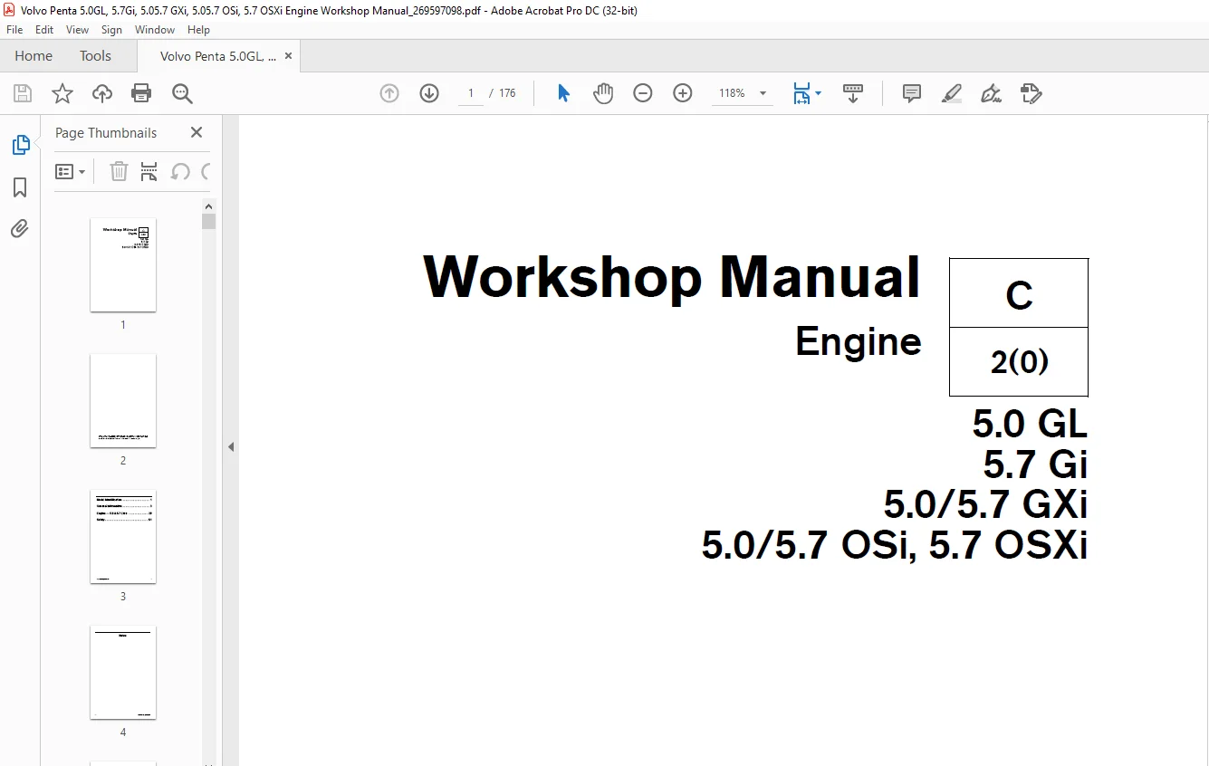
Volvo Penta Engine 5.0 GL 5.7 Gi 5.0/5.7 GXi 5.0/5.7 OSi, 5.7 OSXi Workshop Manual PDF
$26.95
Volvo Penta Engine 5.0 GL 5.7 Gi 5.0/5.7 GXi 5.0/5.7 OSi, 5.7 OSXi Workshop Manual – PDF DOWNLOAD
Description
Volvo Penta Engine 5.0 GL 5.7 Gi 5.0/5.7 GXi 5.0/5.7 OSi, 5.7 OSXi Workshop Manual – PDF DOWNLOAD
FILE DETAILS:
Volvo Penta Engine 5.0 GL 5.7 Gi 5.0/5.7 GXi 5.0/5.7 OSi, 5.7 OSXi Workshop Manual – PDF DOWNLOAD
Language : English
Pages : 176
Downloadable : Yes
File Type : PDF
IMAGES PREVIEW OF THE MANUAL:
TABLE OF CONTENTS:
Volvo Penta Engine 5.0 GL 5.7 Gi 5.0/5.7 GXi 5.0/5.7 OSi, 5.7 OSXi Workshop Manual – PDF DOWNLOAD
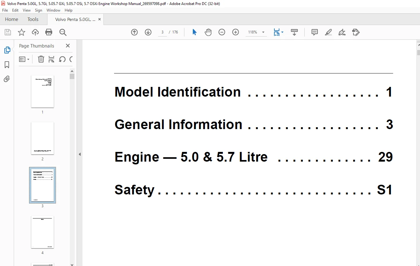
Model Identification 1 3
General Information 3 3
Engine – 5 0 & 5 7 Litre 29 3
Safety S1 3
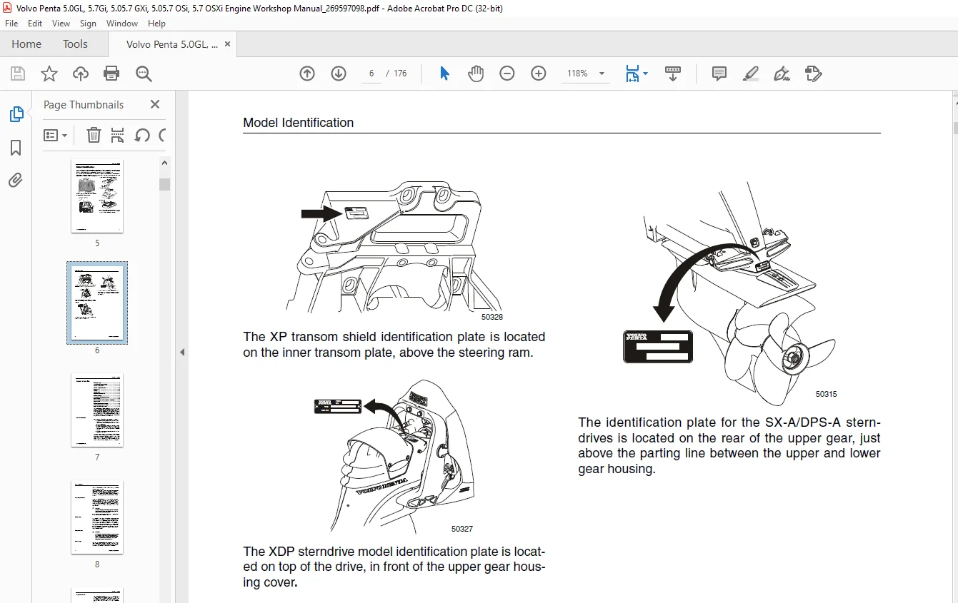
Model Identification 5
This workshop manual applies to the products listed in Service Bulletin 04-2-67 version 1 dated 08-2007 The unit that you are s 5
All sterndrive system components must be matched for either single or dual engine installations Failure to properly match engin 5
4 3, 5 0, and 5 7 Gi, GXi, OSi, OSXi models 5
8 1 Gi, GXi, OSi models 5
All GL models 5
General Information 7
Good Service Practice 7
Preparation for Service 8
Service Policy 8
Replacement Parts 8
Parts Catalogs 8
Special Service Tools 9
Product References, Illustrations & Specifications 9
Tuning the Engine 9
Engine Compression Testing 9
1 Visually inspect stern drive unit for leaks, missing parts or other obvious defects Replace deteriorated parts 10
2 Compression check: Proper compression is essential for good engine performance An engine with low or uneven compression cannot be properly tuned 10
To Prevent Sparking 10
Test Conclusion 10
1 If compression improves considerably, the piston rings are at fault 10
2 If compression does not improve, valves are sticking or seating poorly, or valve guides are worn 10
3 If two adjacent cylinders indicate low compression pressures and squirting oil on the pistons does not increase the compressi 10
Compression Pressure Limit in PSI 11
Ignition System Components 11
Fuel System Components 11
Intake Manifold Vacuum Testing 12
Test Procedures 12
1 Install a vacuum gauge to a good intake manifold source (usually at the PCV valve port), following the gauge manufacturer’s instructions Start and warm up the engine 12
2 Observe the vacuum gauge while operating the engine over a range of engine speeds 12
Test Results 12
1 A steady vacuum reading between 14 and 19in Hg (47-64 kPa) at idle indicates an engine in good mechanical condition 12
2 A vacuum reading below 14 in Hg (47 kPa) at idle, indicates an engine that is not developing enough vacuum Further testing for base mechanical problems is needed 12
3 Possible causes of low intake manifold vacuum are late ignition timing, low compression, poor engine sealing, leaks at vacuum lines and connections or bad MAP sensor 12
4 If the gauge fluctuates at idle, possible causes are sticking or leaking valves, or an ignition miss 12
5 If the gauge fluctuates at idle but smooths out as engine RPM increases, check for bad valves or camshaft 12
6 If the gauge fluctuates more with increases engine RPM, check for weak or broken valve springs, bad valves, ignition miss, or a leaking head gasket 12
7 If the vacuum gauge fluctuates regularly with each engine cycle, check for a bad valve 12
8 If the vacuum reading drops steadily as engine RPM increases, check the exhaust system between the engine and vertical drive for restrictions 12
9 See table and chart below and on the following page for more information 13
Vacuum Gauge Readings 13
Gasoline Requirements 14
Gasoline Containing Alcohol 14
Crankcase Oil 15
Draining and Filling the Engine Crankcase 15
Temperature Viscosity Recommendations 16
Crankcase Capacities 16
Oil Filter 16
Canister type 16
Replaceable Element Type 17
Power Steering 17
Steering System Lubrication 17
Power Trim/Tilt Fluid Level 17
Off-Season Storage 17
Limited Use 18
Storage 18
Step 1 Prepare a storage mixture 18
Step 2 Change Motor Oil and Oil Filter: 19
Step 3 Change Drive Lubricant: 19
Step 4 Fog Engine: 19
Step 5 Drain Cooling System 19
Front 19
1 Disable ignition system See Engine Compression Testing on page 5 19
2 Remove inlet and outlet hoses from raw water pump and crank the engine with starter 1-2 revolutions 19
3 Reconnect ignition system 20
Starboard 20
4 Disconnect and drain large hose at circulation pump 20
Port 20
5 Remove exhaust manifold drain plug Clear hole with a small wire to ensure complete drainage 20
6 Remove cap from engine flush hose and lower hose into bilge 20
Preparation for Boating After Storage 20
1 Install all drain plugs Install cooling hoses and clamps Check condition of hoses, manifold end caps and clamps Connect hoses to engine and tighten clamps securely Install boat drain plug, if removed 20
2 Remove the distributor cap and rotor Wipe the inside of the distributor cap dry with a clean cloth and spray with Corrosion Spray Replace the rotor and cap 20
3 Clean the battery terminals With the ignition switch in the “OFF” position, install the battery and attach the battery cables Spray terminals with Corrosion Spray 20
4 Open the fuel shut-off valve (if so equipped) and check all fuel line connections for leaks 20
5 Check the flame arrestor and clean if necessary Reinstall, make sure all parts are in place and tighten nut securely 20
6 Make a thorough check of the boat and engine for loose or missing nuts and screws Pump the bilge dry and air out the engine compartment 20
7 Test run engine: Launch boat or use a flushing adaptor installed on Sterndrive 20
8 With engine compartment open, start the engine Monitor the voltmeter, oil pressure and water temperature gauges frequently to be sure all systems are operating properly Check for fuel, oil, and water leaks 20
Engine Break-in 21
First Two Hours 21
Next Eight Hours 21
Final Ten Hours 21
1 Check crankcase oil level frequently Maintain oil level in safe range, between “add” and “full” marks on dipstick 21
2 Watch oil pressure gauge If gauge indication drops below the normal operating oil pressure range (See Engine Specifications 22
3 Watch engine temperature indicator to be sure there is proper water circulation 22
Operation After Break-in 22
Submerged Engine or Water Ingestion in Cylinders 22
1 Remove spark plugs immediately and crank engine to remove water from cylinders Do not attempt to crank engine with water present in cylinders, internal engine damage will result 22
2 Drain, flush and refill crankcase with new oil, See Draining and Filling the Engine Crankcase on page 11 22
3 Change oil filter, See Oil Filter on page 12 22
20-Hour Check 23
1 Change engine oil and oil filter 23
2 Check power trim/tilt reservoir for proper fluid level 23
3 Clean and inspect the ceramic filter located under the fuel pump 23
4 Check flame arrestor for proper mounting 23
5 Start engine and check complete fuel system for leaks 23
6 Lubricate steering cable ram with Volvo Penta grease P/N 828250 Check power steering pump reservoir for correct fluid level 23
7 Check shift system for proper adjustment and operation Verify cable attachment clamp on pivot housing is fully seated and secure Inspect cable anchor and cotter pin at shift linkage on stern drive for proper installation and free movement 23
8 Inspect exhaust system Tighten all hose clamps, and check for leaks Verify all clamps on exhaust and u-joint bellows are properly located and tightened 23
9 Check tension on drive belt 23
10 Check all engine mount screws, stern drive mounting nuts and transom shield mounting nuts for tightness 23
11 Check for any deficiencies, malfunctions, signs of abuse, etc Correction of any problems at this time will prevent the worsening of a minor problem and help ensure a trouble-free boating season 23
12 Check oil level in Sterndrive and add as necessary with GL-5 Synthetic Gear Lubricant or Mobilube 1 SHC Fully Synthetic SAE 75W-90 (meeting or exceeding MIL-L-2105C or D, API GL-4 or 5) gear lubricant 23
13 Make sure engine can achieve maximum rated RPM with normal load 23
Positive Closed Ventilation System 23
With Engine Idling 24
1 Remove PCV valve from its mounting, but leave vacuum inlet side connected to hose If the valve is functioning properly and n 24
2 Reinstall PCV valve, then remove crankcase air inlet hose at flame arrestor connection Loosely hold a small piece of stiff p 24
With Engine Stopped 24
Servicing PCV Valve 24
Troubleshooting – System Isolation 24
System Isolation 25
1 Discharged or dead Battery 25
2 Loose or corroded connections 25
3 Cranking System Troubleshooting Chart in the Electrical Ignition/ Fuel Service Manual 25
1 Distributor Cap 25
2 Coil and spark plug leads 25
3 Ignition timing 25
4 Automatic spark advance 25
5 Appropriate Ignition Troubleshooting Chart in the Electrical/Ignition/Fuel Service Manual 25
6 EFI Models: Refer to EFI Diagnostic Manual 25
1 Fuel Tank, valves, and lines 25
2 Fuel pump and filter 25
3 Carburetor and Filter 25
4 Boat Fuel System Troubleshooting Chart 25
5 Carburetor Troubleshooting Chart 25
6 Engine Fuel System Troubleshooting Chart 25
1 Compression 25
2 Ignition system 25
3 Fuel system and carburetor 25
4 Lubrication system 25
5 Cooling System 25
6 Sterndrive and propeller 25
7 PCV Valve 25
8 Engine Troubleshooting Guides 25
Engine Troubleshooting Guides 25
Engine Will Not Crank 26
Starter Circuit – Check: 26
Engine Cranks, But Will Not Start 26
Ignition Circuit 26
Fuel System 27
Cylinder Compression 27
Hard Starting – Cold Engine 27
Has Engine Always Done This? 27
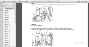
1 Carburetor choke operation and adjustment 27
2 Fuel lines for obstructions 27
3 For debris inside fuel tank 27
4 See Electrical/Ignition/Fuel System Service Manual 27
Was Engine Not Used For A Long Time? (more than two months) 27
1 For clean external canister and carburetor fuel filters 27
2 Empty carburetor float bowl due to evaporation 27
3 Water in fuel due to condensation 27
4 Fuel quality deterioration 27
5 See Electrical/Ignition/Fuel System Service Manual 28
Is This A New Condition? 28
1 Carburetor choke operation and adjustment 28
2 Carburetor accelerator pump 28
3 Fuel system for leaks, dirt, or obstructions 28
4 Engine timing and ignition system 28
5 See Electrical/Ignition/Fuel System Service Manual 28
Hard Starting – Hot Engine 28
Has Engine Always Done This? 28
1 Carburetor choke operation and adjustment 28
2 See Electrical/Ignition/Fuel System Service Manual 28
Is This A New Condition? 28
1 Brand, type or octane of fuel 28
2 Spark plugs 28
3 Water in fuel 28
4 Condition of battery and cables 28
5 Starter motor for overheat damage 28
Did Engine Refuse To Start After Being Run? 28
1 Ignition system primary circuit 28
2 Ignition coil(s)/ignition module 28
3 Engine timing 28
4 Carburetor choke operation and adjustment 28
5 See Electrical/Ignition/Fuel System Service Manual 28
Engine Runs Rough 28
If At Slow Speed 28
1 Idle speed and idle mixture 28
2 Engine timing and spark plugs 28
3 Fuel pump pressure 28
4 Water or contaminants in fuel 28
5 Carburetor or manifold vacuum leak 28
6 Internal carburetor fuel leak 29
7 See Electrical/Ignition/Fuel System Service Manual 29
If At High Speed 29
1 Air leak on suction side of fuel system 29
2 Too low octane fuel 29
3 Ignition system secondary circuit 29
4 Engine timing 29
5 Wrong model or size carburetor, improper main jets or power valve, defective secondary fuel circuit, secondary vacuum diaphragm failure 29
6 External canister and carburetor fuel filters 29
7 Fuel pump pressure 29
8 Engine compression 29
9 Water or contaminants in fuel, water in cylinders 29
10 See General Information section and Electrical/Ignition/ Fuel System Service Manual 29
Engine Noises and Vibrations 29
Valves – Hydraulic Lifters 29
1 Rapping only when starting (oil too heavy for prevailing weather, varnish on lifter, oil needs to be changed) 29
2 Intermittent rapping (leakage at lifter check ball) 29
3 Idle noise (excessive leak down rate, faulty check ball seat) 29
4 Generally noisy (excessive oil in crankcase, stuck lifter plunger) 29
5 Loud noise at operating temperature (scored lifter plunger, fast leak down rate, oil viscosity too light for prevailing weather or operating temperatures) 29
6 See appropriate Engine section 29
Ignition System (Ping or Knock) 29
1 Improper tuning 29
2 Incorrect spark plug wire routing 29
3 Use higher octane fuel 29
4 See Electrical/Ignition/Fuel Service Manual 29
Cooling System 29
1 Supply pump 29
2 Loose belts, pulleys 29
3 See Cooling System Manual 29
Mountings 29
1 Loose, broken or worn engine mounts 29
2 Loose lag screws holding mounts to stringer 29
Crankshaft Balancer or Flywheel 30
1 Loose bolt(s) 30
Alternator 30
1 Loose pulley, worn bearings 30
2 Loose mounting bolts 30
Sterndrive 30
1 Failed U-joints or gimbal bearing 30
2 Damaged internal drive components 30
3 Worn, bent or broken propeller hub or blades 30
4 Loose, worn or damaged engine coupler 30
Engine Overheats 30
1 Actual engine temperature by verifying with an accurate thermometer at the thermostat housing 30
2 Gauge operation and wiring circuit 30
3 Sending unit operation and wiring circuit 30
4 Supply pump, circulating pump and belt(s) 30
5 Water intake screens for blockage 30
6 Thermostat 30
7 Water supply hoses 30
8 Engine timing 30
9 Water leaks on pressure side of supply pump 30
10 Air leaks on suction side of supply pump including the transom shield and sterndrive 30
11 Engine compression 30
Engine Dies Out 30
Loss Of, Or Out Of, Fuel 30
1 Fuel gauge operation and wiring 30
2 Fuel level in tank 30
3 Water or debris in fuel 30
4 Fuel pickup tube and screen blockage 30
5 Fuel tank vent blockage 30
6 Plugged external canister or carburetor fuel filters 30
7 Air leak on suction side of fuel system 30
8 Fuel leak on pressure side of fuel system 30
9 Inoperative, restricted or incorrectly sized anti-siphon valve 30
10 Boat fuel lines too small in diameter 30
11 Fuel pump pressure and suction 30
12 Carburetor cleanliness and operation 31
13 See Electrical/Ignition/Fuel System Service Manual 31
Loss Of Ignition 31
1 Primary and secondary ignition circuits 31
2 Ignition switch 31
3 Circuit breakers 31
4 Wiring between engine and dash 31
5 Main engine harness wiring 31
6 See Electrical/Ignition/Fuel Service Manual 31
Engine Stops Or Dies Out Due To Seizure 31
1 Vertical drive for internal damage 31
2 Oil pressure gauge and crankcase oil level 31
3 Temperature gauge and cooling system operation 31
4 Internal engine components as required 31
Engine Won’t Reach Operating RPM 31
1 Propeller pitch or diameter, damaged blades, slipping hub 31
2 Crankcase oil volume 31
3 Marine growth on hull and drive 31
4 Fuel type or octane 31
5 Wrong Sterndrive gear ratio 31
6 Operating at high altitude 31
7 Restricted carburetor air intake 31
8 Restricted exhaust outlets in engine, transom bracket or drive 31
9 Poor cylinder compression 31
10 Carburetor size and type correct for engine 31
11 Fuel pump pressure and vacuum 31
12 Boat overloaded, or load improperly placed 31
13 Engine overheating 31
14 Engine timing and ignition system operation 31
15 Remote control cables and linkage for proper attachment and travel 31
Defective Engine Lubricating System 31
Engine Components 31
1 Clogged or incorrect oil filter 31
2 Worn oil pump gears, cover or shaft 31
3 Worn or collapsed oil pump relief valve spring, or foreign material caught on valve seat 32
4 Oil pump relief valve plunger loose in cover 32
5 Damaged filter bypass grommet 32
6 Clogged oil pickup screen, broken tube or housing 32
7 Plugged crankshaft or blocked oil galleys 32
8 Dirty or defective hydraulic lifters, clogged push rod passages 32
9 Poor quality, incorrect viscosity or quantity of oil 32
10 Oil level too high – too much oil in the crankcase 32
11 Incorrect hose routing on remote filter systems 32
12 Water in crankcase oil from condensation, defective head gasket, oil cooler, or cracked manifold/block water passages 32
Oil Pressure Warning System 32
1 Oil gauge/warning horn operation and wiring 32
2 Engine temperature 32
3 Oil pressure gauge and warning horn sender operation and wiring 32
4 Oil level too high or too low, oil level should be within the “Safe” range on the dipstick 32
Low Battery Voltage After Short Storage 32
Engine/Boat Components 32
1 All electrical accessories including ignition circuit off 32
2 Disconnect main battery negative cable from battery 32
3 Connect ammeter or voltmeter in series between negative battery cable and negative battery post 32
4 Disconnect main engine harness 10-Pin Connector 32
5 Repair or replace components as necessary 32
Engine – 5 0 & 5 7 Litre 33
General Description 34
Cylinder Block 34
Cylinder Head 34
Camshaft 35
Crankshaft 35
Pistons and Connecting Rods 35
Lubrication 35
Tools and Shop Equipment 35
Accessories 35
Cleaning 36
Draining The Engine 37
Raw Water Cooled Engines 37
1 With the engine turned off, locate and open the engine drain petcocks located on both sides of the engine block 37
2 Remove drain plugs from exhaust manifolds After the water has completely drained, reinstall the drain plugs and torque to 29 N m (22 lb ft ) 38
3 Note the hose orientation on the raw water pump Loosen the hose clamps and remove the hoses from the raw water pump 38
4 Crank the engine briefly, (1 or 2 crankshaft revolutions) but do not start the engine, to clear the water from the pump 38
5 Loosen the hose clamp on the large diameter hose and remove it from the circulation pump 38
6 Loosen the hose clamp on the lower fuel cell cooling line and remove hose from fuel cell Allow water to drain from hose 39
7 Reinstall all hoses and secure all clamps in the same orientation as removed 39
Draining seawater from the Closed Cooling System 39
1 With the engine turned off locate and loosen the lower drain cap from the heat exchanger (1) After water has completely drained, retighten the lower drain cap of the heat exchanger to 18-30ft lb (25-41 Nm) 39
2 Note the hose orientation on the raw water pump Loosen the hose clamps and remove the hoses from the raw water pump Crank t 39
3 Remove drain plugs from exhaust manifolds Probe the drains with a wire to ensure rust particles have not blocked the drain After water is completely drained, reinstall drain plugs and tighten securely 40
Engine Lubrication 40
4 Oil is drawn up through the oil pump screen and passes through the pump to the oil filter The oil filter is a full-flow pape 40
Exhaust Manifold 41
Removal 41
1 Drain water from exhaust manifolds 41
2 Disconnect water hose from manifold 41
3 Loosen upper exhaust hose clamps, then remove high rise elbow 41
4 Remove manifold attaching screws, then remove the manifold 41
Inspection 41
1 Inspect for cracks 41
2 To pressure check manifold, use a plate such as pictured, and a new elbow gasket to seal water passage in manifold Be sure t 41
Installation 41
1 Clean mating surfaces on manifold and head Install new exhaust gasket, then install manifold and secure with screws Tighten screws to 20-26 ft lb (27-35 N m) 41
2 Install a new gasket and high rise elbow to manifold Tighten bolts to 12-18 ft lb (16-24 N m) 42
3 Clean the gasket mounting surfaces on both the riser and the manifold 42
4 Use spray on gasket remover to remove ALL traces of riser gasket Heavy scrapping with tools on gasket surfaces may gouge surface, preventing proper seal 42
5 Follow pre-cautions on can of gasket remover to prevent damage to paint on manifold, riser or engine 42
6 Use 80 grit sandpaper and a sanding block, or equivalent to smooth the gasket mounting surfaces on the riser and manifold 42
7 Place gasket over mounting surface on manifold 43
8 Install riser, on to exhaust manifold 43
9 Make sure gasket is properly placed 43
10 Install bolts and washers to secure riser 43
11 Install any parts secured under bolts 43
12 Torque riser bolts in a crossing pattern to 40 Nm 43
13 (30 ft lb ) Make at least two passes to insure proper torque is reached 43
14 Install all other parts mounted to risers 43
15 Install exhaust hose and secure with clamps 43
16 Connect water hose and secure with clamp 43
17 Start engine and check for fuel leaks 43
Starter 43
Remove 43
1 Disconnect power from the engine 43
2 Remove battery cable (2) from solenoid extension nut 43
3 Remove solenoid extension nut (4) and cover (3) from solenoid 43
4 Remove accessory wires from solenoid (5) 43
5 Remove start wire nut (6) 43
6 Remove start wire from solenoid start terminal (7) 43
7 Remove starter mounting bolts 44
8 Remove starter 44
Installation 44
1 Hold stater against engine mounting pad with mounting holes aligned 44
2 Install starter bolts and tighten to 41-49 Nm (30-36 ft lb) 44
3 Connect accessory wires (5) to solenoid 44
4 Install solenoid extension nut (4) and washer on solenoid terminal Tighten to 19 – 28 N m (14 – 20 ft lb ) 44
5 Install solenoid extension nut cover (3) 44
6 Connect battery cable (2) to solenoid extension nut 44
7 Install battery cable bolt (1) and washer Tighten to 19 – 28 N m (14 – 20 ft lb ) 44
8 Install start wire (7) on solenoid stud “S” 44
9 Install start wire nut (6) and washer Tighten to 3 – 5 N m (26 – 44 in lb ) 44
10 Connect start wire to solenoid start terminal (1) 44
11 On GL models, connect the purple wire to the solenoid “R” terminal in the same manner 45
Intake Manifold 45
Removal 45
1 Disconnect power from engine 45
2 Drain water from engine block See Draining The Engine on page 33 45
3 If the engine has closed cooling installed, remove drain plugs from engine block Catch the coolant from the engine and dispose of properly 45
Disconnect: 45
4 Disconnect hoses from thermostat housing 45
5 Disconnect Throttle cable 45
a Remove cotter pin (1) and washer (2) and remove throttle cable from throttle lever 45
b Loosen and remove anchor block bolt (3) and nut (4) 45
c Release cable block (5) and trunnion (6) 45
6 Crankcase ventilation hose from rocker arm covers (both sides if applicable) 45
Remove: 45
1 Disconnect wire at temperature gauge sender unit and engine wiring harness from alternator 45
Remove Distributor, Gi and GXi Models 46
1 Disconnect distributor high tension leads and ignition primary lead from distributor cap 46
2 Remove the distributor cap bolts and discard 46
3 Remove the distributor cap 46
4 Mark the position of the rotor on the housing 46
5 Scribe a line on distributor housing and intake manifold for reassembly in the same position 47
6 Loosen hold down clamp and remove the distributor 47
7 Remove Distributor and discard Gasket 47
8 Disconnect and remove alternator 47
9 Remove Fuse box 47
10 Carburetor fuel line from carburetor and fuel pump or fuel lines from fuel rails To disconnect fuel lines from fuel rail, see Quick Connect Fitting Service in EFI Diagnostic Workshop Manual 47
11 Remove intake manifold attaching bolts Lift manifold from engine Discard front and rear seals and gaskets 48
Clean: 48
Disassemble Intake Manifold (Gi, GXi, OSi, & OSXi) 48
12 Remove Flame arrestor and bracket 48
13 Remove throttle body attaching studs 48
14 Remove throttle body and gasket Discard the gasket 48
15 Remove Thermostat housing bolts 49
16 Remove Thermostat housing and discard gasket 49
17 Remove MAT/MAP sensor stud and remove sensor from manifold 49
18 Remove four retaining studs and remove fuel rail assembly 49
19 Remove upper intake manifold attaching bolts 50
20 Remove upper intake manifold 50
21 Remove and discard upper intake manifold to lower intake manifold gasket 50
22 Remove impulse limiter 50
Clean and Inspect 50
1 Clean the upper intake manifold in cleaning solvent 50
2 Dry with compressed air 50
3 Clean the lower intake manifold in cleaning solvent 50
4 Dry with compressed air 50
Assemble Intake Manifold 51
1 If removed coat the threads of the impulse limiter with sealing compound P/N 1141570 51
2 Install impulse limiter into lower intake manifold and tighten to 14-19 N m (10-14 ft lb ) 51
3 Place a NEW upper intake manifold gasket into the upper intake manifold gasket groove 51
4 Place the upper intake onto the lower intake manifold 51
5 Install upper intake manifold bolts 51
6 Tighten the upper intake manifold bolts in two stages 51
7 Inspect O-rings on fuel injectors Replace any damaged, cut, or missing O-rings 51
8 Install the fuel injectors into the lower intake manifold 51
9 Install the fuel rail retaining studs and tighten to 51
Intake Manifold Installation 51
Install or Connect: 52
1 Apply a 4 0 mm (0 157 in) patch of adhesive Volvo Penta P/N 1161277 or equivalent to the cylinder head side of the lower intake manifold gasket at each end 52
2 Install the lower intake manifold gasket onto the cylinder head Use the gasket locator pins in order to properly seat the lower intake manifold gasket on the cylinder head 52
3 Apply a 5 0 mm (0 197 in) bead of adhesive Volvo Penta P/N 1161277 or equivalent to the front top of the engine block 52
4 Apply a 5 0 mm (0 197 in) bead of adhesive Volvo Penta P/N 1161277 or equivalent to the rear top of the engine block Extend the adhesive bead 13 mm (0 50 in) onto each lower intake manifold gasket 52
5 Install the intake manifold assembly onto the engine block 53
6 If reusing the fasteners, apply threadlock Volvo Penta P/N 1161053 or equivalent to the threads of the manifold bolts 53
7 Install the manifold bolts 53
Tighten: 53
8 Tighten the intake manifold bolts 53
a Tighten the bolts in sequence (1-8) on the first pass to 3 N m (27 lb in) 53
b Tighten the bolts in sequence (1-8) on the first pass to 12 N m (106 lb in) 53
c Tighten the bolts in sequence (1-8) on the first pass to 15 N m (11 lb ft ) 53
9 Connect fuel lines to fuel rail See Quick Connect Fitting Service on page 346 of EFI Diagnostic Workshop Manual 7742218 53
Distributor Installation 53
Gi and GXi models 54
1 Rotate the crankshaft balancer clockwise until the alignment marks on the crankshaft balancer (1) are aligned with the tabs on the engine front cover (2) and the number 1 piston is at top dead center of the compression stroke 54
2 If not already removed, remove and discard the distributor cap screws 54
3 Remove the distributor cap 54
4 Install NEW distributor gasket onto the distributor 54
5 Align the indent hole on the distributor gear with the paint mark on the distributor housing 55
6 Align the slotted tang in the oil pump driveshaft with the distributor driveshaft Rotate the oil pump driveshaft with a screwdriver if necessary 55
7 Align the flat (1) in the distributor housing toward the front of the engine 55
8 Install the distributor and distributor clamp The flat in the distributor housing must be pointing toward the front of the engine 56
9 Once the distributor is fully seated, align the distributor rotor segment with the number 8 pointer (1) that is cast into the distributor base 56
10 Install the distributor clamp bolt and Tighten the bolt to 25 N m (18 lb ft ) 56
11 Install the distributor cap and NEW distributor cap bolts Tighten the screws to 2 4 N m (21 lb in) 57
12 Set timing, GL Models see Electrical Fuel and Ignition Workshop Manual Gi and GXi Models see EFI Diagnostic Workshop Manual, On Board Repair 57
Alternator with mounting bracket 57
13 Install distributor cap and high tension leads See the General Information section in Electrical/Ignition/Fuel Service Manual for correct firing order and spark plug wire routing 57
14 Install oil pressure sending unit 57
Connect: 57
15 All electrical connections Apply black neoprene dip, or equivalent, on all exposed connections 57
16 Fuel lines to carburetor and fuel pump or throttle body and fuel pump/vapor separator 57
17 Throttle cable 57
18 All water hoses, and close all drain petcocks 57
19 Both crankcase ventilation hoses 57
20 Battery cables 57
21 Start engine Check ignition timing, carburetor idle speed and mixture Check for leaks 57
Rocker Arm Cover 58
Remove: 58
1 Valve rocker arm cover bolts 58
2 Valve rocker arm cover 58
3 Gasket 58
Clean: 58
a Parts in solvent Remove all sludge and varnish 58
b Old gaskets from the gasket surfaces 58
Inspect: 58
a Gasket flanges for bending or damage 58
b Rubber grommets and parts for deterioration 58
Installation 58
1 New gasket 58
2 Valve rocker arm cover 58
3 Valve rocker arm cover bolts 58
Tighten: 58
1 Valve rocker arm cover bolts to 106 in lb (12 N m) 58
Valve Train 58
Removal 58
1 Remove rocker arms 58
2 Remove pushrods and keep in order with the valve lifters and rocker arms 59
3 Remove valve lifter retainer bolts and valve guide retainer 59
4 Remove the valve guides and valve lifters 59
5 Remove the lifters one at a time using J 9290-01/J 3049 or equivalent and place them in an organizer rack 60
6 Store all reusable components in an exact order, so they may be reassembled in the same wear pattern location from which they were removed 60
Clean: 60
1 Mark, sort and organize the components for assembly 60
2 Clean the components with cleaning solvent 60
3 Dry the components with compressed air 60
Inspect: 60
4 Inspect the valve rocker arm components for the following: 60
5 Inspect the valve push rods for the following: 61
Valve Lifters and Guides Clean and Inspect 61
1 Mark, sort and organize the components for assembly 61
2 Clean the components with cleaning solvent 61
3 Dry the components with compressed air 61
4 Inspect the valve lifter pushrod guides (1) for excessive wear, cracks or damage 61
5 Inspect the valve lifter guide retainer for wear, damage or stress cracking in the leg areas (2) and wear or damage in the bolt holes (3) 61
6 Inspect the valve lifter for the following: 61
Installation 61
Valve Lifter Installation 62
1 Apply lubricant GM P/N 12345501 or equivalent to the valve lifter rollers 62
2 Install the valve lifters 62
Valve Lifter Pushrod Guides 62
3 Install the valve lifter pushrod guides 62
4 Tighten the valve lifter pushrod guide bolts to 25 N m (18 lb ft ) 62
Valve Push Rod 62
1 Install the valve pushrods 62
Install Rocker Arm Assemblies 63
2 Install the following components: 63
Valve Lash Adjustment 63
1 Turn the valve rocker arm nuts clockwise until all of the valve lash is removed 63
2 Turn the crankshaft clockwise until the alignment mark on the crankshaft balancer is aligned with the notch in the engine front cover tab 63
3 Look at the number 1 cylinder valves as the crankshaft balancer alignment mark approaches the notch in the engine front cover 63
4 With the engine in the number 1 cylinder firing position, adjust the exhaust valves for cylinder numbers 1, 3, 4, and 8 and the intake valves for cylinder numbers 1, 2, 5, and 7 using the following process: 63
5 Turn the crankshaft clockwise 1 revolution until the alignment mark on the crankshaft balancer is aligned with the notch in the engine front cover tab 64
6 With the engine in the number 6 cylinder firing position, adjust the exhaust valves for cylinder numbers 2, 5, 6 and 7 and the intake valve for cylinder numbers 3, 4, 6 and 8 using the following process: 64
Valve Rocker Arm Cover Installation 64
1 Install the NEW valve rocker arm cover gasket into the groove of the valve rocker arm cover 64
2 Install the NEW valve rocker arm cover bolt grommets into the valve rocker arm cover 64
3 Install the valve rocker arm cover onto the cylinder head 64
4 Install the valve rocker arm cover bolts 64
5 Tighten the valve rocker arm cover bolts to 12 N m (106 lb in) 64
Cylinder Head 64
Removal 64
1 Remove spark plugs 65
2 Remove cylinder head bolts 65
3 Remove cylinder heads 65
4 Remove and discard head gaskets 65
5 If required, remove the dowel pin (cylinder head locator) 66
Cylinder Head Disassemble and Recondition 66
Disassemble: 66
1 Compress the springs with J 8062 66
2 Remove the valve stem keys (1) 67
3 Remove the J 8062 from the cylinder head 67
4 Remove the valve spring cap (2) 67
5 Remove the valve spring (3) 67
6 Remove the valve stem oil seal (4) 67
7 Discard the valve stem oil seal 67
8 Remove the valve 67
Cylinder Head Clean and Inspect 67
Clean: 67
1 Clean the valve stems and cylinder heads on a buffing wheel 67
2 Clean the following components in cleaning solvent: 67
3 Dry the components with compressed air 67
4 Use the J 8089 to clean the carbon from the cylinder head combustion chambers 67
5 Inspect the cylinder head for the following: 67
Inspect: 68
6 Measure the cylinder head for warping with a straight edge and feeler gauge 68
Valve Spring Tension 68
1 Use the J 9666 in order to measure the valve spring 68
Valve Spring Straightness 68
2 Inspect the valve springs for Straightness 68
Valve Stems 69
3 Valve stems (1) with excessive valve guide (2) clearance must be repaired or the cylinder head replaced 69
4 Measure the valve stem-to-guide clearance 69
a Clamp the J 8001 on the exhaust port side of the cylinder head 69
b Position the dial indicator so that the movement of the valve stem from side to side (crosswise to the cylinder head) will ca 69
c Drop the valve head about 1 6 mm (0 063 in) off the valve seat 69
d Use light pressure and move the valve stem from side to side in order to obtain a valve stem-to-guide clearance reading 69
Valve Guide Reaming and Seat Grinding 70
Measuring: 70
1 Measure the valve stem-to-guide clearance See Cylinder Head Clean and Inspect on page 63 70
2 Improper valve stem (1) to valve guide (2) clearance may cause excessive oil consumption 70
Reaming: 71
3 Use the J 5830-3 in order to ream the exhaust valve guide in order to achieve the correct valve stem-to-guide clearance 71
4 Always recondition the exhaust valve seat after reaming the exhaust valve guide bores and installing new exhaust valves 71
Inspect 71
5 Inspect the valves for the following: 71
6 Inspect the valve contact surface for the following: 72
7 Reconditioning of the valves and valve seats: 72
Valve Rocker Arm Stud Removal 72
1 Place the J 5802-01 over the valve rocker arm ball stud to be removed 73
2 Install a nu and a flat washer 73
3 Rotate the clockwise t remove the valve rocker arm ball stud 73
Valve Rocker Arm Stud Installation 73
1 Ream the hole to the proper size for the replacement oversize valve rocker arm ball stud Use J 5715 for 0 0762 mm (0 003 in) oversize valve rocker arm ball studs or J 6036 for 0 03302 mm (0 013 in) oversize valve rocker arm ball studs 73
2 Apply lubricant GM P/N 1052271 or equivalent to the lower end (press-fit end) of the valve rocker arm ball stud 73
3 Use J 6880 and a hammer to install the valve rocker arm ball stud into place The valve rocker arm ball stud is installed to proper depth when the J 6880 bottoms onto the cylinder head 74
Cylinder Head Assemble 74
Install Oil Seal 74
1 Assemble the valve into the proper valve guide 74
2 Select the proper valve stem oil seal for the specific valve guide 74
3 Lubricate the valve stem oil seal and the outside diameter of the valve guide with clean engine oil 74
4 Assemble the valve stem oil seal onto the valve stem 74
5 Install the valve stem oil seal onto the valve guide using the J- 42073 Tap the valve stem oil seal onto the valve guide until the J- 42073 bottoms against the valve spring seat 75
6 Inspect the valve stem oil seal The valve stem oil seal should not be bottomed against the valve guide 75
Install Valve Spring 75
7 Install the valve spring (3) 75
8 Install the valve spring cap (2) onto the valve spring (3) and over the valve stem 75
9 Use the J 8062 in order to compress the valve springs 76
10 Install the valve stem keys 76
a Use grease in order to hold the valve stem keys in place while disconnecting the J 8062 76
b Look to ensure that the valve stem keys seat properly in the upper groove of the valve stem 76
c Tap the end of the valve stem with a plastic-faced in order to seat the valve stem keys, if necessary 76
Installation 76
1 Clean the cylinder head gasket surfaces on the engine block 76
2 Inspect the dowel pins (cylinder head locators) for proper installation 76
3 Clean the cylinder head gasket surfaces on the cylinder heads 76
4 Install NEW cylinder head gaskets in position over the locator pins 76
5 Install the cylinder head onto the cylinder block Guide the cylinder head carefully into position over the locator pins and the cylinder head gasket 77
6 Apply sealant 1141570 or equivalent to the threads of the cylinder head bolts 77
7 Install the cylinder head bolts finger tight 77
Tighten: 77
1 First step, 30 N m (22 ft lb ) 77
2 Final step use special tool J 36660 and tighten as follows; 77
a Tighten the long bolts (1, 2, 5, 6, 9, 10 and 13) on the final step sequence to 75 degrees 77
b Tighten the middle length bolts (14 and 17) on the final step sequence to 65 degrees 77
c Tighten the short length bolts (3, 4, 7, 8, 11, 12, 15 and 16) on the final step sequence to 55 degrees 77
3 Install New spark plugs adjusted to the proper gap 77
4 Install Rocker Arm Cover See Rocker Arm Cover on page 54 77
Oil Pan and OIl Pump 78
1 Drain oil from engine See Draining The Engine on page 33 78
2 Remove engine from boat See Removal and Installation Workshop Manual 78
Removal 78
3 Disconnect and remove the dipstick tube Discard the O-rings (1) and seals (2) 78
4 Remove the oil pan bolts and nuts 78
5 Remove the oil pan 78
6 Remove and discard the oil pan gasket 79
Oil Pan Clean and Inspect 79
1 Clean the oil pan baffle in cleaning solvent 79
2 Dry the oil pan and the oil pan baffle with compressed air 79
3 Inspect the oil 79
Oil Pump Removal 80
1 Remove the nuts (6) and the crankshaft oil deflector (2) 80
2 Remove the oil pump bolt (1) 80
3 Remove the oil pump (3), the oil pump driveshaft (5) and the oil pump driveshaft retainer (4) 80
4 Separate the oil pump (3), the oil pump driveshaft (5) and the oil pump driveshaft retainer (4) 80
5 Discard the oil pump driveshaft retainer 80
6 Inspect the pins (oil pump locator) for damage, and replace if required 80
Oil Pump Disassemble 81
1 Remove the oil pump driveshaft and retainer 81
2 Remove oil pump screen (if necessary) 81
3 Remove the oil pump cover bolts 81
4 Remove the oil pump cover 82
5 Remove the oil pump drive gear and the oil pump driven gear 82
6 Match mark the gears for reassembly 82
7 Remove the oil pressure relief valve retaining pin (1) 82
8 Remove the oil pressure relief spring (2) 82
9 Remove the oil pump pressure relief valve (3) 82
Oil Pump Clean and Inspect 82
1 Clean the oil pump components in cleaning solvent 82
2 Dry the components with compressed air 82
3 Inspect the oil pump for the following conditions: 82
4 If the oil pump is to be reused, install a NEW oil pump pressure relief valve spring 83
5 During oil pump installation, install a NEW oil pump driveshaft retainer 83
Oil Pump Assemble 83
1 Apply clean engine oil GM P/N 12345610 or equivalent to the oil pump pressure relief valve, oil pump pressure relief valve spring and oil pump body 83
2 Install the following items: 83
a The oil pump pressure relief valve 83
b The oil pump pressure relief valve spring 83
c The oil pump pressure relief valve spring straight pin 83
3 Apply clean engine oil GM P/N 12345610 or equivalent to the oil pump drive gear, the oil pump driven gear and the oil pump body internal surfaces 83
4 Install the oil pump drive gear and the oil pump driven gear into the oil pump body 83
a Align the match marks on the oil pump drive and driven gears 83
b Install the smooth side of the oil pump drive and driven gears toward the oil pump cover 83
5 Install the pump cover 84
6 Install the oil pump cover bolts Tighten the bolts to 12 N m (106 lb in) 84
7 Inspect the oil pump for smoothness of operation by turning the oil pump driveshaft by hand 84
8 Install the oil pump screen 84
a If removed, replace the oil pump screen 84
b The oil pump screen must have a good press fit into the oil pump body 84
c Mount the oil pump in a soft jawed vise 84
d Apply sealant 1141570 or equivalent to the end of the oil pump screen pipe 84
e Use the J 21882 and a soft-faced hammer in order to tap the oil pump screen into the pump body 84
9 The oil pump screen must align parallel with the bottom of the oil pan when the oil pan is installed 84
Oil Pump, Pump Screen and Deflector Installation 84
1 Inspect for properly installed pins (oil pump locator) 84
2 Assemble the oil pump (3), the oil pump driveshaft (5) and a NEW oil pump driveshaft retainer (4) 85
3 Install the oil pump (3) Position the oil pump onto the pins 85
4 Install the crankshaft oil deflector (2) and the nuts (6) 85
5 Install the bolt (1) attaching the oil pump to the rear crankshaft bearing cap 85
Tighten 85
Oil Pan Installation 85
1 Install the oil pan studs into the engine block if removed 85
Tighten 85
2 Tighten the oil pan studs to 6 N m (53 lb in) 85
3 Apply a 5 mm (0 197 in) wide and 25 mm (1 0 in) long bead of adhesive Volvo Penta P/N 1161277 or equivalent to both the right and left sides of the engine front cover to engine block junction at the oil pan sealing surfaces 86
4 Apply a 5 mm (0 197 in) wide and 25 mm (1 0 in) long bead of adhesive Volvo Penta P/N 1161277 or equivalent to both the right and left sides of the crankshaft rear oil seal housing to engine block junction at the oil pan sealing surfaces 86
5 Install the NEW oil pan gasket into the groove in the oil pan 86
6 Install the oil pan onto the engine block 87
7 Slide the oil pan back against a suitable straight edge 87
8 Using new seals and O-rings, install the dipstick tube Tighten bolt to 25 N m (18 ft lb ) 87
Water Pump 88
GXi 88
Removal 88
1 Release tension on the bent tensioner and remove the serpentine belt from the water pump pulley 88
2 Remove the bolts and the water pump pulley using the J41240 or suitable substitute 88
3 Remove the water pump bolts 88
4 Remove the water pump 88
5 Remove and discard the water pump gaskets 88
Inspection 88
Installation 89
1 If reusing the fasteners, apply sealant 1141570 or equivalent to the threads of the water pump bolts 89
2 Clean any residual gasket material from cooling ports on the engine If reusing the circulation pump, clean any residual gasket material from the face of the mounting ports 89
3 Install the water pump and the NEW water pump gaskets 89
4 Install the water pump bolts and tighten to 45 N m (33 lb ft ) 89
5 Install the fan and water pump pulley and bolts using the J41240 or suitable substitute 89
6 Tighten the and water pump pulley bolts to 25 N m (18 lb ft ) 89
7 Release the belt tensioner and reinstall the serpentine belt 89
GL 90
Remove 90
1 Loosen power steering pump nut 90
2 Loosen power steering pump bolt 90
3 Loosen power steering pump pivot nut 90
4 Pull up on power steering pump belt to loosen belt tension and remove the belt 90
5 Loosen alternator pivot bolt 91
6 Loosen alternator belt tension bolt 91
7 Pull on alternator belt to loosen the alternator and remove the belt 91
8 Remove the bolts and the fan and water pump pulley using the J41240 91
9 Remove the water pump bolts 91
10 Remove the water pump 91
11 Remove the water pump gaskets 91
12 Discard the water pump gaskets 91
Water Pump Installation 92
1 If reusing the fasteners, apply sealant 1141570 or equivalent to the threads of the water pump bolts 92
2 Install the water pump and the NEW water pump gaskets 92
3 Install the water pump bolts Tighten the water pump bolts to 45 N m (33 lb ft ) 92
4 Install the fan and water pump pulley and bolts using the J41240 Tighten the fan and water pump pulley bolts to 25 N m (18 lb ft ) 92
5 Install Alternator belt 92
6 Tighten alternator belt to 33,6 ± 2,7 N (75 ± 10 lb ) or 6,4 mm (¹ in ) deflection with light pressure on belt Check belt tension midway between the water pump pulley and the alternator pulley (2) 92
7 Install power steering pump belt 92
8 Tighten power steering belt to 33,6 ± 2,7 N (75 ± 10 lb ) or 6,4 mm (¹ in ) deflection with light pressure on belt Check belt tension midway between the water pump pulley and the power steering pump pulley (1) 92
Crankshaft Balancer 93
Removal 93
1 Disconnect hoses from raw water pump 93
2 Remove raw water pump retaining bolts and remove the pump 93
3 Remove water pump stay bracket 93
4 Remove the crankshaft balancer bolt and washer 94
5 Use the J23523-F in order to remove the crankshaft balancer 94
a Install the J 23523-F plate and bolts onto the crankshaft balancer Tighten the bolts to 25 N m (18 lb ft ) 94
b Install the J 23523-F forcing screw into the plate 94
c Rotate the J 23523-F forcing screw clockwise in order to remove the crankshaft balancer 94
6 Remove the J23523-F from the crankshaft balancer 94
Crankshaft Balancer Inspect 94
1 Clean the crankshaft balancer in cleaning solvent 94
2 Dry the crankshaft balancer with compressed air 94
3 Inspect the crankshaft balancer for the following: 94
Crankshaft Balancer Installation 94
1 Apply a small amount of adhesive Volvo Penta P/N 1161277 or equivalent onto the crankshaft balancer keyway in order to seal the crankshaft balancer keyway and crankshaft joint 95
2 Align the keyway of the crankshaft balancer with the crankshaft balancer key 95
3 Install the crankshaft balancer onto the end of the crankshaft 95
4 Use the J 23523-F in order to press the crankshaft balancer onto the crankshaft 95
a Install the J 23523-F plate and bolts onto the front of the crankshaft balancer Tighten the J23523-F plate bolts to 25 N m (18 lb ft ) 95
b Install the J 23523-F screw into the end for the crankshaft 95
c Install the J 23523-F bearing, the washer and the nut onto the J 23523-F screw 95
d Rotate the J 23523-F nut clockwise until the crankshaft balancer hub is completely seated against the crankshaft position sensor reluctor ring 95
5 Remove the J23523-F 95
6 Install the balancer bolt, lock washer, and centering washer Tighten the balancer bolt to 58 N m (43 lb ft ) 95
7 Install the water pump stay bracket 96
8 Install raw water pump and pulley Tighten bolts to 33-39 N m (25-29 ft lb ) 96
9 Install water pump retaining bracket 96
10 Install water hoses in the correct orientation and tighten clamps 96
Engine Front Cover 96
Removal 97
1 Remove the crankshaft position sensor bolt 97
2 Remove the crankshaft position sensor 97
3 Remove and discard the crankshaft position sensor seal (O- ring) 97
4 Remove engine front cover bolts and front cover 97
Engine Front Cover Installation 98
1 Install the NEW engine front cover 98
2 Install the engine front cover bolts and tighten to 12 N m (106 lb in) 98
3 Lubricate the NEW crankshaft position sensor seal (O-ring) with clean engine oil 98
4 Install the NEW crankshaft position sensor seal (O-ring) onto the crankshaft position sensor 98
5 Install the crankshaft position sensor until fully seated into the engine front cover 98
6 Install the crankshaft position sensor bolt and tighten to 9 N m (80 lb in) 98
7 Install oil pan, Oil Pan and OIl Pump on page 74 98
8 Install crankshaft balancer, Crankshaft Balancer on page 89 98
9 Install engine circulation pump, Water Pump on page 84 98
10 Install engine in boat, see Engine Removal and Installation Workshop Manual 98
Timing Chain and Sprocket 98
Removal 98
1 Remove engine front cover See Engine Front Cover on page 92 99
2 Remove the crankshaft position sensor reluctor ring 99
3 Check the camshaft timing chain free play 99
a Rotate the camshaft sprocket (1) counterclockwise until all slack is removed from the camshaft timing chain (2) 99
b Measure the free play on the slack side (3) of the camshaft timing chain If the camshaft timing chain can be moved side to side in excess of 11 mm (0 43 in), replacement of the camshaft timing chain and the sprockets is recommended during assembly 99
4 Remove the camshaft sprocket bolts 99
5 Remove the camshaft sprocket and the camshaft timing chain 99
6 Remove the crankshaft sprocket using the J 5825-A 100
7 Remove the crankshaft balancer key 100
Inspection 100
1 Clean the components with cleaning solvent 100
2 Dry the components with compressed air 100
3 Inspect the camshaft timing chain for binding or wear 100
4 Inspect the camshaft sprocket and the crankshaft sprocket for the following: 101
5 Inspect the crankshaft balancer key (1), the keyway (2) and the threaded hole (3) for damage 101
6 Repair or replace the crankshaft as necessary 101
Installation 101
1 Install the crankshaft balancer key into the crankshaft keyway 101
2 Align the keyway of the crankshaft sprocket with the crankshaft balancer key 102
3 Use the J 5590 to install the crankshaft sprocket 102
4 Rotate the crankshaft until the crankshaft sprocket is at the 12 o’clock position 102
5 Install the camshaft sprocket and the camshaft timing chain 102
6 Install the camshaft sprocket bolts and tighten to 25 N m (18 lb ft ) 102
7 Install the camshaft sprocket with the alignment mark at the 6 o’clock position 102
8 Install the crankshaft position sensor reluctor ring 103
a Align the keyway on the crankshaft position sensor reluctor ring with the crankshaft balancer key in the crankshaft 103
b Use the J 5590 in order to push the crankshaft position sensor reluctor ring onto the crankshaft until completely seated against the crankshaft sprocket 103
9 Install front cover See Engine Front Cover on page 92 103
Camshaft 103
Remove 103
1 Remove timing chain and sprockets, Timing Chain and Sprocket on page 94 103
2 Remove intake manifold, Intake Manifold on page 41 103
3 Remove valve lifters, Valve Train on page 54 103
4 Remove the camshaft retainer bolts and retainer 103
5 Remove the engine camshaft 103
a Install the three 5/16-18 x 4 0 inch bolts into the engine camshaft front bolt holes 103
b Using the bolts as a handle, carefully rotate and pull the engine camshaft out of the camshaft bearings 103
c Remove the bolts from the front of the engine camshaft 103
Inspect 103
1 Clean the engine camshaft in cleaning solvent 103
2 Dry the engine camshaft with compressed air 104
3 Inspect the camshaft retainer plate for damage 104
4 Inspect the camshaft bearings for correct fit into the engine block camshaft bearing bores 104
5 Inspect the camshaft bearings for excessive wear or scoring 104
6 Inspect the engine camshaft for the following: 104
7 Measure the engine camshaft journals with a micrometer 104
8 Measure for a bent engine camshaft or excessive engine camshaft run-out using the J 7872 104
a Mount the engine camshaft in a suitable stand between centers 104
b Use the J 7872 in order to check the intermediate engine camshaft journals 104
9 Measure the engine camshaft lobe lift using the J 7872 104
a Place the engine camshaft on the V-blocks 104
b Use the J 7872 in order to measure the engine camshaft lobe lift 104
10 Replace the engine camshaft if the engine camshaft lobe lift is not within specifications Refer to Engine Mechanical Specifications 104
Installation 105
1 Apply clean engine oil GM P/N 12345610 or equivalent, or engine oil supplement GM P/N 1052367 or equivalent to the following components: 105
2 Install three 5/16-18 x 4 0 in bolts into the engine camshaft front bolt holes 105
3 Use the bolts as a handle in order to install the engine camshaft 105
4 Remove the 3 bolts from the front of the engine camshaft 105
5 Install the timing chain and sprockets, See Timing Chain and Sprocket on page 94 105
6 Install the valve lifters, Valve Train on page 54 105
7 Install the intake manifold, See Intake Manifold on page 41 105
Camshaft Bearings 105
Remove 105
1 Remove camshaft, See Camshaft on page 99 105
2 Select the cone (1), the handle (10), the expanding driver (4-8), the washer (2 or 3) and the expander assembly (15) from the J 33049 105
3 Assemble the J 33049 105
4 Remove the camshaft inner bearings #2, #3 and #4 106
a Insert the J 33049 through the front of the engine block and into the camshaft inner bearing #2 106
b Tighten the J 33049 expander assembly nut until snug 106
c Push the J 33049 guide cone into the camshaft front bearing in order to align the J 33049 106
d Drive the camshaft inner bearing #2 from the camshaft inner bearing bore #2 106
e Loosen the J 33049 expander assembly nut 106
f Remove the camshaft inner bearing #2 from the J 33049 expander assembly 106
g Insert the J 33049 expander assembly into the camshaft inner bearing #3 106
h Tighten the J 33049 expander assembly nut until snug 106
i Push the J 33049 guide cone into the camshaft front bearing in order to align the J 33049 106
j Drive the camshaft inner bearing #3 from the camshaft inner bearing bore #3 106
k Loosen the J 33049 expander assembly nut 106
l Remove the camshaft inner bearing #3 from the J 33049 expander assembly 106
m Insert the J 33049 expander assembly into the camshaft inner bearing #4 106
n Tighten the J 33049 expander assembly nut until snug 106
o Push the J 33049 guide cone into the camshaft front bearing in order to align the J 33049 106
p Drive the camshaft inner bearing #4 from the camshaft inner bearing bore #4 106
q Loosen the J 33049 expander assembly nut 106
r Remove the camshaft inner bearing #4 from the J 33049 expander assembly 106
5 Remove the J 33049 from the engine block 106
6 Remove the camshaft outer bearings #1 and #5 107
a Insert the J 33049 into the camshaft outer bearing #1 107
b Tighten the J 33049 expander assembly nut until snug 107
c Drive the camshaft outer bearing #1 from the camshaft outer bearing bore #1 107
d Loosen the J 33049 expander assembly nut 107
e Remove the camshaft outer bearing #1 from the J 33049 expander assembly 107
f Remove the J 33049 from the engine block 107
g Insert the J 33049 expander assembly into the camshaft outer bearing #5 107
h Tighten the J 33049 expander assembly nut until snug 107
i Drive the camshaft outer bearing #5 from the camshaft outer bearing bore #5 107
j Loosen the J 33049 expander assembly nut 107
k Remove the camshaft outer bearing #5 from the J 33049 expander assembly 107
7 Remove the J 33049 from the engine block 107
8 Discard the camshaft bearings 107
Installation 107
1 Select the handle (10), the expanding driver (4-8), the washer (2 or 3) and the expander assembly (15) from the J 33049 107
2 Assemble the J 33049 107
3 Install the NEW camshaft outer bearings #5 and #1 108
a Install the NEW camshaft outer bearing #4 onto the J33049 expander assembly 108
b Tighten the J 33049 expander assembly nut until snug 108
c Align the camshaft outer bearing #5 lubrication hole with the oil gallery hole in the camshaft outer bearing bore #5 at the rear of the engine block 108
d Drive the camshaft outer bearing #5 into the camshaft outer bearing bore #5 at the rear of the engine block 108
e Loosen the J 33049 expander assembly nut 108
f Remove the camshaft outer bearing #5 from the J33049 expander assembly 108
g Install the NEW camshaft outer bearing #1 onto the J33049 expander assembly 108
h Tighten the J 33049 expander assembly nut until snug 108
i Align the camshaft outer bearing #1 lubrication hole with the oil gallery hole in the camshaft outer bearing bore #1 at the front of the engine block 108
j Drive the camshaft outer bearing #1 into the camshaft outer bearing bore #1 at the front of the engine block 108
k Loosen the J 33049 expander assembly nut 108
l Carefully slide the J 33049 into the engine block until the J 33049 expander assembly is positioned between the camshaft inner bearing bore #3 and the camshaft inner bearing bore #4 108
4 Install the NEW camshaft inner bearings #4, #3 and #2 108
a Install the NEW camshaft inner bearing #4 onto the J33049 expander assembly 108
b Tighten the J 33049 expander assembly nut until snug 108
c Align the camshaft inner bearing #4 lubrication hole with the oil gallery hole in the camshaft inner bearing bore #4 of the engine block 108
d Push the J 33049 guide cone into the camshaft front bearing bore #1 in order to align the J 33049 108
e Drive the camshaft inner bearing #4 into the camshaft inner bearing bore #4 108
f Loosen the J 33049 expander assembly nut 108
g Carefully slide the J 33049 until the J 33049 expander assembly is positioned between the camshaft inner bearing bore #3 and the camshaft inner bearing bore #2 109
h Install the NEW camshaft inner bearing #3 onto the J33049 expander assembly 109
i Tighten the J 33049 expander assembly nut until snug 109
j Align the camshaft inner bearing #3 lubrication hole with the oil gallery hole in the camshaft inner bearing bore #3 of the engine block 109
k Push the J 33049 guide cone into the camshaft front bearing bore #1 in order to align the J 33049 109
l Drive the camshaft inner bearing #3 into the camshaft inner bearing bore #3 109
m Loosen the J 33049 expander assembly nut 109
n Carefully slide the J 33049 until the J 33049 expander assembly is positioned between the camshaft inner bearing bore #2 and the camshaft outer bearing bore #1 109
o Install the NEW camshaft inner bearing #2 onto the J33049 expander assembly 109
p Tighten the J 33049 expander assembly nut until snug 109
q Align the camshaft inner bearing #2 lubrication hole with the oil gallery hole in the camshaft inner bearing bore #2 of the engine block 109
r Push the J 33049 guide cone into the camshaft front bearing bore #1 in order to align the J 33049 109
s Drive the camshaft inner bearing #2 into the camshaft inner bearing bore #2 109
t Loosen the J 33049 expander assembly nut 109
5 Install camshaft, See Camshaft on page 99 109
Piston, Connecting Rod, and Bearings 109
1 Remove engine from boat See Removal and Installation Workshop Manual 109
2 Remove cylinder heads See Cylinder Head on page 60 109
3 Remove oil pan See Oil Pan and OIl Pump on page 74 109
4 Use the J 24270 in order to remove the cylinder ring ridge 110
a Turn the crankshaft until the piston is at the bottom of the stroke 110
b Place a cloth on top of the piston 110
c Use the J 24270 to remove all of the cylinder ring ridge 110
d Turn the crankshaft so the piston is at the top of the stroke 110
e Remove the cloth 110
f Remove the cutting debris 110
5 Remove the connecting rod nuts 110
6 Remove the connecting rod cap 110
7 Use the J 5239 in order to protect the crankshaft journals and remove the connecting rod and the piston out of the top of the engine block 110
8 Remove the connecting rod bearings 111
a Keep the connecting rod bearings with the original connecting rod and connecting rod cap 111
b Wipe the oil from the connecting rod bearings 111
c Wipe the oil from the crankpin 111
Piston and Connecting Rod Disassemble 111
1 Remove the piston rings from the pistons 111
2 Press the piston pin from the connecting rod using the J 24086- C 112
3 The piston pin has an interference fit into the connecting rod, and is full floating in the piston 112
4 Mark separate, and organize the parts for assembly 112
Clean and Inspect 112
1 Clean the piston and connecting rod in solvent 112
2 Dry the components with compressed air 112
3 Clean the piston oil lubrication holes and slots 113
4 Inspect the piston for the following: 113
5 Inspect the piston pin for scoring, wear or other damage 113
6 Measure the piston ring-to-piston ring groove side clearance 113
d Insert the edge of the piston ring into the piston ring groove 113
e Roll the piston ring completely around the piston 113
7 Measure the piston ring side clearance with a feeler gauge 113
8 If the side clearance is too small, try another piston ring set 113
9 If the proper piston ring-to-piston ring groove clearance cannot be achieved, replace the piston and pin assembly 113
10 To determine the proper piston ring side clearance, Engine Specifications 5 0 Litre on page 139 113
11 To determine piston pin-to-bore clearance, use a micrometer and measure the piston pin 113
12 To determine piston pin-to-bore clearance, use an inside micrometer and measure the piston pin bore 114
13 To determine the piston pin-to-bore clearance, subtract the piston pin diameter from the piston pin bore diameter Engine Specifications 5 0 Litre on page 139 114
14 Measure the piston with a micrometer at a right angle to the piston pin bore, measure the piston at 11 mm (0 433 in) from the bottom of the skirt Engine Specifications 5 0 Litre on page 139 114
15 If the piston is not within specifications, replace the piston and pin as an assembly 114
16 Inspect the connecting rod for an out-of-round bearing bore Engine Specifications 5 0 Litre on page 139 114
17 Inspect the connecting rod for twisting 115
18 Inspect the connecting rod for damage to the bearing cap and bolt threads 115
19 Measure the piston compression ring end gap 115
20 Place the compression ring into the cylinder bore 115
a Push the compression ring into the cylinder bore to approximately 6 5 mm (0 25 in) above the ring travel The ring must be square to the cylinder wall 115
b Use a feeler gauge in order to measure the end gap 115
c Select another size ring set if the end gap exceeds specifications Engine Specifications 5 0 Litre on page 139 115
Piston Selection 115
1 Use the J 8087 in order to measure the cylinder bore diameter Measure at a point 64 mm (2 5 in) from the top of the cylinder bore and 90 degrees to the crankshaft centerline 115
2 Measure the J 8087 with a micrometer and record the reading 116
3 With a micrometer or caliper at a right angle to the piston pin bore, measure the piston 11 mm (0 433 in) from the bottom of the skirt 116
4 Subtract the piston diameter from the cylinder bore diameter in order to determine piston-to-bore clearance Engine Specifications 5 0 Litre on page 139 116
5 If the proper clearance cannot be obtained, then select another piston and measure the clearances 116
6 If the proper fit cannot be obtained, the cylinder bore may require honing or boring 116
7 When the piston-to-cylinder bore clearance is within specifications, permanently mark the top of the piston for installation into the proper cylinder 116
Piston and Connecting Rod Assemble 116
1 Install the piston pin and connecting rod assembly 116
a Lubricate the piston pin bores with clean engine oil 117
b Use a torch and apply MILD heat to the piston pin end of the connecting rod 117
c Use the J 24086-C in order to press the piston pin into the piston and connecting rod assembly 117
d Inspect for the proper installation of the piston and piston pin The piston must move freely on the piston pin with no binding or interference 117
2 Install the piston rings onto the piston 117
a Install the oil control piston ring spacer 117
b Install the lower oil control piston ring 117
c Install the upper oil control piston ring 117
d Install the lower compression piston ring 117
e Install the upper compression piston ring 117
3 Space the compression piston ring end gaps 120 degrees apart 117
4 Space the oil control piston ring end gaps a minimum of 90 degrees apart 117
Installation 118
1 Apply clean engine oil to the following components: 118
2 Install the J 5239 onto the connecting rod bolts 118
3 Install the J 8037 onto the piston and compress the piston rings 118
4 Install the piston and connecting rod assembly, with the J 8037 into the proper cylinder bore 118
5 Use the J 8037 and the J 5239 and lightly tap the top of the piston with a wooden hammer handle 119
a Hold the J 8037 firmly against the engine block until all of the piston rings have entered the cylinder bore 119
b Use the J 5239 in order to guide the connecting rod onto the crankshaft journal 119
6 Remove the J 5239 119
7 Install the connecting rod caps, bearings and nuts 119
a Tighten the nuts evenly on the first pass to 27 N m (20 ft lb ) 119
b Use the J 36660 or an equivalent angle torque meter to tighten the nuts on the final pass an additional 70 degrees 119
8 After the piston and connecting rod assemblies have been installed, then lightly tap each connecting rod assembly (parallel to the crank pin) in order to ensure that the connecting rods have side clearance 120
9 Use a feeler gauge or a dial indicator to measure the connecting rod side clearance between the connecting rod caps The connecting rod side clearance should be 0 15-0 44 mm (0 006- 0 017 in) 120
10 Install oil pan, Oil Pan and OIl Pump on page 74 120
11 Install cylinder heads, Cylinder Head on page 60 120
12 Install engine in boat, Engine Specifications 5 0 Litre on page 139 120
Engine Coupler 120
Removal 120
1 Remove engine from boat, Engine Specifications 5 0 Litre on page 139 120
2 Take out screws holding flywheel housing cover, then slide out cover 120
3 Remove nut, lock washer, and ground leads from ground stud and coil bracket Remove inner nut, lock washer and washer 120
4 Remove nut, lock washer, and ground leads from ground stud and power steering cooler bolt 121
5 Unscrew remaining flywheel housing bolts, lock washers and washers Note position of clamps so they can be installed in original position 121
6 Lift flywheel housing off engine block and set aside 121
7 Unscrew six locknuts, then pull coupler off flywheel 121
Inspection 121
Installation 122
1 Slide coupler onto crankshaft studs Install new locknuts 122
2 Tighten nuts in sequence Use a crowfoot wrench and tighten nuts to 40-45 ft lb (54-61 N m) 122
3 Install flywheel housing Place clamps in their original positions, and attache coil bracket and power steering cooler Tighten screws to 38-49 N m (28-36 ft lb ) 122
4 Place washer, lock washer and nut on ground stud Tighten inner nut to 47-54 N m (35-40 ft lb ) Attach electrical leads to ground stud Install lock washer and tighten outer nut securely Install ground stud hardware on opposite side of block 122
5 Slide flywheel cover into place Install screws and tighten them to 7-9 N m (60-84 in lb ) 123
6 Install engine, see Engine Installation and Removal Workshop Manual 123
Flywheel 123
Removal 123
1 Engine coupler, Engine Coupler on page 116 123
2 Remove flywheel from crankshaft studs 123
3 Note the position of any flywheel weights for assembly (if applicable) 123
Inspection 124
4 Inspect the engine flywheel for the following: 124
5 The ring gear has an interference fit onto the engine flywheel and the ring gear should be positioned completely flat against the flange of the engine flywheel 124
Installation 124
6 Install flywheel on crankshaft studs 124
7 Install engine coupler, Engine Coupler on page 116 124
Crankshaft Rear Oil Seal and Housing 124
Remove 124
1 Remove engine from boat See Engine Removal and Installation Workshop Manual 124
2 Remove engine coupler, See Engine Coupler on page 116 124
3 Remove flywheel, See Flywheel on page 119 124
4 Remove the crankshaft rear oil seal from the crankshaft rear oil seal housing 124
5 Discard the crankshaft rear oil seal 124
6 Remove the crankshaft rear oil seal housing nut and bolts 125
7 Remove the crankshaft rear oil seal housing 125
8 Remove the crankshaft rear oil seal housing gasket 125
9 Discard the crankshaft rear oil seal housing gasket 125
10 If necessary, remove the spring type pin 125
Installation 125
1 Install the crankshaft rear oil seal housing retainer stud and tighten to 6 N m (53 lb in) 125
2 Install the NEW crankshaft rear oil seal housing gasket 125
3 Install the crankshaft rear oil seal housing onto the crankshaft rear oil seal housing retainer stud 126
4 Install the crankshaft rear oil seal housing nut and bolts Tighten nut and bolts to 12 N m (106 lb in) 126
5 Apply a small amount (2 to 3 drops) of clean engine oil to the bore of the crankshaft rear oil seal housing 126
6 Apply a small amount (2 to 3 drops) of clean engine oil to the outside diameter of the engine flywheel pilot flange 126
7 Apply a small amount (1 drop) of clean engine oil to the outside diameter of the flywheel locator pin 126
8 Apply a small amount (2 to 3 drops) of clean engine oil to the crankshaft seal surface 126
9 Inspect the J 35621-B flange for imperfections that may damage the crankshaft rear oil seal 126
10 Remove the sleeve from the crankshaft rear oil seal 126
11 Apply a small amount (2 to 3 drops) of clean engine oil to the outside diameter of the crankshaft rear oil seal 126
12 Install the crankshaft rear oil seal onto the J 35621-B 126
13 Install the J 35621-B onto the rear of the crankshaft and hand tighten the tool bolts until snug 126
14 Install the crankshaft rear oil seal onto the crankshaft and into the crankshaft rear oil seal housing 126
a Turn the J 35621-B wing nut clockwise until the crankshaft rear oil seal is installed near to flush and square to the crankshaft rear oil seal housing 126
b Turn the J 35621-B wing nut counterclockwise to release the J 35621-B from the crankshaft rear oil seal 126
15 Remove the J 35621-B from the crankshaft 126
16 Wipe off any excess engine oil with a clean rag 126
17 Install oil pan if removed See Oil Pan and OIl Pump on page 74 126
18 Install flywheel See Flywheel on page 119 127
19 Install engine coupler See Engine Coupler on page 116 127
20 Install engine in boat See Engine Specifications 5 0 Litre on page 139 127
Crankshaft 127
Remove 127
1 Remove engine from boat See Removal and Installation Workshop Manual 127
2 Remove cylinder heads See Cylinder Head on page 60 127
3 Remove oil pan See Oil Pan and OIl Pump on page 74 127
4 Remove pistons and connecting rods See Piston, Connecting Rod, and Bearings on page 105 127
5 Remove timing chain and sprocket See Timing Chain and Sprocket on page 94 127
6 Remove starter See Starter on page 39 127
7 Remove engine coupler See Engine Coupler on page 116 127
8 Mark or identify the crankshaft bearing cap locations, direction and positions for assembly 127
9 Remove the crankshaft bearing cap bolts 127
10 Remove the crankshaft bearing caps 127
11 Remove the crankshaft 127
12 Remove the crankshaft bearings from the crankshaft bearing caps 128
13 Remove the crankshaft bearings from the engine block 128
Crankshaft and Bearings Clean and Inspect 128
1 Clean the crankshaft in cleaning solvent Remove all sludge or restrictions from the oil passages 128
2 Dry the crankshaft with compressed air 128
3 Clean the crankshaft bearings in cleaning solvent Wipe the crankshaft bearings clean with a soft cloth 128
4 Dry the crankshaft bearings with compressed air 128
5 Inspect the crankshaft for the following: 129
6 Inspect the crankshaft balancer key (1), the keyway (2) and the threaded hole (3) for damage Repair or replace the crankshaft as necessary 129
7 Measure the crank pins for out-of-round and taper Engine Specifications 5 0 Litre on page 139 129
8 Use a suitable support to support the crankshaft on the front and rear journals 129
9 Use the J 7872 in order to measure the crankshaft journal run out The crankshaft run out should not exceed 0 025 mm (0 0010 in) 129
10 Measure the crankshaft end play 130
a With the crankshaft pushed forward, insert a feeler gauge between the crankshaft and the crankshaft bearing surface and then measure the clearance Refer to Engine Mechanical Specifications 130
b If the correct end play cannot be obtained, verify that the correct size crankshaft bearing has been installed Engine Specifications 5 0 Litre on page 139 130
c Inspect the crankshaft for binding Turn the crankshaft to check for binding If the crankshaft does not turn freely, then loosen the crankshaft bearing cap bolts, one bearing cap at a time, until the tight crankshaft bearing is located 130
11 Inspect the crankshaft bearings for craters or pockets Flattened sections on the crankshaft bearing halves also indicate fatigue 130
12 Inspect the crankshaft bearings for excessive scoring or discoloration 130
13 Inspect the crankshaft bearings for dirt or debris imbedded into the crankshaft bearing material 130
14 Inspect the crankshaft bearings for improper seating indicated by bright, polished sections of the crankshaft bearings 131
Bearing Clearance Measuring Procedures 131
Micrometer Method for Crankshaft Bearings 131
1 Measure the crankshaft journal diameter with a micrometer in several places, approximately 90 degrees apart, and then average the measurements 131
2 Determine the taper and the out-of-round of the crankshaft journal See Engine Specifications 5 0 Litre on page 139 131
3 Install the crankshaft bearings into the engine block 131
4 Install the crankshaft bearings into the crankshaft bearing caps 132
5 Install the crankshaft bearing caps in the original positions and with the arrow on the crankshaft bearing caps in the direction of the front of the engine block 132
6 Install the crankshaft bearing cap bolts 132
a Tighten the crankshaft bearing cap bolts and the crankshaft bearing cap studs on the first pass to 20 N m (15 lb ft ) 132
b Tighten the crankshaft bearing cap bolts and the crankshaft bearing cap studs on the final pass an additional 73 degrees using the J 36660 angle torque meter 132
7 Measure the bearing inside diameter (ID) at two points 90 degrees apart Average the measurements 132
8 In order to determine the bearing clearance, subtract the average journal diameter from the average bearing inside diameter 132
9 Compare the crankshaft bearing clearance to the specifications See Engine Specifications 5 0 Litre on page 139 132
10 If the crankshaft bearing clearances exceeds specifications, install the new crankshaft bearings as follows: 132
a Measure the crankshaft bearing inside diameter (ID) at the top and the bottom using an inside micrometer 132
b Compare the crankshaft bearing clearance to the specifications See Engine Specifications 5 0 Litre on page 139 132
11 Replace or repair the crankshaft if the proper clearances cannot be obtained 132
Measuring Crankshaft Bearing Clearances (Plastic Gauge Method) 132
1 Install the crankshaft bearings into the engine block 132
2 Install the crankshaft 133
3 Install the gauging plastic the full width of the journal 133
4 Install the crankshaft bearings into the crankshaft bearing caps 133
5 Install the crankshaft bearing caps in the original positions and with the arrow on the crankshaft bearing caps in the direction of the front of the engine block 134
6 Install the crankshaft bearing cap bolts 134
a Tighten the crankshaft bearing cap bolts on the first pass to 20 N m (15 lb ft ) 134
b Tighten the crankshaft bearing cap bolts on the final pass an additional 73 degrees using the J 36660 134
7 Remove the crankshaft bearing cap bolts 134
8 Remove the crankshaft bearing caps The gauging plastic may adhere to either the crankshaft-bearing journal or the crankshaft-bearing surface 134
9 Without removing the gauging plastic, measure the compressed width at the widest point using the graduated scale on the edge of the gauging plastic envelope 134
10 Remove the flattened gauging plastic 134
11 Measure the remaining crankshaft bearing journals 134
Crankshaft and Bearings Installation 135
1 Install the crankshaft bearings into the engine block 135
2 Apply clean engine oil to the crankshaft bearings 135
3 Apply clean engine oil to the crankshaft bearing journals 135
4 Install the crankshaft 135
5 Install the crankshaft bearings into the crankshaft bearing caps 135
6 Apply clean engine oil to the crankshaft bearings 135
7 Install the crankshaft bearing caps in the original position and with the arrow on the crankshaft bearing caps in the direction of the front of the engine block 136
8 Install the crankshaft bearing cap bolts and the crankshaft bearing cap studs 136
9 Thrust the crankshaft rearward in order to set and align the crankshaft thrust bearings and the crankshaft bearing caps 136
10 Thrust the crankshaft forward in order to align the rear faces of the crankshaft thrust bearings 136
11 Look to ensure that the crankshaft bearing caps are fully seated in the engine block crankshaft bearing cap channel and that the crankshaft bearing caps are centered on the engine block bulkheads 136
12 Tighten the crankshaft bearing cap bolts 136
a Tighten the crankshaft bearing cap bolts on the first pass to 20 N m (15 lb ft ) 136
b Tighten the crankshaft bearing cap bolts on the final pass an additional 73 degrees using the J 36660 136
13 Measure the crankshaft end play 136
a Firmly thrust the crankshaft rearward, and then forward 136
b With the crankshaft pushed forward, insert a feeler gauge between the crankshaft and the crankshaft rear bearing thrust surface to measure the clearance Crankshaft end play 0 05-0 20 mm (0 002-0 008 in) 136
14 Rotate the crankshaft in order to check for binding 136
15 If the crankshaft does not turn freely, loosen the crankshaft bearing cap bolts on 1 crankshaft bearing cap at a time in order to determine the location of the binding 136
16 Install pistons and connecting rods See Piston, Connecting Rod, and Bearings on page 105 136
17 Install cylinder heads See Cylinder Head on page 60 136
18 Install intake manifold See Intake Manifold on page 41 136
19 Install oil pan See Oil Pan and OIl Pump on page 74 136
20 Install timing chain and sprocket See Timing Chain and Sprocket on page 94 136
21 Install flywheel See Flywheel on page 119 137
22 Install engine coupler See Engine Coupler on page 116 137
23 Install starter See Starter on page 39 137
24 Install engine in boat See Removal and Installation Workshop Manual 137
Recondition Engine Block 137
Engine Block Plug 137
Removal 137
1 Remove the engine oil pressure sensor and fitting 137
2 Remove the dowel straight pins (if required) 137
3 Remove the S type pin 137
4 Remove the square socket plugs (engine block oil gallery) from the rear of the engine block 138
5 Remove the left side rear and left rear top engine block oil gallery plugs 138
6 Remove the expansion cup plug (camshaft rear bearing hole) and discard 138
7 Remove the engine block oil gallery plugs (front) from the engine block and discard 138
8 Remove the spring type S pin (crankshaft rear oil seal housing locator if required) 139
9 Remove the engine block core hole plugs 139
a Use a suitable tool in order to drive the engine block core hole plugs into the coolant jacket 139
b Use a suitable tool in order to pull the engine block core hole plugs from the coolant jacket 139
c Discard the engine block core hole plugs 139
Engine Block Clean and inspect 140
1 Clean all the remaining sealing or gasket material from the sealing surfaces 140
2 Clean the engine block with cleaning solvent 140
3 Flush the engine block with clean water or steam 140
4 Clean the cylinder bores 140
5 Clean the oil galleries and the oil passages 140
6 Clean the scale and the deposits from the coolant passages 140
7 Clean the engine block cylinder head bolt holes 140
8 After cleaning the engine block, spray or wipe the cylinder bores and the machined surfaces with clean engine oil 140
9 Inspect the following areas: 140
10 Measure the cylinder bores for taper and out-of-round 141
a Depress the plunger on the J 8087 7 mm (0 275 in) or until the J 8087 enters the cylinder bore 141
b Center the J 8087 in the cylinder bore and turn the indicator dial to 0 141
c Move the J 8087 up and down the cylinder bore to determine the cylinder bore taper See Engine Specifications 5 0 Litre on page 139 141
d Turn the J 8087 to different points around the cylinder bore to determine the cylinder bore out-of-round condition Engine Specifications 5 0 Litre on page 139 141
Cylinder Boring and Honing 141
Honing Procedure 141
1 When honing the cylinder bores, follow the manufacturer’s recommendations for equipment use, cleaning and lubrication 141
2 During the honing operation, thoroughly check the cylinder bore 141
3 When honing to eliminate taper in the cylinder bore, use full strokes the complete length of the cylinder bore 141
4 Repeatedly check the measurement at the top, the middle and the bottom of the cylinder bore 141
5 By measuring the selected piston at the sizing point and then by adding the average of the clearance specification, the final cylinder bore honing dimension required can be determined 141
6 When finished, the reconditioned cylinder bores should have less than or meet the specified out-of-round and taper requirements 141
7 After the final honing and before the piston is checked for fit, clean the cylinder bore with hot water and detergent 141
a Scrub the cylinder bores with a stiff bristle brush 142
b Rinse the cylinder bores thoroughly with clean hot water 142
c Dry the cylinder bores with a clean rag 142
d Do not allow any abrasive material to remain in the cylinder bores 142
8 Perform final measurements of the piston and the cylinder bore 142
9 Permanently mark the top of the piston for the specified cylinder to which it has been fitted 142
10 Apply clean engine oil to each cylinder bore in order to prevent rusting 142
Boring Procedure 142
1 Before starting the honing or boring operation, measure all the new pistons with the micrometer contacting at points exactly 90 degrees from the piston pin centerline 142
2 Thoroughly clean the top of the cylinder block in order to remove any dirt or burrs before using any type of boring bar 142
3 Follow the instructions furnished by the manufacturer regarding the use of the boring equipment 142
4 When boring the cylinders, make sure all the crankshaft bearing caps are installed in the original position and direction 142
5 Tighten the crankshaft bearing caps to the proper torque specifications in order to avoid distortion of the cylinder bores in the final assembly 142
6 When making the final cut with the boring bar, leave 0 03 mm (0 001 in) on the cylinder bore diameter for finish honing This 142
Engine Specifications 5 0 Litre 143
Engine Mechanical Specifications 5 0 litre 143
Engine Specifications 5 7 Litre 147
Engine Mechanical Specifications 5 7 litre 147
Fastener Tightening Specifications 151
Fastener Tightening Specifications 151
Sealants, Adhesives and Lubricants 154
Sealants, Adhesives and Lubricants 154
Tune Up Specifications 154
Tune Up Specifications 5 0GL, 5 7GL 154
Tune Up Specifications 5 0GXi, 5 0OSi, 5 7Gi, 5 7OSi, 5 7GXi, 5 7OSXi 155
Special Tools 156
J 3049-A 156
Valve Lifter Remover 156
J 7872 156
Magnetic Base Dial Indicator 156
J 5239 156
Connecting Rod Bolt Guide Set 156
J 8001 156
Dial Indicator 156
J 5590 156
Crankshaft Gear Installer 156
J 8037 156
Piston Ring Compressor 156
J 5825-A 156
Crankshaft Gear Remover 156
J 8062 156
Valve spring compressor 156
(head off the engine) 156
J 5830-02 157
Valve Guide Reamer Set 157
J 8087 157
Cylinder Bore Gauge 157
J 8089 157
Carbon removing brush 157
J 24086-C 157
Piston Pin Remover/Installer Set 157
J 9666 157
Valve Spring Tester 157
J 24270 157
Ridge Reamer 157
J 21882 157
Oil Suction Pipe Installer 157
J 33049 157
Camshaft Bearing 157
Service Kit 157
J 23523-F 157
Balancer Remover and Installer 157
J 35621-B 157
Crankshaft Rear Oil Seal Installer 157
J 36660 158
Electronic Torque 158
Angle Meter 158
J 8520 158
Camshaft Lobe Lift Indicator 158
J 5802-01 158
Rocker Arm Stud Remover 158
J 41240 158
Fan Clutch Remover and 158
Installer 158
J 42073 158
Valve Stem Seal Installer 158
J 23738-A Vacuum pump 158
J 6880 158
Rocker Arm Stud Installer 158
o 158
J 28428-E 158
High Intensity Black 158
Light Kit 158
J 38606 159
Valve spring compressor 159
(head on the engine) 159
J 35468 159
Engine Front Cover Aligner and Oil Seal Installer 159
J 3936-03 159
Piston Ring Groove Cleaner 159
J 5892-D 159
Valve Spring Compressor 159
J 5715 or J 6036 159
Reamer 159
J 22794 159
Spark Plug Port Adapter 159
Volvo Penta Special Tool 159
888863 159
Distributor hold down tool 159
J 43276 159
Clutch Pilot Bearing 159
Remover 159
Customer Support: [email protected]
S.V 08/24