Volvo Penta TAD950VE TAD951VE TAD952VE TAD1250VE TAD1251VE TAD1252VE TWD1643GE Workshop Manual – PDF DOWNLOAD
Original price was: $86.95.$28.95Current price is: $28.95.
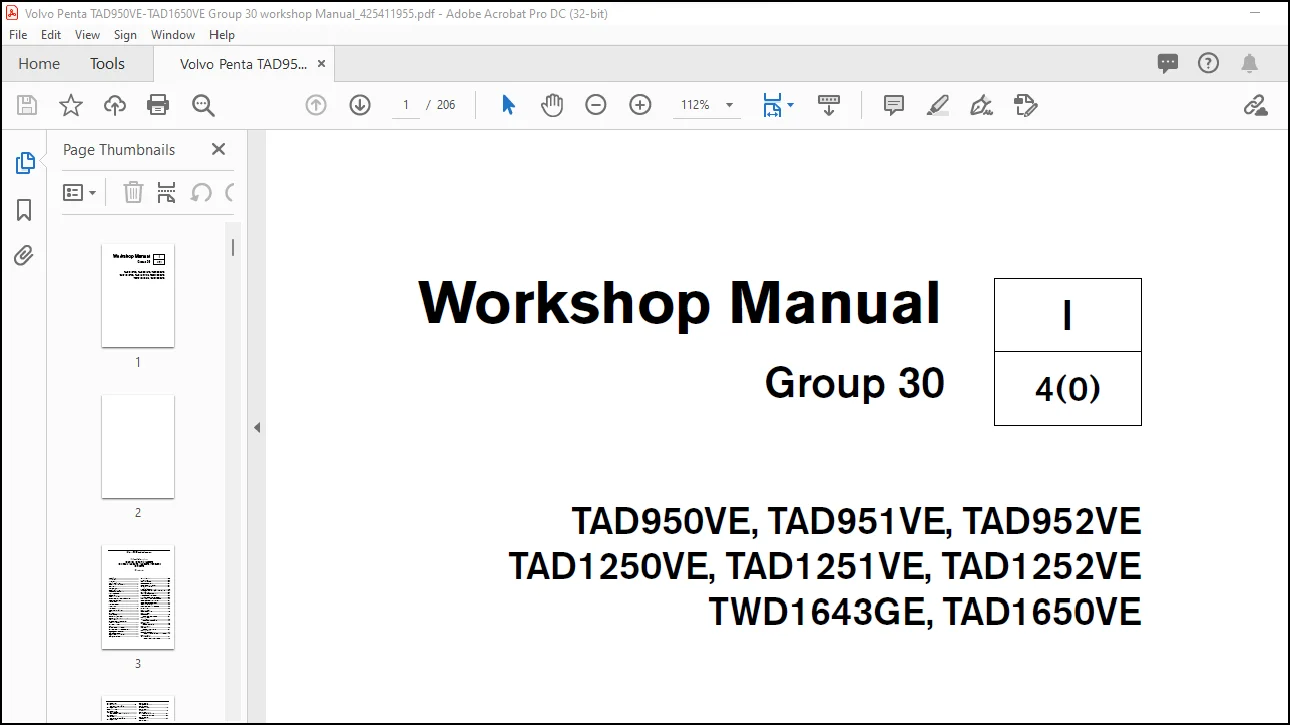
Volvo Penta TAD950VE TAD951VE TAD952VE TAD1250VE TAD1251VE TAD1252VE TWD1643GE TAD1650VE Workshop Manual_425411955 – PDF DOWNLOAD
Description
Volvo Penta TAD950VE TAD951VE TAD952VE TAD1250VE TAD1251VE TAD1252VE TWD1643GE Workshop Manual – PDF DOWNLOAD
FILE DETAILS:
Volvo Penta TAD950VE TAD951VE TAD952VE TAD1250VE TAD1251VE TAD1252VE TWD1643GE TAD1650VE Workshop Manual_425411955 – PDF DOWNLOAD
Language : English
Pages : 206
Downloadable : Yes
File Type : PDF
Size: 4.44 MB
IMAGES PREVIEW OF THE MANUAL:
DESCRIPTION:
Volvo Penta TAD950VE TAD951VE TAD952VE TAD1250VE TAD1251VE TAD1252VE TWD1643GE TAD1650VE Workshop Manual_425411955 – PDF DOWNLOAD
Introduction:
- This workshop manual contains technical data, descriptions and repair instructions for the Volvo Penta products or product versions noted in the table of contents.
- Check that you have the correct Workshop Manual for your engine. Read the available safety information, ”General information” and ”Repair instructions” in this workshop manual before you start to do any service work.
General information:
About this Workshop Manual:
This workshop manual contains descriptions and repair instructions for the standard versions of the TAD950VE, TAD951VE, TAD952VE, TAD1250VE, TAD1251VE, TAD1252VE and TWD1643GE engines. The workshop manual can illustrate tasks done on any of the engines noted above.
- This means that the illustrations and photographs which clarify certain details might not correspond with other engines in some cases. Repair methods are similar in all important respects, however. If this is not the case, this is noted. Important differences are noted separately.
- The engine designation and number are noted on the number plate and engine decal. The engine designation and number must always be given in all correspondence about any product. The workshop manual is produced primarily for the use of Volvo Penta workshops and service technicians.
- For this reason the manual presupposes a certain basic knowledge and that the user can carry out the mechanical/electrical work described to a general standard of engineering competence. Volvo Penta constantly improves its products, so we reserve the right to make modifications without prior notification. All information in this manual is based on product data which was available up to the date on which the manual was printed. Any material changes introduced into the product or service methods after this date are notified by means of Service Bulletins.
TABLE OF CONTENTS:
Volvo Penta TAD950VE TAD951VE TAD952VE TAD1250VE TAD1251VE TAD1252VE TWD1643GE TAD1650VE Workshop Manual_425411955 – PDF DOWNLOAD
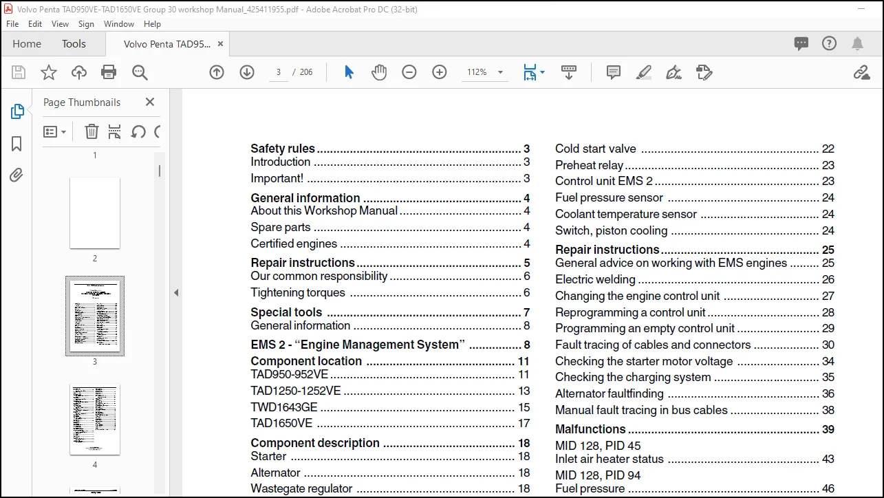
Safety rules …………………………………………………….. 3
Introduction ……………………………………………………… 3
Important! ……………………………………………………….. 3
General information ………………………………………… 4
About this Workshop Manual ………………………………. 4
Spare parts ……………………………………………………… 4
Certified engines ………………………………………………. 4
Repair instructions………………………………………….. 5
Our common responsibility …………………………………. 6
Tightening torques ……………………………………………. 6
Special tools ………………………………………………….. 7
General information …………………………………………… 8
EMS 2 – “Engine Management System” ……………. 8
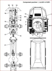
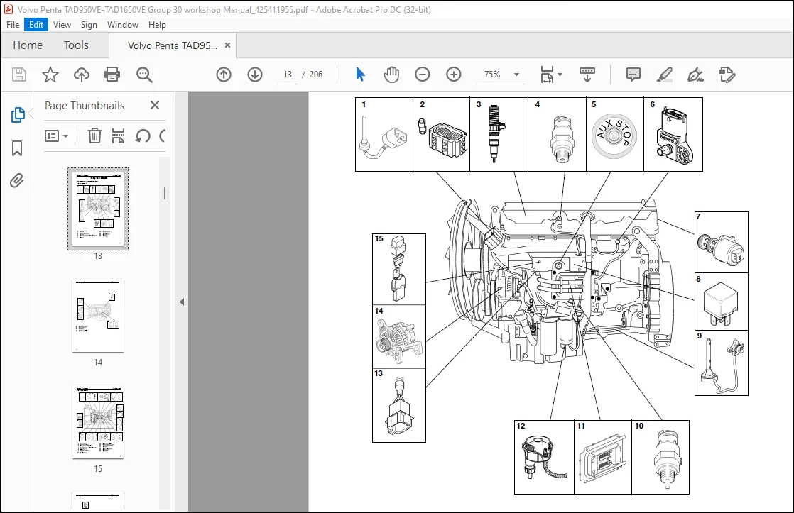
Component location ……………………………………… 11
TAD950-952VE……………………………………………….. 11
TAD1250-1252VE ……………………………………………. 13
TWD1643GE ………………………………………………….. 15
TAD1650VE …………………………………………………… 17
Component description …………………………………. 18
Starter ………………………………………………………….. 18
Alternator ………………………………………………………. 18
Wastegate regulator ………………………………………… 18
Speed sensor, crankshaft ………………………………… 19
Speed sensor, camshaft ………………………………….. 19
Unit injector ……………………………………………………. 19
Air inlet pressure/intake manifold
temperature sensor …………………………………………. 20
Oil pressure sensor …………………………………………. 20
EGR……………………………………………………………… 20
Oil level/temperature sensor …………………………….. 21
Air filter pressure/temperature sensor…………………. 21
Crankcase pressure sensor ………………………………. 21
Switch, water in fuel ………………………………………… 22
Exhaust temperature sensor …………………………….. 22
Switch, coolant level ……………………………………….. 22
Cold start valve ……………………………………………… 22
Preheat relay………………………………………………….. 23
Control unit EMS 2 ………………………………………….. 23
Fuel pressure sensor ………………………………………. 24
Coolant temperature sensor ……………………………… 24
Switch, piston cooling ……………………………………… 24
Repair instructions………………………………………… 25
General advice on working with EMS engines ……… 25
Electric welding ………………………………………………. 26
Changing the engine control unit ……………………….. 27
Reprogramming a control unit ……………………………. 28
Programming an empty control unit ……………………. 29
Fault tracing of cables and connectors ……………….. 30
Checking the starter motor voltage ……………………. 34
Checking the charging system ………………………….. 35
Alternator faultfinding ………………………………………. 36
Manual fault tracing in bus cables ……………………… 38
Malfunctions …………………………………………………. 39
MID 128, PID 45
Inlet air heater status ………………………………………. 43
MID 128, PID 94
Fuel pressure …………………………………………………. 46
Check fuel pressure sensor …………………………. 51
MID 128, PID 97
Water in fuel …………………………………………………… 52
Check water in fuel switch ………………………….. 55
MID 128, PID 98
Oil level …………………………………………………………. 56
Check oil level sensor …………………………………. 58
MID 128, PID 100
Oil pressure …………………………………………………… 60
Check oil pressure sensor ……………………………. 64
MID 128, PID 105
Intake manifold temperature ……………………………… 65
Check intake manifold temperature sensor …. 70
MID 128, PID 106
Air inlet pressure …………………………………………….. 71
Check air inlet pressure sensor …………………. 76
MID 128, SID 32
Wastegate output driver …………………………………. 161
MID 128, SID 70
Air inlet heater driver ……………………………………… 166
MID 128, SID 211
5V supply 2 ………………………………………………….. 169
MID 128/144, SID 231
Communication fault J 1939 ……………………………. 171
Check CAN bus cable. …………………………… 173
MID 128, SID 232
5 V supply 1 …………………………………………………. 175
MID 128, SID 240
Program memory fault ……………………………………. 177
MID 128, SID 250
Communication fault J1587/J1708 …………………… 178
MID 128/144, SID 253
Calibration memory, EEPROM, fault ………………… 180
MID 128/144, SID 254
Controller error ……………………………………………… 181
MID 128, PSID 201 ……………………………………….. 183
J1939 communication bus ……………………………… 183
No faultcode ……………………………………………….. 186
Fuel bleeding pump
(only TAD950-952VE) …………………………………….. 186
Engine protection ……………………………………….. 187
TAD950-952VE, TAD1250-1252VE …………………… 187
TWD1643GE ………………………………………………… 188
TAD1650VE …………………………………………………. 189
Wiring diagrams………………………………………….. 190
TAD950-952VE……………………………………………… 190
TAD1250-1252VE ………………………………………….. 191
TWD1643GE ………………………………………………… 192
TAD1650VE …………………………………………………. 193
Wiring diagram DCU ………………………………………. 194
Wiring diagram CIU ……………………………………….. 195
Technical data …………………………………………….. 196
Index ………………………………………………………….. 198
References to Service Bulletins ……………………. 200
MID 128, PID 107
Air filter pressure …………………………………………….. 77
Check air pressure switch ………………………… 81
MID 128, PID 108 …………………………………………… 82
Ambient air pressure ……………………………………….. 82
MID 128, PID 110
Coolant temperature ………………………………………… 83
Check coolant temperature sensor …………….. 90
MID 128, PID 111
Coolant level ………………………………………………….. 91
Check coolant level switch ……………………… 94
MID 128, PID 153
Crankcase pressure ………………………………………… 95
Check crankcase pressure sensor ………….. 100
MID 128, PID 158
Battery voltage ……………………………………………… 101
MID 128, PID 172
Inlet air temperature ………………………………………. 103
Check air inlet temperature sensor …………… 109
MID 128, PID 173 …………………………………………. 110
Exhaust temperature ……………………………………… 110
Check exhaust temperature sensor ………….. 113
MID 128, PID 175
Oil temperature …………………………………………….. 114
Check oil temperature sensor …………………. 118
MID 128, PID 190
Engine speed ……………………………………………….. 119
MID 128, PPID 3
Starter output failure ……………………………………… 120
Check starter motor relay. ………………………. 123
MID 128/144, PPID 4
Start input failure ………………………………………….. 124
MID 128, PPID 6
Stop input ……………………………………………………. 126
MID 128, PPID 8
Piston cooling pressure ………………………………….. 128
MID 128, PPID 19
Internal EGR status ………………………………………. 131
MID 128, PPID 98
Engine sync acknowledge ………………………………. 136
MID 128 / 144, PPID 132
Throttle input request failure, DCU/CIU …………….. 137
Logg throttle signal with Vodia …………………. 140
MID 128, PPID 332
Thermostat ………………………………………………….. 141
MID 128, SID 1-6
Unit injector # 1-6 ………………………………………….. 145
MID 128, SID 21
Speed sensor, camshaft ………………………………… 151
Check camshaft sensor …………………………. 155
MID 128, SID 22
Speed sensor, crankshaft ………………………………. 156
Check crankshaft sensor ……………………….. 160
Questions? Email us: [email protected]
https://vimeo.com/800267352
PLEASE NOTE:
- This is the same manual used by the dealers to diagnose and troubleshoot your vehicle
- You will be directed to the download page as soon as the purchase is completed. The whole payment and downloading process will take anywhere between 2-5 minutes
- Need any other service / repair / parts manual, please feel free to contact [email protected] . We still have 50,000 manuals unlisted
S.V