VRF High Efficiency Heat Pump Service Manual PDF
Original price was: $95.00.$19.95Current price is: $19.95.
Complete VRF service manual for high-efficiency high-ambient heat pump systems using R410A refrigerant. Covers 8HP to 72HP capacity range with full DC inverter technology. Comprehensive technical documentation including specifications, wiring diagrams, piping layouts, capacity tables, installation procedures, PCB settings, control functions, troubleshooting, and failure codes. Features backup running capability, optimal temperature control, and multi-module combinations for commercial applications.
Description
VRF High Efficiency Heat Pump Service Manual R410A Amazon System 8-72HP PDF DOWNLOAD
DESCRIPTION
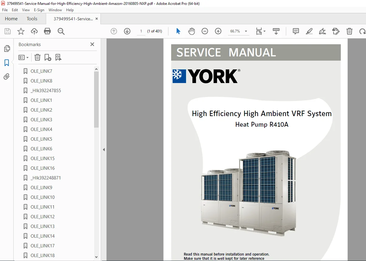
High Efficiency High Ambient VRF Heat Pump Complete Service Manual
This comprehensive professional service manual provides complete technical documentation for high-efficiency VRF (Variable Refrigerant Flow) heat pump systems featuring advanced DC inverter technology and high-ambient operation capabilities. Essential reference for HVAC contractors, service technicians, and building maintenance engineers working with large-scale commercial air conditioning installations.
📋 FILE DETAILS
| Specification | Details |
|---|---|
| Manual Name | High Efficiency High Ambient VRF System Service Manual |
| System Type | Heat Pump with R410A Refrigerant |
| Capacity Range | 8HP to 72HP (25-168 kW cooling) |
| Release Date | August 2016 |
| Pages | 401 pages |
| PDF Quality | High-resolution technical documentation with detailed diagrams |
| File Size | 20.4 MB |
| Format | A4 size professional layout |
📖 COMPREHENSIVE MANUAL CONTENTS
1. GENERAL INFORMATION
1.1 Advanced Features:
Full DC Inverter Technology – High Efficiency:
- ✓ DC fan motor – 40% efficiency enhancement
- ✓ Full DC inverter scroll compressor – 5% efficiency boost
- ✓ 180° vector inverter – 5% additional efficiency
- ✓ Zigzag fan design – Reduced air vibration
- ✓ Two-piece condenser – Two-stage sub-cooling with added sub-cooler
High Reliability Features:
- Backup Running Capability:
- Available in combination systems
- Single module backup (dual compressor units)
- Different compressor backup in same system
- Inter-system backup operation
- Extended Compressor Life:
- Recycling operation mode
- 2-stage oil separator system
- Double compressor protection
Compressor Protection Systems:
- Base air discharge temperature sensor
- Oil temperature sensor at compressor bottom
- Functions:
- Heater on/off control (prevents liquid shock)
- Liquid refrigerant detection
- Oil sub-heating protection
Lightning/Thunder Protection:
- Electrical discharge wires in terminal block
- Abnormal voltage earth grounding
- Surge protection design
Optimal Temperature Control:
- Indoor coil temperature monitoring
- Precise refrigerant amount control
- Compensation for piping length differences
- Individual indoor unit capacity adjustment
Easy Installation Features:
- Largest Capacity: Single module up to 24HP
- Maximum Combination: 3 modules = 72HP total
- Compact Footprint: Uniform 0.97㎡ bottom size
- Space Saving: 72HP system only 2.92㎡ (50% size reduction)
- High ESP: Up to 82 Pa outdoor static pressure for extended ductwork
1.2 Product Lineup: Complete model range from 8HP to 72HP with detailed specifications
2. SPECIFICATIONS (28 pages)
Complete Technical Data for All Models:
Model Range Covered:
- YV2VYH025KASFDA1 through YV2VYH168KASFDA1
- Single module: 8HP to 20HP capacity
- Combination systems: Up to 72HP
Key Specifications for Each Model:
- Cooling capacity (kW)
- Heating capacity (kW)
- Power supply requirements (3-phase, 380V, 50/60Hz)
- Maximum indoor units connected
- Electrical ratings
- Current draw specifications
- Operating voltage ranges
- Sound pressure levels
- Refrigerant charge quantities
Performance Data:
- COP (Coefficient of Performance)
- EER (Energy Efficiency Ratio)
- IPLV (Integrated Part Load Value)
- Part-load efficiency curves
3. DIMENSIONS (2 pages)
- Detailed dimensional drawings
- Outdoor unit measurements
- Clearance requirements
- Service access specifications
- Mounting dimensions
- Connection point locations
4. PIPING DIAGRAM (3 pages)
Refrigerant Circuit Schematics:
- Complete piping layouts
- Refrigerant flow patterns
- Component locations
- Valve positions
- Connection points
- Pipe sizing requirements
5. WIRING DIAGRAM (1 page)
- Complete electrical schematics
- Power distribution
- Control wiring
- Communication lines
- Safety circuits
- Grounding diagrams
6. CAPACITY CALCULATION & MODIFICATION COEFFICIENT (9 pages)
Capacity Adjustment Factors:
- Piping length correction factors
- Elevation difference coefficients
- Indoor/outdoor unit combination ratios
- Temperature correction factors
- Installation configuration adjustments
- Multi-module combination calculations
7. OPERATION RANGE (1 page)
- Cooling mode temperature ranges
- Heating mode temperature ranges
- High-ambient operation limits
- Low-ambient operation capabilities
- Humidity operating ranges
8. NOISE LEVEL (3 pages)
- Sound pressure measurements
- Sound power levels
- Frequency analysis
- Operating mode noise data
- Distance attenuation charts
9. OUTDOOR COOLING CAPACITY TABLE (81 pages)
Extensive Capacity Data:
- Capacity at various outdoor temperatures
- Indoor temperature variations
- Part-load capacity tables
- Wet bulb/dry bulb combinations
- Performance curves
- Derating factors
10. OUTDOOR HEATING CAPACITY TABLE (135 pages)
Comprehensive Heating Performance:
- Heating capacity at different outdoor temperatures
- Indoor setpoint variations
- Defrost cycle considerations
- Low-ambient heating performance
- Heat pump operation limits
- Supplemental heat requirements
11. INSTALLATION (29 pages)
Complete Installation Procedures:
Site Preparation:
- Location selection criteria
- Foundation requirements
- Clearance specifications
- Ventilation requirements
Mechanical Installation:
- Unit positioning and leveling
- Piping connections
- Refrigerant piping guidelines
- Condensate drainage
- Insulation requirements
Electrical Installation:
- Power supply connections
- Control wiring procedures
- Communication line installation
- Grounding requirements
- Safety disconnect installation
Refrigerant System:
- Evacuation procedures
- Leak testing methods
- Refrigerant charging procedures
- System pressure checks
12. MANIFOLD PIPE DIMENSION (2 pages)
- Header pipe sizing
- Branch connection specifications
- Joint configurations
- Pressure drop calculations
13. BRANCH PIPE DIMENSION (1 page)
- Individual branch sizing
- Connection methods
- Distributor specifications
14. TRIAL OPERATION (9 pages)
Commissioning Procedures:
- Pre-startup checklist
- Initial power-up sequence
- System configuration verification
- Test run procedures
- Performance verification
- Adjustment procedures
- Customer acceptance testing
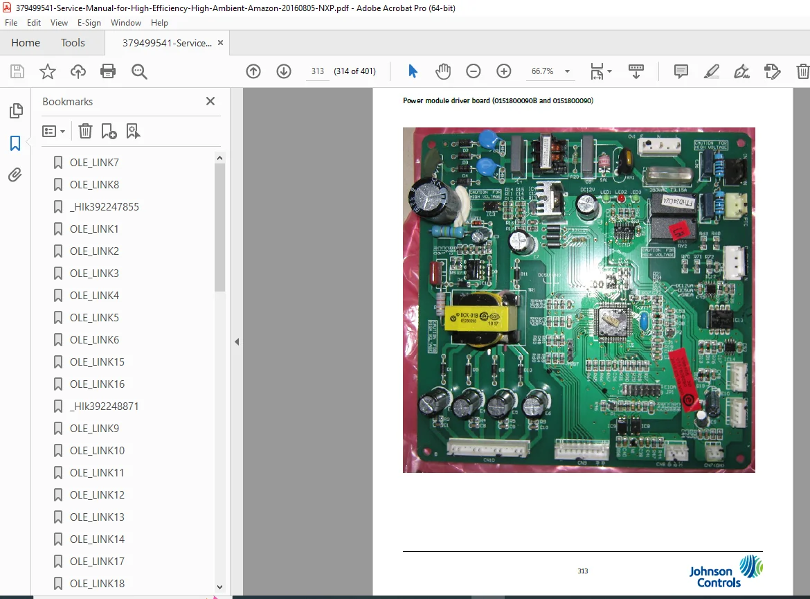
15. OUTDOOR CONTROL BOARD PHOTO (4 pages)
- PCB component identification
- LED indicator locations
- Terminal block layouts
- Connector descriptions
- Test point locations
16. OUTDOOR PCB DIP SWITCH SETTING (11 pages)
Configuration Settings:
- DIP switch function chart
- Address setting procedures
- System configuration options
- Feature enable/disable
- Communication settings
- Master/slave designation
- Combination system setup
17. OUTDOOR SYSTEM CONTROL FUNCTION (6 pages)
Control Logic:
- Capacity control algorithms
- Temperature control sequences
- Defrost control operation
- Oil return control
- Protection control logic
- Load balancing
- Energy optimization
18. FAILURE CODE (7 pages)
Complete Error Code Reference:
- Error code listings
- Fault descriptions
- LED display patterns
- Diagnostic procedures
- Troubleshooting flowcharts
Common Error Codes:
- Compressor faults
- Sensor errors
- Communication failures
- Refrigerant system issues
- Electrical problems
- Temperature abnormalities
19. TROUBLESHOOTING (50 pages)
Comprehensive Diagnostic Guide:
Systematic Troubleshooting:
- Symptom-based diagnostics
- Component testing procedures
- Electrical measurements
- Refrigerant system checks
- Control system verification
Problem Categories:
- No operation issues
- Insufficient cooling/heating
- Compressor problems
- Fan motor failures
- Control board malfunctions
- Sensor failures
- Refrigerant leaks
- Communication errors
Testing Procedures:
- Voltage measurements
- Current draw verification
- Resistance checks
- Pressure readings
- Temperature measurements
- Signal testing
APPENDIX (12 pages)
- Additional technical data
- Conversion charts
- Reference tables
- Maintenance schedules
- Service bulletins
- Update information
🔧 MODELS COVERED
Single Module Units (8-24HP):
- YV2VYH025KASFDA1 (25.42 kW cooling / 28.08 kW heating)
- YV2VYH028KASFDA1 (28.90 kW / 33.80 kW)
- YV2VYH033KASFDA1 (34.80 kW / 37.90 kW)
- YV2VYH040KASFDA1 (41.50 kW / 45.80 kW)
- YV2VYH045KASFDA1 (46.40 kW / 51.10 kW)
- YV2VYH050KASFDA1 through YV2VYH168KASFDA1
Combination Systems:
- 2-module combinations
- 3-module combinations (up to 72HP)
- Mixed capacity combinations
- System matching requirements
💡 ADVANCED TECHNOLOGY FEATURES
DC Inverter Technology:
- Variable speed compressor control
- Precise capacity modulation
- Energy efficiency optimization
- Smooth operation
- Reduced power consumption
High Ambient Operation:
- Extended outdoor temperature range
- Enhanced condenser design
- High-pressure protection
- Optimized refrigerant flow
Multi-Module Control:
- Master/slave configuration
- Load distribution
- Balanced operation
- System redundancy
- Backup operation modes
👥 ESSENTIAL FOR HVAC PROFESSIONALS
This manual is critical for:
- HVAC Service Technicians installing and maintaining VRF systems
- Commercial HVAC Contractors designing large installations
- Building Maintenance Engineers managing facility equipment
- Mechanical Engineers specifying HVAC systems
- Technical Support Personnel providing remote assistance
- Training Instructors teaching VRF technology
- Facility Managers overseeing commercial buildings
🏢 COMMERCIAL APPLICATIONS
Ideal for:
- Office buildings
- Hotels and resorts
- Shopping centers
- Hospitals and healthcare facilities
- Educational institutions
- Data centers
- Manufacturing facilities
- High-rise residential buildings
⚙️ SYSTEM CAPABILITIES
Capacity Range:
- Single outdoor: 8HP to 24HP
- Maximum combination: 72HP
- Indoor units: Up to 64 units per system
- Piping length: Extended distance capability
- Elevation difference: High-rise capability
Operating Modes:
- Cooling mode
- Heating mode
- Auto changeover
- Simultaneous cooling/heating (with heat recovery)
🛠️ INSTALLATION HIGHLIGHTS
Piping Requirements:
- R410A compatible materials
- Proper sizing calculations
- Branch selection guides
- Insulation specifications
- Pressure testing procedures
Electrical Requirements:
- 3-phase 380V power supply
- Proper wire sizing
- Circuit protection
- Control voltage wiring
- Communication cabling
🔍 DIAGNOSTIC TOOLS
Service Features:
- PCB-mounted LED indicators
- DIP switch diagnostic modes
- Test operation functions
- Parameter monitoring
- Error history logging
- Real-time status display
📊 CAPACITY TABLES
Performance Data:
- 81 pages of cooling capacity tables
- 135 pages of heating capacity tables
- Multiple operating conditions
- Part-load performance
- Combination system ratings
⚡ EFFICIENCY FEATURES
Energy Savings:
- High COP/EER ratings
- Part-load optimization
- Variable speed operation
- Intelligent defrost control
- Low-load operation capability
⚡ INSTANT DOWNLOAD – INSTALL & SERVICE VRF SYSTEMS TODAY! This comprehensive 401-page technical manual provides complete documentation for high-efficiency VRF heat pump installations from 8HP to 72HP capacity. With extensive capacity tables, detailed wiring and piping diagrams, complete troubleshooting guides, and professional installation procedures, you’ll have factory-level expertise at your fingertips. Download immediately and master advanced VRF technology for commercial HVAC applications!
Pricing Rationale:
- 401 pages of highly technical content
- Covers extensive model range (8-72HP capacity)
- 81 pages of cooling capacity tables
- 135 pages of heating capacity tables
- Commercial/industrial VRF systems
- Advanced DC inverter technology
- Multi-module system configurations
- Critical for large-scale installations
- Professional HVAC contractor resource
- High-value commercial equipment documentation