Trusted Business
Verified & Licensed
Virus Free Files
100% Safe Downloads
Secure Payment
SSL Protected
Instant Delivery
Available Immediately
Sale!


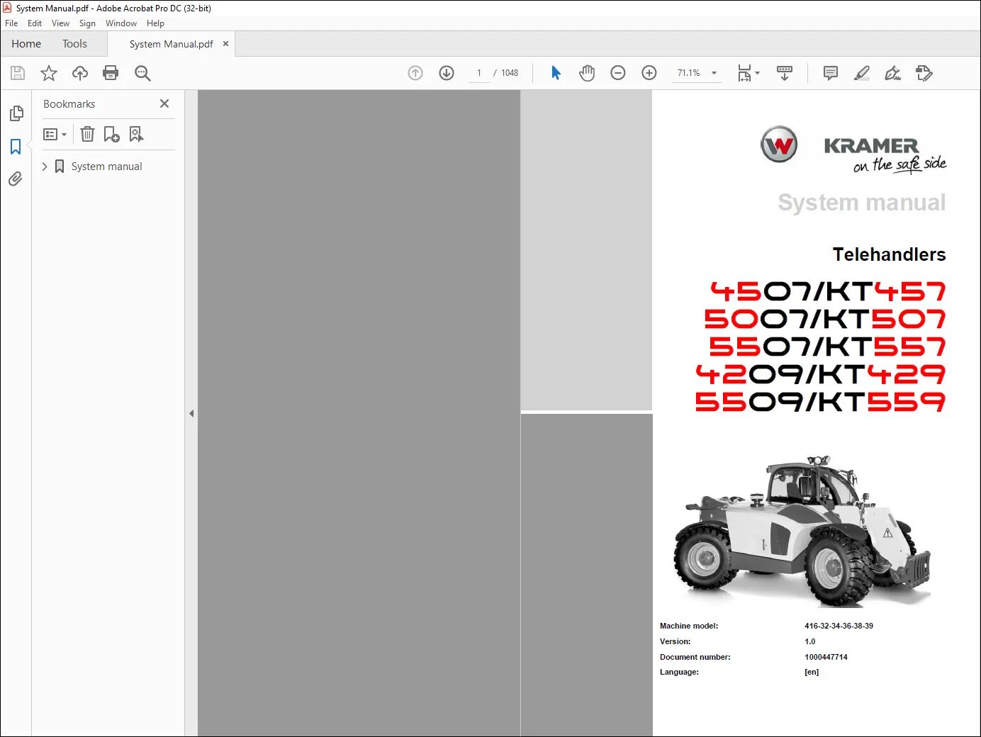
Wacker Kramer 4507/KT457 5007/KT507 5507/KT557 4209/KT429 5509/KT559 Telehandlers System manual- PDF DOWNLOAD
Original price was: $80.00.$38.95Current price is: $38.95.
Wacker Kramer 4507/KT457 5007/KT507 5507/KT557 4209/KT429 5509/KT559 Telehandlers System manual- PDF DOWNLOAD
Instant PDF Download
Available immediately
Save to Your Device
Download & keep forever
Antivirus Scanned
100% virus-free
Trusted Worldwide
175,000+ customers
Description
Wacker Kramer 4507/KT457 5007/KT507 5507/KT557 4209/KT429 5509/KT559 Telehandlers System manual- PDF DOWNLOAD
FILE DETAILS:
Wacker Kramer 4507/KT457 5007/KT507 5507/KT557 4209/KT429 5509/KT559 Telehandlers System manual- PDF DOWNLOAD
Language :English
Pages :1048
Downloadable : Yes
File Type : PDF
Size:53.4 MB
IMAGES PREVIEW OF THE MANUAL:
TABLE OF CONTENTS:
Wacker Kramer 4507/KT457 5007/KT507 5507/KT557 4209/KT429 5509/KT559 Telehandlers System manual- PDF DOWNLOAD
System manual............................................................................................................................   1
	E Introduction.......................................................................................................................   3
		E.1 Notes on system manual.......................................................................................................   4
			Use of the system manual.....................................................................................................   4
			Required tools and screw connections.........................................................................................   5
			Procedure....................................................................................................................   5
		E.2 Safety instructions..........................................................................................................   6
			Pay particular attention to the following....................................................................................   6
			Safety symbols and signal words..............................................................................................   6
			Safety and accident prevention regulations...................................................................................   7
		E.3 Symbol and abbreviations.....................................................................................................  11
			Symbols......................................................................................................................  11
			Abbreviations................................................................................................................  12
		E.4 Tightening torques...........................................................................................................  15
			General tightening torques...................................................................................................  15
			Torque values for metric coarse-pitch thread.................................................................................  16
			Torque values for metric fine-pitch thread...................................................................................  17
			Tightening torques for hydraulic screw connections and climate screw fixtures with taper connections and O-rings DIN 3865....  18
			Tightening torques for hydraulic screw connections with cutting ring DIN 3861................................................  19
			Tightening torques for hydraulic screw struts SDS............................................................................  20
			Tightening torques for hydraulics rotating screw connections.................................................................  23
			Tightening torques for hollow screws DIN 7643................................................................................  23
			Tightening torques for hydraulic system screw-in spuds SDE...................................................................  24
			Tightening torques for brake line screw connections..........................................................................  26
			Tightening torques for worm drive hose clamps................................................................................  26
			Tightening torques for spring-loaded worm drive hose clamps..................................................................  26
	2 Engine.............................................................................................................................  27
		2.1 Overview of components TCD 3.6...............................................................................................  28
			Technical data...............................................................................................................  28
			Type plates for TCD 3.6......................................................................................................  29
			Cylinder numbering...........................................................................................................  30
			Overview of diesel engine from right TCD 3.6.................................................................................  31
			Overview of diesel engine from left TCD 3.6..................................................................................  32
		2.2 Lubricant oil system TCD 3.6.................................................................................................  33
			Component overview of the lubricating oil system.............................................................................  33
			Lube oil circuit.............................................................................................................  34
			Oil pressure control valve...................................................................................................  36
			Pressure limiting valve......................................................................................................  37
		2.3 Fuel system TCD 3.6..........................................................................................................  38
			Component overview of the fuel system........................................................................................  38
			Fuel injection system........................................................................................................  41
			Injector.....................................................................................................................  42
			High-pressure pump...........................................................................................................  45
			Control valve Y076 (FCU).....................................................................................................  46
			Pressure relief valve for the rail (PRV).....................................................................................  47
		2.4 Cooling system TCD 3.6.......................................................................................................  48
			Cooling liquid inlet.........................................................................................................  48
			Thermostat overview..........................................................................................................  50
			Coolant drainage.............................................................................................................  51
		2.5 Turbocharging TCD 3.6........................................................................................................  52
			Turbo-charging...............................................................................................................  52
		2.6 Exhaust gas recirculation EGR TCD 3.6........................................................................................  53
			Exhaust gas recirculation cooler (EGR cooler)................................................................................  54
			Adjustment valve of the EGR exhaust gas recirculation........................................................................  55
			Reed valve of the EGR exhaust gas recirculation..............................................................................  56
		2.7 Electric components TCD 3.6..................................................................................................  57
		2.8 Overview of components TCD 4.1...............................................................................................  61
			Technical data...............................................................................................................  61
			Type labels diesel engine TCD 4.1............................................................................................  62
			Cylinder numbering...........................................................................................................  63
			Overview of diesel engine from right TCD 4.1.................................................................................  64
			Overview of diesel engine from left TCD 4.1..................................................................................  65
		2.9 Lubricant oil system TCD 4.1.................................................................................................  66
		2.10 Fuel system TCD 4.1.........................................................................................................  68
			Fuel injection system........................................................................................................  70
			Injector.....................................................................................................................  71
			Pressure relief valve for the rail (PRV).....................................................................................  73
			Metering unit (FCU)..........................................................................................................  74
			Metering unit (FCU)..........................................................................................................  75
			High-pressure pump...........................................................................................................  76
			Operation of the high pressure pumps.........................................................................................  77
			Operation of the high pressure pumps.........................................................................................  78
		2.11 Cooling circuit TCD 4.1.....................................................................................................  79
			Checking the thermostat......................................................................................................  81
			Coolant drainage.............................................................................................................  82
		2.12 Turbocharging TCD4.1........................................................................................................  83
			Overview of turbocharging....................................................................................................  84
		2.13 Exhaust gas recirculation EGR TCD 4.1.......................................................................................  85
			Regulating unit (EGR valve) exhaust gas recirculation........................................................................  87
			Exhaust gas recirculation cooler (EGR cooler)................................................................................  88
			Reed valve of the EGR exhaust gas recirculation..............................................................................  89
		2.14 Electric components TCD 4.1.................................................................................................  90
			Electric components of diesel engine.........................................................................................  91
		2.15 Exhaust-gas treatment.......................................................................................................  92
			General information on emissions legislation.................................................................................  92
			Abbreviations................................................................................................................  93
			Explanation of terms.........................................................................................................  94
			Exhaust after-treatment system EAT...........................................................................................  95
			Overview of the exhaust aftertreatment.......................................................................................  96
			Electrical components of exhaust aftertreatment..............................................................................  97
			Exhaust aftertreatment disconnect XM05.......................................................................................  98
			CSF system setup............................................................................................................. 100
			SCR catalytic converter...................................................................................................... 101
			Mixing section............................................................................................................... 103
			Metering unit Y141........................................................................................................... 104
			Differential pressure sensor B037............................................................................................ 106
			Exhaust back pressure sensor B092............................................................................................ 108
			Temperature sensor B029/B030/B090............................................................................................ 109
			NOXsensor and NOX electronics B093/B094...................................................................................... 111
			Urea provision............................................................................................................... 113
			Urea fill level indicator H094/H095.......................................................................................... 114
			Ambient temperature sensor B031.............................................................................................. 115
			Sampling unit B095........................................................................................................... 116
			Discharge module............................................................................................................. 118
			Solenoid valve for the tank heater Y143...................................................................................... 120
		2.16 Exhaust system only for EDG................................................................................................. 121
		2.17 Starting the engine......................................................................................................... 122
			Start diesel engine control.................................................................................................. 122
			Start diesel engine activation with drive interlock.......................................................................... 123
			Description of starting engine............................................................................................... 124
		2.18 Diesel engine monitoring.................................................................................................... 125
		2.19 Diesel engine monitoring components......................................................................................... 126
		2.20 Control of EAT system....................................................................................................... 128
			Urea injection............................................................................................................... 128
			Description of EAT system components......................................................................................... 129
		2.21 Heating circuit of EAT system............................................................................................... 130
			Heating circuit of diesel engine 3.6 EAT system.............................................................................. 130
			Heating circuit of diesel engine 4.1 EAT system.............................................................................. 131
			Description of heating circuit components.................................................................................... 132
	3 Cooling............................................................................................................................ 133
		3.1 Cooling control.............................................................................................................. 134
			Cooling control - standard................................................................................................... 134
			Cooling control - standard + trailer brake................................................................................... 135
			Control of the cooling reversing fan......................................................................................... 136
			Cooling reversing fan control + trailer brake................................................................................ 137
		3.2 Components of the component control.......................................................................................... 138
			Cooling description - standard............................................................................................... 138
			Cooling description - standard + trailer brake............................................................................... 139
			Description of the cooling reversing fan..................................................................................... 140
			Description of the cooling reversing fan + trailer brake..................................................................... 141
		3.3 Functional description of cooling components................................................................................. 142
			Fan control.................................................................................................................. 142
			Fan speed.................................................................................................................... 142
			Hydraulic oil temperature gauge.............................................................................................. 142
			Coolant temperature display.................................................................................................. 142
			Reversing operation.......................................................................................................... 143
		3.4 Cooling component description................................................................................................ 144
			Tandem pump 001.1............................................................................................................ 145
			Fan motor II................................................................................................................. 146
			Reversing valve for fan XXIII................................................................................................ 147
			Fan valve, standard XXIV..................................................................................................... 148
			Coolant level sensor B015.................................................................................................... 149
			Fan control temperature sensor B016.......................................................................................... 149
		3.5 Check / adjust cooling....................................................................................................... 150
			Checking and making adjustments.............................................................................................. 150
			Test report: cooling......................................................................................................... 151
			Checking the diesel engine speed............................................................................................. 152
			Checking / adjusting the fan speed........................................................................................... 153
	4 Traveling drive.................................................................................................................... 155
		4.1 Drive control................................................................................................................ 156
			Control of drive system with high speed transmission (ICVD).................................................................. 156
			Control of the high-speed transmission drive system P370..................................................................... 157
			Description of drive control................................................................................................. 158
		4.2 Function description of travelling drive..................................................................................... 160
			Forward travel............................................................................................................... 160
			Reverse travel............................................................................................................... 161
			Boost pressure............................................................................................................... 162
			Inching function............................................................................................................. 162
			Low-speed control............................................................................................................ 162
			Speed ranges................................................................................................................. 162
			Travel speeds................................................................................................................ 163
		4.3 Drive component description.................................................................................................. 164
			Speed sensor B009............................................................................................................ 165
			1st/2nd speed proportional valve Y002........................................................................................ 166
			Proportional valves Y004/Y005................................................................................................ 168
			Driving direction identification solenoid valve Y010......................................................................... 169
			PCOR valve Y112 depending on the degree of utilization....................................................................... 170
		4.4 Drive system with H1P and ICVD............................................................................................... 172
			Overview of variable displacement pump VII (H1P089).......................................................................... 172
			Overview of high-speed transmission X (ICVD)................................................................................. 174
			Control cover................................................................................................................ 175
			Setting the high-speed gearbox............................................................................................... 176
			Stroke adjustment............................................................................................................ 178
			Pressure limiting valve (PCOR) for control piston M3......................................................................... 179
			Driving direction identification 058......................................................................................... 180
			Scouring slide valve 059..................................................................................................... 181
			Gear unit.................................................................................................................... 182
		4.5 Checking / adjusting ICVD high speed gearbox................................................................................. 183
			Checking and making adjustments.............................................................................................. 183
			Test report: model 416-32 (i=1.18:1)......................................................................................... 185
			Test report: model 416-32 (i=1.18:1)......................................................................................... 188
			Test report: model 416-32 /416-38 / 416-39 (i=1.39:1)........................................................................ 190
			Test report: model 416-32 /416-38 / 416-39 (i=1.39:1)........................................................................ 192
			Test port fittings for high-speed gearbox.................................................................................... 194
			Checking the diesel engine speed............................................................................................. 195
			Checking / adjusting boost pressure.......................................................................................... 196
			Checking / adjusting starting speed.......................................................................................... 197
			Driving direction identification: Checking................................................................................... 198
			Checking/setting the pressure cut-off (H1P089)............................................................................... 199
			Check high pressure.......................................................................................................... 201
			Checking / adjusting cardan shaft speed...................................................................................... 203
			Checking / adjusting engine lugging, variable displacement pump VII.......................................................... 204
			Checking / adjusting engine droop, high speed gearbox X...................................................................... 205
		4.6 Error descriptions........................................................................................................... 206
			Boost pressure not attained.................................................................................................. 206
			High pressure not attained................................................................................................... 206
			Starting speed............................................................................................................... 207
			The vehicle does not reach the final speed................................................................................... 207
			Vehicle only drives in Snail mode............................................................................................ 208
			Drive has no output.......................................................................................................... 208
			Vehicle cannot drive forwards or backwards................................................................................... 209
			Check scouring slide 059..................................................................................................... 210
			Check forward-reverse spool valve 058........................................................................................ 211
			Check proportional controller 100............................................................................................ 213
		4.7 Drive system with H1P and P370............................................................................................... 214
			Hydraulic pump VII........................................................................................................... 214
			Overview of hydraulic pump VII............................................................................................... 215
			Overview of high-speed transmission X (P370)................................................................................. 217
			Cam cover P370............................................................................................................... 218
			Scouring slide valve 059..................................................................................................... 219
			Gear unit.................................................................................................................... 220
		4.8 Adjustment work for drive system............................................................................................. 221
			Test report: model 416-34 / 416-36........................................................................................... 222
			Test report: model 416-34 / 416-36........................................................................................... 225
			Test report: model 416-34 / 416-36........................................................................................... 227
			Test report: model 416-34 / 416-36........................................................................................... 229
			Test report: model 416-32 / 416-38 / 416-39.................................................................................. 231
			Test report: model 416-32 / 416-38 / 416-39.................................................................................. 234
			Drive test ports............................................................................................................. 236
			Checking the diesel engine speed............................................................................................. 237
			Setting the boost pressure................................................................................................... 238
			Adjusting starting engine speed.............................................................................................. 239
			Driving direction identification: Checking................................................................................... 240
			Check and adjust the pressure cut-off........................................................................................ 241
			Check high pressure.......................................................................................................... 243
			If the high pressure is not attained......................................................................................... 244
			Checking / adjusting cardan shaft speed...................................................................................... 245
			Checking / adjusting engine droop, variable displacement pump VII............................................................ 246
			Checking / adjusting engine droop, high speed gearbox X...................................................................... 247
		4.9 Error descriptions........................................................................................................... 248
			Boost pressure not attained.................................................................................................. 248
			High pressure not attained................................................................................................... 248
			Starting speed............................................................................................................... 249
			The vehicle does not reach the final speed................................................................................... 249
			Vehicle only drives in Snail mode............................................................................................ 250
			Drive has no output.......................................................................................................... 250
			Vehicle cannot drive forwards or backwards................................................................................... 250
			Check scouring slide 059..................................................................................................... 251
			Check travel direction slide 058 (Y010)...................................................................................... 252
			Check the PCOR Y112 dependent on electric degree of utilization.............................................................. 253
			Check solenoid valve for speed Y002.......................................................................................... 254
	6 Brakes............................................................................................................................. 255
		6.1 Brake control................................................................................................................ 256
			Control of the vehicle brake................................................................................................. 256
			Control of the parking brake................................................................................................. 257
			Description of brake control................................................................................................. 258
			Description of parking brake control......................................................................................... 259
			Control of hydraulic trailer brake........................................................................................... 260
			Description of the hydraulic trailer brake actuation......................................................................... 261
		6.2 Trailer compressed air brake control......................................................................................... 262
			Compressed air brake control................................................................................................. 262
			Electric compressed air braking system control............................................................................... 263
			Compressed air brake diagram................................................................................................. 264
			Compressed air brake description............................................................................................. 265
		6.3 Functional description of the braking system components...................................................................... 266
			Service brake................................................................................................................ 266
			Brake/inching pedal (service brake).......................................................................................... 268
			Parking brake................................................................................................................ 270
			Hydraulic trailer brake...................................................................................................... 273
			Compressed-air braking system................................................................................................ 276
		6.4 Description of brake system elements......................................................................................... 281
			Tandem pump 001.1............................................................................................................ 282
			Pressure accumulator charge valve XIX........................................................................................ 283
			Brake valve XVIII with inching potentiometer R002............................................................................ 284
			Hydraulic trailer brake valve 140............................................................................................ 285
			Pressure accumulator 142 (R1, R2)............................................................................................ 292
			Valve block 162 (only for hydraulic trailer brakes).......................................................................... 294
			Power brake sensor B051...................................................................................................... 295
			Proportional valve trailer brake Y113........................................................................................ 296
			Solenoid valve of the trailer brake Y115..................................................................................... 297
			Brake light switching relay K030............................................................................................. 298
			Relay K055................................................................................................................... 299
			Inching position encoder R002................................................................................................ 300
			Button S065 parking brake.................................................................................................... 301
		6.5 Element description for the compressed air system............................................................................ 302
			Compressor P500.............................................................................................................. 302
			Pressure regulator 510....................................................................................................... 303
			Air reservoir 520............................................................................................................ 305
			Automatic drainage valve..................................................................................................... 306
			Pressure reducing valve P530................................................................................................. 307
			Solenoid valve for compressed-air brake, parking brake signal Y049........................................................... 309
			Solenoid valve, compressed-air brake advancement Y050........................................................................ 310
			Non-return valve P560........................................................................................................ 312
			Trailer control valve P570................................................................................................... 313
			Trailer control valve P571................................................................................................... 314
			Compressed air brake system sensor B052...................................................................................... 315
			Push button switch for the compressed air brake S208......................................................................... 316
			Touch button for compressed air brake S209................................................................................... 317
		6.6 Braking system test logs..................................................................................................... 318
			Checking and making adjustments.............................................................................................. 318
			Test report: service brake................................................................................................... 320
			Checking the diesel engine speed............................................................................................. 321
			Check the accumulator pressure............................................................................................... 322
			Checking / adjusting pilot control pressure.................................................................................. 323
			Check the brake pressure of the front axle service brake..................................................................... 324
			Brake pressure for the rear axle service brake............................................................................... 325
			Test the brake pressure for the parking brake................................................................................ 326
		6.7 Trailer brake test log....................................................................................................... 327
			Hydraulic trailer brake...................................................................................................... 327
			Connections for trailer brake................................................................................................ 328
		6.8 Compressed air brake system test log......................................................................................... 329
			Compressed-air brake......................................................................................................... 329
			Check service brake.......................................................................................................... 331
			Check the hand brake......................................................................................................... 332
			Test push-button............................................................................................................. 333
			Leak test.................................................................................................................... 334
			Check the break function..................................................................................................... 335
	7 Steering system.................................................................................................................... 336
		7.1 Steering system actuation.................................................................................................... 337
			Overview of Steering Control................................................................................................. 337
			Description of steering components........................................................................................... 338
		7.2 Function description: steering system........................................................................................ 339
			Steering system oil supply................................................................................................... 339
			Emergency steering function.................................................................................................. 339
			Steering mode valve with check block XXVII................................................................................... 339
			Steering electronics......................................................................................................... 339
			Synchronize the steering system after a repair............................................................................... 340
			Bleeding the steering system................................................................................................. 341
		7.3 Description of steering components........................................................................................... 342
			Double gear pump 001.1....................................................................................................... 343
			Hydrostatic steering system IV............................................................................................... 344
			Steering mode valve with check block XXVII................................................................................... 346
			Steering sensors B004 and B005............................................................................................... 349
			Switch S022 steering mode switch............................................................................................. 350
			Switch S022 steering mode switch (4 steering modes).......................................................................... 352
			Push button switch for steering pressure S217................................................................................ 354
		7.4 Check / adjust steering system............................................................................................... 355
			Checking and making adjustments.............................................................................................. 355
			Test report: steering system................................................................................................. 356
			Checking the diesel engine speed............................................................................................. 357
			Inspecting and adjusting the steering pressure............................................................................... 358
	8 Hydraulics......................................................................................................................... 359
		8.1 Lifting cylinder / load stabilizer actuation................................................................................. 360
			Overview of electrical control............................................................................................... 360
			Overview of hydraulic control................................................................................................ 361
			Description of lifting cylinder with load stabiliser......................................................................... 362
		8.2 Control of the overload control.............................................................................................. 364
			Overview of electrical control............................................................................................... 364
			Overview of hydraulic control................................................................................................ 365
			Description of the overload control.......................................................................................... 366
		8.3 Tilt ram control............................................................................................................. 368
			Overview of electrical control............................................................................................... 368
			Overview of hydraulic control................................................................................................ 369
			Description of tilt ram...................................................................................................... 370
		8.4 Bucket repositioning control................................................................................................. 371
			Overview of electrical control............................................................................................... 371
			Overview of hydraulic control................................................................................................ 372
			Description of bucket retraction............................................................................................. 373
		8.5 3rd control circuit (control)................................................................................................ 374
			Overview of electrical control............................................................................................... 374
			Overview of hydraulic control................................................................................................ 375
			Description of 3rd control circuit........................................................................................... 376
		8.6 Control of the 3rd control circuit with changeover valve..................................................................... 377
			Overview of electrical control............................................................................................... 377
			Overview of hydraulic control................................................................................................ 378
			Description of 3rd control circuit, changeover valve......................................................................... 379
		8.7 Tipper control............................................................................................................... 381
			Overview of electrical / hydraulic control................................................................................... 381
			Description of tipping trailer............................................................................................... 382
		8.8 Control of the tipper/auto-hitch............................................................................................. 383
			Overview of electrical control............................................................................................... 383
			Overview of hydraulic control................................................................................................ 384
			Description of the tipper/auto-hitch......................................................................................... 385
		8.9 Adjust the sensor plate sensor S137.......................................................................................... 386
			Overview of autohitch 092.................................................................................................... 387
			Adjusting the sensor plate................................................................................................... 388
			The sensor plate cannot be adjusted.......................................................................................... 389
		8.10 Rear additional control circuit actuation................................................................................... 391
			Overview of electrical/ hydraulic control.................................................................................... 391
			Description of rear additional control circuit............................................................................... 392
		8.11 Actuation of additional control circuit, large, front....................................................................... 393
			Overview of electrical/ hydraulic control.................................................................................... 393
			Description of additional control circuit, large, front...................................................................... 394
		8.12 Control of the leveling/oscillating-axle interlock model 416-36............................................................. 395
			Overview of electrical/ hydraulic control.................................................................................... 395
			Description of leveling / oscillating-axle interlock......................................................................... 396
		8.13 Control of the leveling and tipper model 416-36............................................................................. 397
			Overview of electrical control............................................................................................... 397
			Overview of hydraulic control................................................................................................ 398
			Description of the leveling and tipper....................................................................................... 399
		8.14 Control of the leveling, tipper, hitch model 416-36......................................................................... 400
			Overview of electrical control............................................................................................... 400
			Overview of hydraulic control................................................................................................ 401
			Description of the leveling, tipper, hitch................................................................................... 402
		8.15 Hydraulics component description............................................................................................ 404
			Tandem pump 001.1............................................................................................................ 405
			Boost pressure filter 015.................................................................................................... 406
			Reflux filter 026............................................................................................................ 407
			Hydraulic oil cooler 027..................................................................................................... 408
			Pressure accumulator 077 and 080............................................................................................. 409
			Suction valve for tipping compensation cylinder 082.......................................................................... 412
			Tilt ram hose burst valve 088................................................................................................ 413
			Hose burst valve level cylinder 088.......................................................................................... 415
			Hose burst valve for push-out ram 090........................................................................................ 417
			Quickhitch lock valve block 117.............................................................................................. 418
			Changeover valve for tipper/leveling 131..................................................................................... 419
			Changeover valve of 4th service 133.......................................................................................... 420
			Relief valve 134............................................................................................................. 422
			Valve block pressureless circulation 143..................................................................................... 423
			Bleed valve load stabilizer 144.............................................................................................. 424
			Valve block 162 (only for hydraulic trailer brakes).......................................................................... 425
			Pilot control valve 163...................................................................................................... 427
			Variable displacement pump for work hydraulics I............................................................................. 428
			Valve block V................................................................................................................ 431
			Hydraulic control unit XIII.................................................................................................. 433
			Connections of hydraulic control unit XIII model: 416-32-34-38............................................................... 434
			Secondary valves, model: 416-32-34-38........................................................................................ 435
			Connections of hydraulic control unit XIII model: 416-26/29.................................................................. 436
			Secondary valves model: 416-26/29............................................................................................ 437
			Connections for hydraulic control unit XII................................................................................... 438
			Hose burst valve with load stabilizer XIV.................................................................................... 439
			Pressure accumulator charge valve XIX........................................................................................ 441
			Hydraulic tank XX............................................................................................................ 442
			Intake filter................................................................................................................ 443
		8.16 Check / adjust work hydraulics.............................................................................................. 444
			Checking and making adjustments.............................................................................................. 444
			Test report for work hydraulics: Model 416-32-34-38.......................................................................... 445
			Test report for work hydraulics: Model 416-22-24-26-28-29.................................................................... 447
			Checking the diesel engine speed............................................................................................. 450
			Checking/adjusting the circuit pressure...................................................................................... 451
			Checking / adjusting the working pressure.................................................................................... 452
			Checking / adjusting the pressure regulator of the variable displacement pump I.............................................. 453
			Check the LS pressure........................................................................................................ 454
			Checking / adjusting pilot control pressure.................................................................................. 455
		8.17 Checking secondary valves................................................................................................... 456
			Check secondary valves, model: 416-32-34-38.................................................................................. 456
			Removing the secondary valves................................................................................................ 457
			Tightening torques – hydraulic control unit XIII............................................................................. 458
		8.18 Hydraulic diagrams.......................................................................................................... 459
			Hydraulic diagram for work hydraulics........................................................................................ 460
			Drive system with high speed transmission (ICVD)............................................................................. 464
			Drive system with high speed transmission (P370)............................................................................. 467
			Hydraulic circuit diagram for brake.......................................................................................... 470
			Hydraulic trailer brake hydraulic diagram.................................................................................... 471
			Hydraulic circuit diagram for steering....................................................................................... 474
	9 Electrical system.................................................................................................................. 477
		9.1 CAN signals component overview............................................................................................... 478
			Description of CAN signals................................................................................................... 479
		9.2 Inputs/outputs for traction electronics N001................................................................................. 480
			Inputs/outputs for traction electronics N001................................................................................. 481
		9.3 Frame controller N004 inputs / outputs....................................................................................... 488
			Controller N004 for frame inputs/outputs..................................................................................... 489
		9.4 Inputs/outputs for diesel engine electronics N005............................................................................ 493
			Overview of inputs/outputs for diesel engine electronics N005 plug XE01...................................................... 493
			Overview of inputs/outputs for diesel engine electronics N005 plug XE02...................................................... 494
			Pin assignment for diesel engine electronics N005............................................................................ 495
			Pin assignment for plug XE01................................................................................................. 497
			Pin assignment for plug XE02................................................................................................. 502
		9.5 Controller N015 for cab inputs/outputs....................................................................................... 506
			Controller N015 for cab inputs/outputs....................................................................................... 507
		9.6 Inputs/outputs for additional controller N016................................................................................ 511
			Inputs/outputs for additional controller N016................................................................................ 512
		9.7 Telematic module N018 inputs/outputs......................................................................................... 516
			Telematic module N018 inputs/outputs......................................................................................... 517
		9.8 Drive interlock N021 inputs/outputs.......................................................................................... 519
			Drive interlock N021 inputs/outputs.......................................................................................... 520
		9.9 Oil volume setting N023 inputs/outputs....................................................................................... 523
			Oil volume setting N023 inputs/outputs....................................................................................... 524
		9.10 Inputs/outputs for steering electronics D001................................................................................ 526
			Component description of steering electronics D001........................................................................... 527
			Pin assignment for steering electronics D001................................................................................. 528
			Description of joystick D002................................................................................................. 530
		9.11 Display P014 inputs/outputs................................................................................................. 532
			Display P014 inputs/outputs.................................................................................................. 533
		9.12 Fuses, relay................................................................................................................ 537
			Fuse assignment for printed circuit board N033............................................................................... 537
			Relay assignment for printed circuit board N033.............................................................................. 540
			Main fuse box N025 (engine compartment)...................................................................................... 541
			Relay in the main fuse box N025.............................................................................................. 542
			Additional relay............................................................................................................. 543
		9.13 Safe load indicator in the display P014..................................................................................... 544
			Safe load indicator A........................................................................................................ 544
		9.14 Calibrating the safe load indicator......................................................................................... 547
			Zero point calibration....................................................................................................... 547
			Calibrating the 100% point (version 1)....................................................................................... 549
			Calibrating the 100% point (version 2)....................................................................................... 551
		9.15 Basic setting of the travel sensor B028..................................................................................... 552
			Setting the angle of rotation sensor R023.................................................................................... 554
		9.16 Camera (front).............................................................................................................. 555
			Front camera overview........................................................................................................ 555
			Display mode................................................................................................................. 558
			Menu CAM/mode................................................................................................................ 558
		9.17 Rear camera................................................................................................................. 569
			Rear camera overview......................................................................................................... 569
		9.18 Functional descriptions of electric components.............................................................................. 572
			Speed sensor B009............................................................................................................ 574
			Speed sensor B010............................................................................................................ 575
			Light warning buzzer B018.................................................................................................... 576
			Angle of rotation sensor for automatic bucket reverse B028................................................................... 577
			Load sensor – safe load indicator B066....................................................................................... 579
			Relay K003, K016, K023....................................................................................................... 580
			Relay K029, K088, K092....................................................................................................... 581
			Relay K093, K125, K126....................................................................................................... 582
			Relay K127, K128, K129....................................................................................................... 583
			High current relay preheating K005........................................................................................... 585
			High current relay preheating K007........................................................................................... 586
			Turn indicator relay K010.................................................................................................... 587
			Load stabilizer switching relay K022......................................................................................... 588
			Battery isolator relay K141.................................................................................................. 589
			Low-speed control of crawler gear R003....................................................................................... 590
			Accelerator pedal R011....................................................................................................... 591
			Manual throttle R012......................................................................................................... 592
			Angle of rotation sensor R023................................................................................................ 593
			Setting the angle of rotation sensor R023.................................................................................... 594
			Leveling potentiometer R036.................................................................................................. 595
			Pre-heating start switch S001................................................................................................ 596
			Steering column switch S012.................................................................................................. 598
			Light switch S014............................................................................................................ 600
			Oscillating-axle interlock switch S024....................................................................................... 601
			3rd control circuit continuous operation S033................................................................................ 603
			Switch (touch button) quickhitch lock S040................................................................................... 605
			Load stabilizer switch S044.................................................................................................. 606
			Push button switch for the load stabilizer S045.............................................................................. 607
			Tilt cylinder lock switch S047............................................................................................... 608
			Front additional control circuit S056........................................................................................ 609
			Reversing fan button S064.................................................................................................... 610
			Parking brake button S065.................................................................................................... 611
			Switch for additional control circuit in rear S069........................................................................... 612
			Switch (touch button) tipper S070............................................................................................ 615
			Switch (touch button) hydraulic shut-off S084................................................................................ 617
			Joystick shutdown switch S085 (lock for long-haul travel).................................................................... 618
			Plunger switch S103 (four-wheel cut-off)..................................................................................... 619
			Seat contact switch S104..................................................................................................... 620
			Limit switch S116............................................................................................................ 622
			Regeneration of the diesel particulate filter S119........................................................................... 623
			Switch S123 seat belt contact switch (option)................................................................................ 624
			Lower mode switch S125....................................................................................................... 625
			Pressure relief switch S127.................................................................................................. 630
			Axle cut-off button S130..................................................................................................... 631
			Switch (touch button) autohitch S131......................................................................................... 632
			Sensor plate switch S137..................................................................................................... 635
		9.19 Diagrams.................................................................................................................... 636
			Notes on working with electrical diagrams.................................................................................... 636
			Circuit diagram
3.6 engine ................................................................................................. 637
				1 | cover sheet.......................................................................................................... 637
				2 | contents............................................................................................................. 638
				3 | contents............................................................................................................. 639
				4 | contents............................................................................................................. 640
				5 | contents............................................................................................................. 641
				6 | 3. Control circuit................................................................................................... 642
				7 | 3. Control circuit // Pressure relief................................................................................ 643
				8 | 3. Control circuit // Unlock......................................................................................... 644
				9 | Axle cut-off......................................................................................................... 645
				10 | Working lights...................................................................................................... 646
				11 | Working lights Telescopic boom...................................................................................... 647
				12 | illumination........................................................................................................ 648
				13 | illumination Instrument panel light................................................................................. 649
				14 | Turn indicators..................................................................................................... 650
				15 | brake............................................................................................................... 651
				16 | brake Trailer hydraulic............................................................................................. 652
				17 | brake compr. Air.................................................................................................... 653
				18 | CAN Exhaust-gas treatment........................................................................................... 654
				19 | CAN Work hydraulics................................................................................................. 655
				20 | CAN diagnostics Diesel engine....................................................................................... 656
				21 | CAN Vehicle diagnostics............................................................................................. 657
				22 | Diesel engine starter/Preheating system............................................................................. 658
				23 | Diesel engine EAT I................................................................................................. 659
				24 | Diesel engine EAT II................................................................................................ 660
				25 | Diesel engine EAT III............................................................................................... 661
				26 | Diesel engine EAT IV................................................................................................ 662
				27 | Diesel engine Fuel injectors........................................................................................ 663
				28 | Diesel engine alternator............................................................................................ 664
				29 | Diesel engine Sensors I Engine side................................................................................. 665
				30 | Diesel engine Sensors II Engine side................................................................................ 666
				31 | Diesel engine Sensors III Engine side............................................................................... 667
				32 | Diesel engine Control valve......................................................................................... 668
				33 | Diesel engine electronics overview.................................................................................. 669
				34 | Differential lock................................................................................................... 670
				35 | Display USB connection.............................................................................................. 671
				36 | Display - overview.................................................................................................. 672
				37 | Tilt in / Tilt out.................................................................................................. 673
				38 | Travelling drive valve.............................................................................................. 674
				39 | Travelling drive.................................................................................................... 675
				40 | Operator seat....................................................................................................... 676
				41 | Front power outlet 4pol............................................................................................. 677
				42 | Accelerator pedal................................................................................................... 678
				43 | H1 pump overview.................................................................................................... 679
				44 | Manual throttle/Creep gear potentiometer............................................................................ 680
				45 | Main board (fuses & Relay).......................................................................................... 681
				46 | main Fuse box....................................................................................................... 682
				47 | Raise / Lower....................................................................................................... 683
				48 | Rear wiper, Side wiper.............................................................................................. 684
				49 | heating / Air conditioning.......................................................................................... 685
				50 | Autohitch trailer coupling / Tipping trailer........................................................................ 686
				51 | Inching pedal....................................................................................................... 687
				52 | Joystick............................................................................................................ 688
				53 | Cabin Control valve................................................................................................. 689
				54 | Tipping trailer..................................................................................................... 690
				55 | Fuel preheater...................................................................................................... 691
				56 | Cooling............................................................................................................. 692
				57 | Load stabilizer..................................................................................................... 693
				58 | Steering system..................................................................................................... 694
				59 | Steering system - overview.......................................................................................... 695
				60 | Earth-CBW........................................................................................................... 696
				61 | Earth-EBW........................................................................................................... 697
				62 | Earth-FRW........................................................................................................... 698
				63 | Multimedia.......................................................................................................... 699
				64 | Frame levelling..................................................................................................... 700
				65 | Frame electronics overview.......................................................................................... 701
				66 | Frame electronics overview.......................................................................................... 702
				67 | Oscillating-axle interlock.......................................................................................... 703
				68 | Rotating beacon..................................................................................................... 704
				69 | Reversing warning system/-Lights.................................................................................... 705
				70 | Bucket repositioning................................................................................................ 706
				71 | Window heating / Mirror adjustment.................................................................................. 707
				72 | Lock for road travel................................................................................................ 708
				73 | telematic- module................................................................................................... 709
				74 | Boom function....................................................................................................... 710
				75 | Switch valve........................................................................................................ 711
				76 | Safe load indicator................................................................................................. 712
				77 | Controls............................................................................................................ 713
				78 | Supply Display / Jog dial / Camera.................................................................................. 714
				79 | Supply terminal 15.................................................................................................. 715
				80 | Supply Motor........................................................................................................ 716
				81 | Supply switch / button.............................................................................................. 717
				82 | Supply Controllers.................................................................................................. 718
				83 | Front camera........................................................................................................ 719
				84 | Immobiliser......................................................................................................... 720
				85 | Immobiliser - overview.............................................................................................. 721
				86 | Front wiper motor / Horn............................................................................................ 722
				87 | Central lubrication system.......................................................................................... 723
				88 | 12 V power outlet................................................................................................... 724
				89 | Addition-Screen Front camera - overview............................................................................. 725
				90 | Additional control circuit rear..................................................................................... 726
				91 | Additional control circuit Front.................................................................................... 727
				92 | itemregister........................................................................................................ 728
				93 | itemregister........................................................................................................ 729
				94 | itemregister........................................................................................................ 730
				95 | itemregister........................................................................................................ 731
				96 | itemregister........................................................................................................ 732
				97 | itemregister........................................................................................................ 733
				98 | itemregister........................................................................................................ 734
				99 | itemregister........................................................................................................ 735
				100 | itemregister....................................................................................................... 736
				101 | itemregister....................................................................................................... 737
				102 | itemregister....................................................................................................... 738
				103 | itemregister....................................................................................................... 739
				104 | itemregister....................................................................................................... 740
				105 | itemregister....................................................................................................... 741
				106 | itemregister....................................................................................................... 742
				107 | itemregister....................................................................................................... 743
				108 | itemregister....................................................................................................... 744
				109 | itemregister....................................................................................................... 745
				110 | itemregister....................................................................................................... 746
				111 | itemregister....................................................................................................... 747
				112 | itemregister....................................................................................................... 748
				113 | itemregister....................................................................................................... 749
				114 | itemregister....................................................................................................... 750
				115 | itemregister....................................................................................................... 751
				116 | itemregister....................................................................................................... 752
				117 | itemregister....................................................................................................... 753
			Circuit diagram 4.1
engine .................................................................................................. 754
				1 | cover sheet.......................................................................................................... 754
				2 | contents............................................................................................................. 755
				3 | contents............................................................................................................. 756
				4 | contents............................................................................................................. 757
				5 | contents............................................................................................................. 758
				6 | 3. Control circuit................................................................................................... 759
				7 | 3. Control circuit // Pressure relief................................................................................ 760
				8 | 3. Control circuit // Unlock......................................................................................... 761
				9 | Axle cut-off......................................................................................................... 762
				10 | Working lights...................................................................................................... 763
				11 | Working lights Telescopic boom...................................................................................... 764
				12 | illumination........................................................................................................ 765
				13 | illumination Instrument panel light................................................................................. 766
				14 | Turn indicators..................................................................................................... 767
				15 | brake............................................................................................................... 768
				16 | brake Trailer hydraulic............................................................................................. 769
				17 | brake compr. Air.................................................................................................... 770
				18 | CAN Exhaust-gas treatment........................................................................................... 771
				19 | CAN Work hydraulics................................................................................................. 772
				20 | CAN diagnostics Diesel engine....................................................................................... 773
				21 | CAN Vehicle diagnostics............................................................................................. 774
				22 | Diesel engine starter/Preheating system............................................................................. 775
				23 | Diesel engine EAT I................................................................................................. 776
				24 | Diesel engine EAT II................................................................................................ 777
				25 | Diesel engine EAT III............................................................................................... 778
				26 | Diesel engine EAT IV................................................................................................ 779
				27 | Diesel engine Fuel injectors........................................................................................ 780
				28 | Diesel engine alternator............................................................................................ 781
				29 | Diesel engine Sensors I Engine side................................................................................. 782
				30 | Diesel engine Sensors II Engine side................................................................................ 783
				31 | Diesel engine Sensors III Engine side............................................................................... 784
				32 | Diesel engine Control valve......................................................................................... 785
				33 | Diesel engine electronics overview.................................................................................. 786
				34 | Differential lock................................................................................................... 787
				35 | Display USB connection.............................................................................................. 788
				36 | Display - overview.................................................................................................. 789
				37 | Tilt in / Tilt out.................................................................................................. 790
				38 | Travelling drive valve.............................................................................................. 791
				39 | Travelling drive.................................................................................................... 792
				40 | Operator seat....................................................................................................... 793
				41 | Front power outlet 4pol............................................................................................. 794
				42 | Accelerator pedal................................................................................................... 795
				43 | H1 pump overview.................................................................................................... 796
				44 | Manual throttle/Creep gear potentiometer............................................................................ 797
				45 | Main board (fuses & Relay).......................................................................................... 798
				46 | main Fuse box....................................................................................................... 799
				47 | Raise / Lower....................................................................................................... 800
				48 | Rear wiper, Side wiper.............................................................................................. 801
				49 | heating / Air conditioning.......................................................................................... 802
				50 | Autohitch trailer coupling / Tipping trailer........................................................................ 803
				51 | Inching pedal....................................................................................................... 804
				52 | Joystick............................................................................................................ 805
				53 | Cabin Control valve................................................................................................. 806
				54 | Tipping trailer..................................................................................................... 807
				55 | Fuel preheater...................................................................................................... 808
				56 | Cooling............................................................................................................. 809
				57 | Load stabilizer..................................................................................................... 810
				58 | Steering system..................................................................................................... 811
				59 | Steering system - overview.......................................................................................... 812
				60 | Earth-CBW........................................................................................................... 813
				61 | Earth-EBW........................................................................................................... 814
				62 | Earth-FRW........................................................................................................... 815
				63 | Multimedia.......................................................................................................... 816
				64 | Frame levelling..................................................................................................... 817
				65 | Frame electronics overview.......................................................................................... 818
				66 | Frame electronics overview.......................................................................................... 819
				67 | Oscillating-axle interlock.......................................................................................... 820
				68 | Rotating beacon..................................................................................................... 821
				69 | Reversing warning system/-Lights.................................................................................... 822
				70 | Bucket repositioning................................................................................................ 823
				71 | Window heating / Mirror adjustment.................................................................................. 824
				72 | Lock for road travel................................................................................................ 825
				73 | telematic- module................................................................................................... 826
				74 | Boom function....................................................................................................... 827
				75 | Switch valve........................................................................................................ 828
				76 | Safe load indicator................................................................................................. 829
				77 | Controls............................................................................................................ 830
				78 | Supply Display / Jog dial / Camera.................................................................................. 831
				79 | Supply terminal 15.................................................................................................. 832
				80 | Supply Motor........................................................................................................ 833
				81 | Supply switch / button.............................................................................................. 834
				82 | Supply Controllers.................................................................................................. 835
				83 | Front camera........................................................................................................ 836
				84 | Immobiliser......................................................................................................... 837
				85 | Immobiliser - overview.............................................................................................. 838
				86 | Front wiper motor / Horn............................................................................................ 839
				87 | Central lubrication system.......................................................................................... 840
				88 | 12 V power outlet................................................................................................... 841
				89 | Addition-Screen Front camera - overview............................................................................. 842
				90 | Additional control circuit rear..................................................................................... 843
				91 | Additional control circuit Front.................................................................................... 844
				92 | itemregister........................................................................................................ 845
				93 | itemregister........................................................................................................ 846
				94 | itemregister........................................................................................................ 847
				95 | itemregister........................................................................................................ 848
				96 | itemregister........................................................................................................ 849
				97 | itemregister........................................................................................................ 850
				98 | itemregister........................................................................................................ 851
				99 | itemregister........................................................................................................ 852
				100 | itemregister....................................................................................................... 853
				101 | itemregister....................................................................................................... 854
				102 | itemregister....................................................................................................... 855
				103 | itemregister....................................................................................................... 856
				104 | itemregister....................................................................................................... 857
				105 | itemregister....................................................................................................... 858
				106 | itemregister....................................................................................................... 859
				107 | itemregister....................................................................................................... 860
				108 | itemregister....................................................................................................... 861
				109 | itemregister....................................................................................................... 862
				110 | itemregister....................................................................................................... 863
				111 | itemregister....................................................................................................... 864
				112 | itemregister....................................................................................................... 865
				113 | itemregister....................................................................................................... 866
				114 | itemregister....................................................................................................... 867
				115 | itemregister....................................................................................................... 868
				116 | itemregister....................................................................................................... 869
				117 | itemregister....................................................................................................... 870
	15 Heating/air conditioning.......................................................................................................... 871
		15.1 Control of heating, air conditioning........................................................................................ 872
			Electrical control........................................................................................................... 872
			Air-conditioning system circuit.............................................................................................. 873
			Component description for heating, air conditioning.......................................................................... 874
			Air-conditioning system component............................................................................................ 875
		15.2 Safety instructions for the air-conditioning system......................................................................... 876
			Personal Protective Equipment................................................................................................ 876
			Service personnel competence................................................................................................. 876
			Safety instructions.......................................................................................................... 876
			Function description of heating, ventilation and air conditioning system..................................................... 877
			Blower M004.................................................................................................................. 880
			Heating switch S015.......................................................................................................... 881
			Push button switch for the dryer S052........................................................................................ 882
			Air conditioning system temperature switch S054.............................................................................. 883
			Air conditioning compressor Y031............................................................................................. 884
			Dryer........................................................................................................................ 886
			Evaporator with expansion valve.............................................................................................. 887
			Condenser.................................................................................................................... 888
	19 Installation position............................................................................................................. 889
		19.1 Hydraulics.................................................................................................................. 890
			Installation position of hydraulics.......................................................................................... 890
		19.2 Installation position of electrical system, cab............................................................................. 914
			Installation position of electrical system, cab.............................................................................. 914
		19.3 Installation position of electrical system, frame........................................................................... 954
			Installation position of electrical system, frame............................................................................ 954
		19.4 Installation position of engine bay electrics engine 3.6.................................................................... 987
			Installation position of engine bay electrics engine 3.6..................................................................... 987
		19.5 Installation position of engine bay electrics engine 4.1....................................................................1003
			Installation position of engine bay electrics engine 4.1.....................................................................1003
		19.6 Installation position of the compressed air system..........................................................................1020
			Installation position of the compressed air..................................................................................1020
	20 Switch............................................................................................................................1022
		20.1 Switch assignment with symbols and installation location....................................................................1023
	22 Error codes.......................................................................................................................1029
		22.1 Error code list.............................................................................................................1030
			Vehicle electronics..........................................................................................................1030
			Error code status............................................................................................................1031
			Description of the error list................................................................................................1032
			Additional information from the error memory.................................................................................1035
	23 Central lubrication system........................................................................................................1038
		23.1 Central lubrication system..................................................................................................1039
			Integrated electronic control S-EP 4.........................................................................................1042
			Time control.................................................................................................................1043
			Progressive distributor MX-F.................................................................................................1045
DESCRIPTION:
Wacker Kramer 4507/KT457 5007/KT507 5507/KT557 4209/KT429 5509/KT559 Telehandlers System manual- PDF DOWNLOAD
Notes on system manual
Use of the system manual
- This system manual should help you better understand the way in which the individual machine modules operate. The method by which modules are to be controlled will be depicted schematically and individual component descriptions will be provided. This will be followed by a functional description of the respective module.
- Electrical diagrams will be depicted for the various modules at the end of the chapter on hydraulics and electrical systems. These will be of use when identifying functional faults.
- The experiences of our factory personnel and service technicians are summarized in this system manual. Following repairs to or replacement of components, test logs must be used to ensure proper operation and that the components have been set up correctly.
- The most important machine components are accompanied by a depiction of the installation position to ensure it can be easily located in the event of a fault. Any errors displayed can be rectified using the error code lists.
- For reasons of safety and security, always compare the specified values and capacities with the latest Operator’s Manual of the respective machine. Deviations of images are possible
Information
Careful and prudent working is the best way to avoid accidents!
Questions? Email us: [email protected]
https://vimeo.com/733557982
PLEASE NOTE:
- This is the SAME exact manual used by your dealers to fix your vehicle.
- The same can be yours in the next 2-3 mins as you will be directed to the download page immediately after paying for the manual.
- Any queries / doubts regarding your purchase, please feel free to contact [email protected]
S.M