Wacker Neuson 1404 Track Excavator Operator’s Manual 1000164553 PDF
$26.95
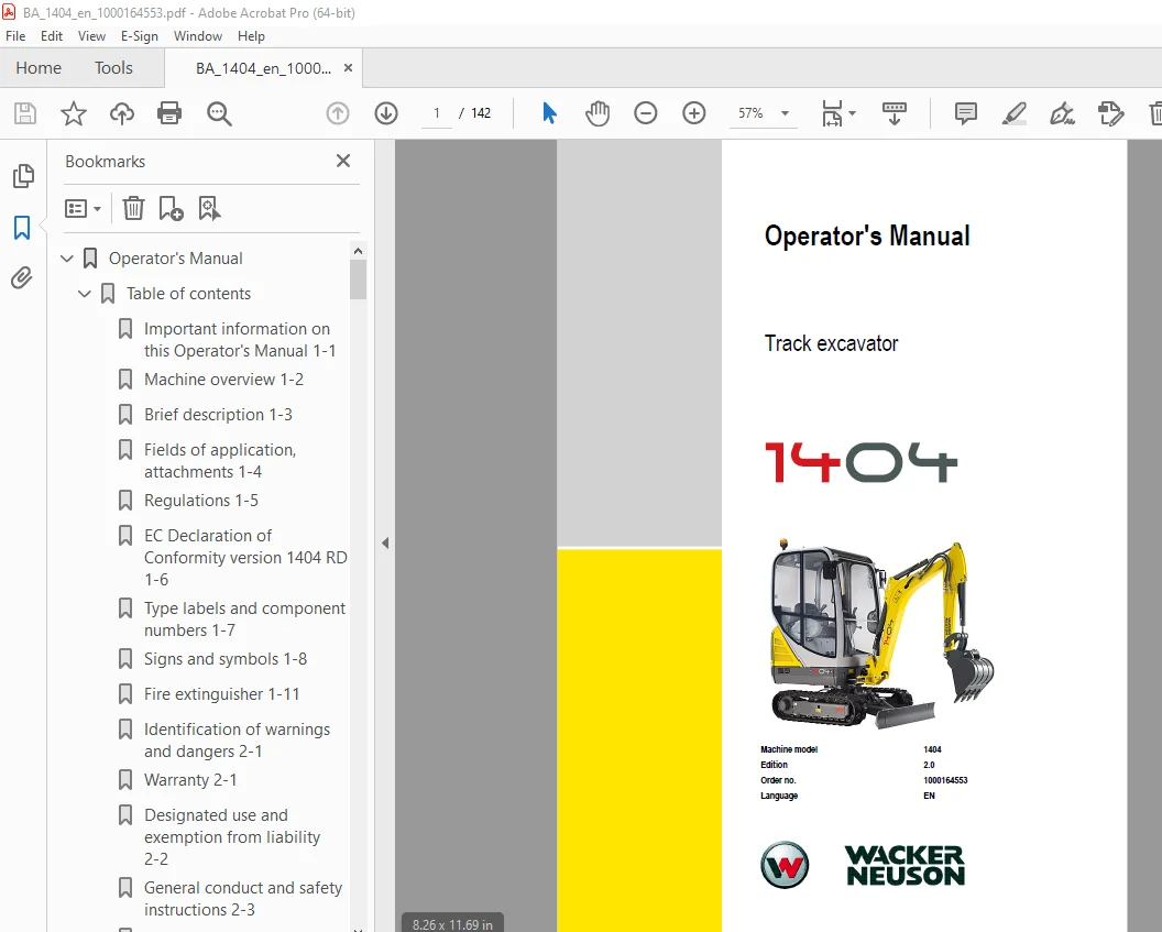
Wacker Neuson 1404 Track Excavator Operator’s Manual 1000164553 – PDF DOWNLOAD
Description
Wacker Neuson 1404 Track Excavator Operator’s Manual 1000164553 – PDF DOWNLOAD
FILE DETAILS:
Wacker Neuson 1404 Track Excavator Operator’s Manual 1000164553 – PDF DOWNLOAD
Language : English
Pages : 142
Downloadable : Yes
File Type : PDF
IMAGES PREVIEW OF THE MANUAL:
DESCRIPTION:
Wacker Neuson 1404 Track Excavator Operator’s Manual 1000164553 – PDF DOWNLOAD
Introduction:
1.1 Important information on this Operator’s Manual:
Please store the Operator’s Manual in the storage bin under the seat.
This Operator’s Manual contains important information on how to work safely, correctly
and economically with the machine. Therefore, it aims not only at new operators, but it also
serves as a reference for experienced ones. It helps to avoid dangerous situations and
reduce repair costs and downtimes. Furthermore, the reliability and the service life of the
machine will be increased by following the instructions in the Operator’s Manual. This is
why the Operator’s Manual must always be kept at hand in the machine.
Your own safety, as well as the safety of others, depends to a great extent on how the
machine is moved and operated. Therefore, carefully read and understand this Operator’s
Manual prior to the first drive. This Operator’s Manual will help to familiarise yourself more
easily with the machine, thereby enabling you to use it more safely and efficiently.
Prior to the first drive, carefully read chapter “Safety Instructions” as well, in order to be
prepared for possible dangerous situations, as it will be too late for it during operation. As a
rule, keep the following in mind:
Careful and prudent working is the best way to avoid accidents!
Operational safety and readiness of the machine do not only depend on your skill, but also
on maintenance and servicing of the machine. This is why regular maintenance and service
work is absolutely necessary. Extensive maintenance and repair work must always be
carried out by an expert with appropriate training. Insist on using original spare parts when
carrying out maintenance and repair work. This ensures operational safety and readiness
of your machine, and maintains its value.
• Special equipment and superstructures are not described in this Operator’s Manual.
• We reserve the right to improve the technical standard of our machines without
adapting the Operator’s Manual.
• Modifying Wacker Neuson products and fitting them with additional equipment and
attachments not included in our delivery program requires Wacker Neuson’s written
authorisation, otherwise warranty and product liability for possible damage caused by
these modifications shall not be applicable.
• Subject to modifications and printing errors.
Your Wacker Neuson dealer will be pleased to answer any further questions regarding the
machine or the Operator’s Manual.
TABLE OF CONTENTS:
Wacker Neuson 1404 Track Excavator Operator’s Manual 1000164553 – PDF DOWNLOAD
Operator’s Manual 1
Table of contents 3
Important information on this Operator’s Manual 1-1 3
Machine overview 1-2 3
Brief description 1-3 3
Fields of application, attachments 1-4 3
Regulations 1-5 3
EC Declaration of Conformity version 1404 RD 1-6 3
Type labels and component numbers 1-7 3
Signs and symbols 1-8 3
Fire extinguisher 1-11 3
Identification of warnings and dangers 2-1 3
Warranty 2-1 3
Designated use and exemption from liability 2-2 3
General conduct and safety instructions 2-3 3
Safety instructions regarding operation 2-5 3
Safety instructions for maintenance 2-8 3
Warning of special hazards 2-10 3
Cab overview 3-2 3
Cab overview (legend) 3-3 3
Instrument panel overview 3-4 3
Instrument panel overview (legend) 3-5 3
Putting into operation 3-6 3
Driving the excavator 3-9 3
Driving on slopes 3-17 4
Working with the machine 3-38 4
Control levers/ISO controls: overview 3-39 4
Changeover valve for SAE/ISO controls (option) 3-42 4
Re-equipping attachments 3-44 5
Grading 3-55 5
Engine trouble 4-1 5
Introduction 5-1 5
Fuel system 5-2 5
Engine lubrication system 5-6 5
Engine cooling system 5-9 5
Air filter 5-13 5
V-belt 5-15 5
Hydraulic system 5-18 5
Pilot valve (from serial number AF01441) 5-22 5
Tracks 5-24 6
Travelling drive 5-26 6
Electrical system 5-27 6
General maintenance work 5-30 6
Fluids and lubricants 5-33 6
Maintenance plan (overview) 5-36 6
Maintenance label 5-40 6
Chassis 6-1 6
Engine 6-1 6
Hydraulic system 6-1 6
Undercarriage and swivel unit 6-2 6
Stabiliser blade 6-2 6
Work hydraulics 6-2 6
Electrical system 6-3 6
Noise levels 6-4 6
Vibration 6-4 6
Coolant compound table 6-4 6
Dimensions model 1404 6-5 6
Lift capacity table 1404 RD 6-6 6
Lift capacity table 1404 RD with long stick (option) 6-7 6
Lift capacity table 1404 RD with cab (option) and telescopic undercarriage (option) 6-8 6
Lift capacity table 1404 RD with cab (option), long stick (option) and telescopic undercarriage (option) 6-9 6
Symbole 7
A 7
B 7
C 7
D 7
F 7
H 7
I 7
L 7
M 7
N 7
O 7
P 7
R 7
S 8
T 8
V 8
W 8
1 Introduction 9
1 1 Important information on this Operator’s Manual 9
1 2 Machine overview 10
1 3 Brief description 11
Travelling drive 11
Work hydraulics 11
Cooling system 11
Cab (ROPS, TOPS and FOPS) 11
1 4 Fields of application, attachments 12
Use: attachment 12
1 5 Regulations 13
1 6 EC Declaration of Conformity version 1404 RD 14
1 7 Type labels and component numbers 15
1 8 Signs and symbols 16
1 9 Fire extinguisher 19
2 Safety instructions 20
2 1 Identification of warnings and dangers 20
2 2 Warranty 20
2 3 Designated use and exemption from liability 21
2 4 General conduct and safety instructions 22
Organisational measures 22
Selection and qualification of staff, basic responsibilities 23
2 5 Safety instructions regarding operation 24
Normal operation 24
Applications with lifting gear 26
Trailers and attachments 26
Transport 26
2 6 Safety instructions for maintenance 27
2 7 Warning of special hazards 29
Electrical energy 29
Gas, dust, steam, smoke 29
Hydraulics 29
Noise 29
Oil, grease and other chemical substances 30
Battery 30
Air intake 30
Tracks 30
3 Operation 31
3 1 Cab overview 32
3 2 Cab overview (legend) 33
3 3 Instrument panel overview 34
3 4 Instrument panel overview (legend) 35
3 5 Putting into operation 36
Safety instructions 36
Putting the machine into operation for the first time 36
Running-in period 36
Check lists 37
Start-up checklist 37
Operation checklist 38
Parking checklist 38
3 6 Driving the excavator 39
Preheating start switch: overview 39
Throttle lever: overview 39
Telltales and warning lights: overview 40
Before starting the engine 42
Starting the engine: general 42
Procedure 42
Starting with the drive interlock (option) 43
Starting at low temperatures 44
When the engine has started 44
Engine warm-up 44
Jump-starting the engine (supply battery) 45
Special instructions for driving on public roads 45
Moving off 46
Drive levers 46
Hydraulic brake 46
3 7 Driving on slopes 47
Specific safety instructions 47
Driving on slopes 48
Stabiliser blade control/telescopic undercarriage (option) 49
Parking the machine 51
Parking the machine on slopes 51
Light system 52
Roof lights (option) 52
Interior light 52
Rotating beacon (option) 53
Cab heating and ventilation 53
Heating adjustment 54
Washer system 54
Tank for washer system 54
Seat adjustment 55
Weight adjustment 55
Horizontal adjustment 55
Backrest adjustment 56
Seat belt 56
Emergency exit (with cab option) 57
Front window (with cab option) 58
Door (with cab option) 59
Engine cover 60
Battery master switch (model 1404) 60
Exit through the door (with standard cab option) 61
Towing the track excavator 62
Towing 62
Crane handling the machine 63
Loading and transporting the machine 66
Tying down the machine 67
3 8 Working with the machine 68
General safety instructions 68
3 9 Control levers/ISO controls: overview 69
Left-hand side control lever 69
Boom swivel controls 69
Auxiliary hydraulics 70
Right-hand side control lever 70
Lowering the boom at engine standstill/energy failure 71
Rotating the upper carriage 71
Swivel unit brake 71
3 10 Changeover valve for SAE/ISO controls (option) 72
Left-hand side control lever 72
Right-hand side control lever 72
Directional valve position 73
Directional valve 73
3 11 Re-equipping attachments 74
Specific safety instructions 74
Removing a bucket 74
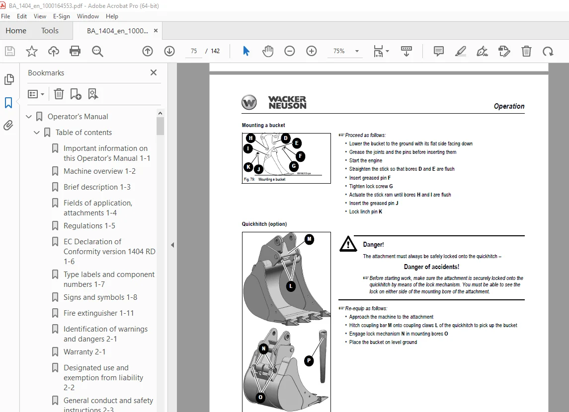
Mounting a bucket 75
Quickhitch (option) 75
Hydraulic quickhitch (option) 77
Maintenance 77
Operation 78
Connections for auxiliary hydraulics 79
Grab couplings 80
Attachments 81
Working with the standard bucket 81
Inadmissible work procedures 81
Excavator work position 82
Bucket position when digging 82
Excavating trenches 83
Loading 83
Grading 83
Excavating trenches sideways 84
3 12 Grading 85
Grading 85
Working alongside trenches 85
4 Troubleshooting 87
4 1 Engine trouble 87
5 Maintenance 89
5 1 Introduction 89
5 2 Fuel system 90
Specific safety instructions 90
Refuelling 90
Draining the fuel 91
Stationary fuel pumps 91
Diesel fuel specification 92
Bleeding the fuel system 92
Fuel prefilter with water separator 93
5 3 Engine lubrication system 94
Checking the oil level 94
Draining engine oil 95
Filling up engine oil 96
5 4 Engine cooling system 97
Specific safety instructions 97
Checking/filling up coolant 98
5 5 Air filter 101
Air intake 101
Replacing the filter 102
5 6 V-belt 103
Checking V-belt tension 103
Tightening the V-belt (dynamo) 104
Tightening the V-belt (alternator) 105
5 7 Hydraulic system 106
Specific safety instructions 106
Checking the hydraulic oil level 106
Filling up hydraulic oil 108
Important information for the use of biodegradable oil 109
5 8 Pilot valve (from serial number AF01441) 110
Checking hydraulic pressure lines 111
5 9 Tracks 112
Checking track tension 112
Setting the tracks 113
5 10 Travelling drive 114
Checking the oil level and filling up oil 114
Draining oil 114
Maintenance of attachments 114
5 11 Electrical system 115
Specific safety instructions 115
Service and maintenance work at regular intervals 115
Instructions concerning specific components 116
Alternator 116
Battery 117
5 12 General maintenance work 118
Cleaning 118
General instructions for all areas of the machine 118
Inside the cab 119
Exterior of the machine 119
Engine compartment 119
Screw connections and attachments 120
Pivots and hinges 120
5 13 Fluids and lubricants 121
Additional oil change and filter replacement (hydraulics) 122
5 14 Maintenance plan (overview) 124
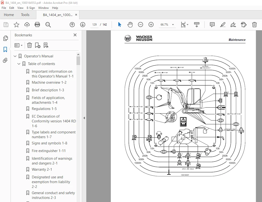
5 15 Maintenance label 128
Explanation of symbols on the maintenance label 128
6 Specifications 131
6 1 Chassis 131
6 2 Engine 131
6 3 Hydraulic system 131
6 4 Undercarriage and swivel unit 132
6 5 Stabiliser blade 132
6 6 Work hydraulics 132
6 7 Electrical system 133
Fuses on left-hand side control lever base 133
Main fuse and relays in the engine compartment 133
6 8 Noise levels 134
6 9 Vibration 134
6 10 Coolant compound table 134
6 11 Dimensions model 1404 135
6 12 Lift capacity table 1404 RD 136
6 13 Lift capacity table 1404 RD with long stick (option) 137
6 14 Lift capacity table 1404 RD with cab (option) and telescopic undercarriage (option) 138
6 15 Lift capacity table 1404 RD with cab (option), long stick (option) and telescopic undercarriage (option) 139
S.V 02/01/2025