Wacker Neuson 38Z3 Track Excavator Service Manual 1000160891 PDF
$28.95
Wacker Neuson 38Z3 Track Excavator Service Manual 1000160891 – PDF DOWNLOAD
Description
Wacker Neuson 38Z3 Track Excavator Service Manual 1000160891 – PDF DOWNLOAD
FILE DETAILS:
Wacker Neuson 38Z3 Track Excavator Service Manual 1000160891 – PDF DOWNLOAD
Language : English
Pages : 226
Downloadable : Yes
File Type : PDF
IMAGES PREVIEW OF THE MANUAL:
TABLE OF CONTENTS:
Wacker Neuson 38Z3 Track Excavator Service Manual 1000160891 – PDF DOWNLOAD
Operation
Important information on this service manual 1-1
Identification of warnings and dangers 1-2
Designated use and exemption from liability 1-3
Type labels and component numbers 1-4
Machine: overview 1-6
Cab overview 1-7
Cab (legend) 1-8
Instrument panel overview (up to serial no AE02803) 1-9
Instrument panel (legend) 1-10
Instrument panel overview (from serial no AG00573) 1-11
Instrument panel (legend) 1-12
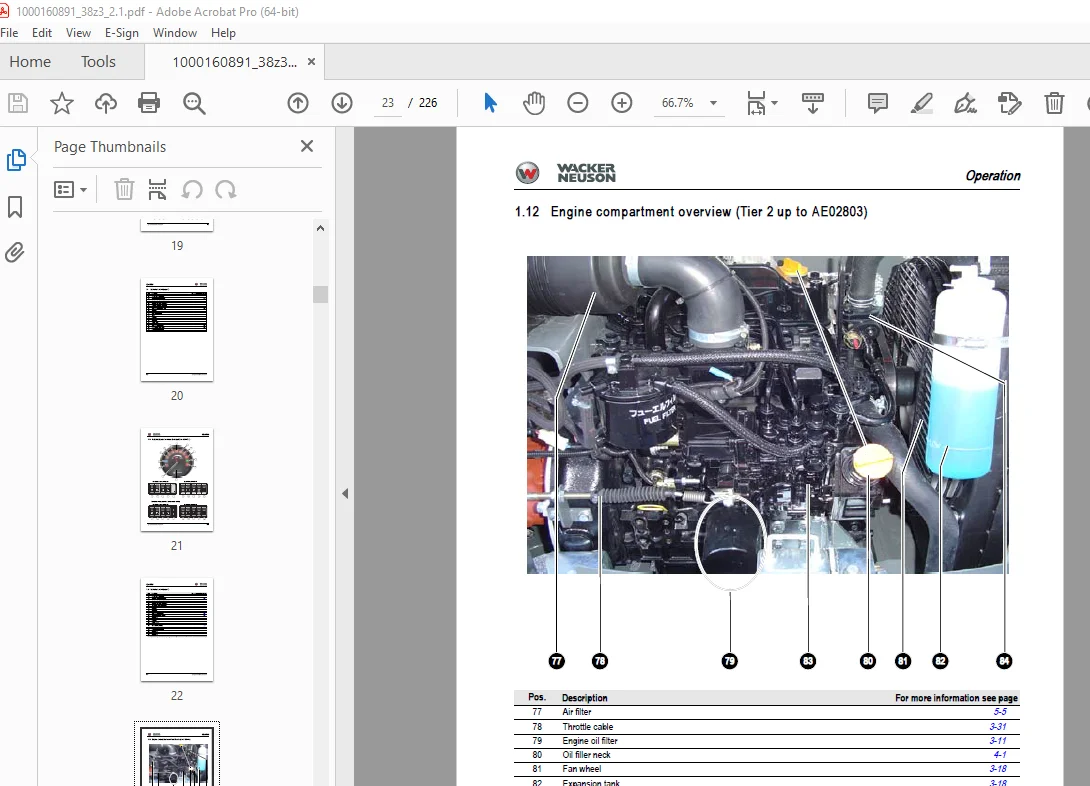
Engine compartment overview (Tier 2 up to AE02803) 1-13
Engine compartment overview (Tier 3A from AG00573) 1-14
Chassis overview 1-15
Tilting the cab 1-16
Specifications
Chassis 2-1
Engine 2-1
Fuel injection pump 2-2
Engine capacities 2-2
Engine tightening torques 2-2
Hydraulic system 2-3
Auxiliary hydraulics oil flow 2-3
Undercarriage and swivel unit 2-4
Stabiliser blade 2-4
Screwable hose burst valve 2-4
Electric system 2-5
Fuse box in instrument panel 2-5
Main fuse box with relays underneath the cab 2-5
Relays 2-6
Noise levels 2-6
Vibration 2-6
Coolant compound table 2-7
Model-specific tightening torques 2-7
General tightening torques 2-7
Tightening torques for hydraulic screw connections (dry assembly) 2-7
Tightening torques for high-resistance screw connections 2-9
Dimensions model 38Z3 2-11
Lift capacity table 38Z3 2-12
Lift capacity table 38Z3 short stick + extra weight 2-13
Lift capacity table 38Z3 long stick 2-14
Lift capacity table 38Z3 with long stick + extra weight 2-15
Kinematics 2-16
Attachments 2-17
Maintenance
Fluids and lubricants 3-1
Additional oil change and filter replacement (hydraulics) 3-2
Maintenance label 3-3
Explanation of symbols on the maintenance label 3-3
Maintenance plan (overview) 3-5
Service package 3-8
Up to serial no AE02803 3-8
From serial no AG00573 3-8
Table of contents
I-2 SERV-HB 38Z3 EN – Edition 2 1 * 38z3s2_1IVZ fm
Table of contents
Introduction 3-8
Fuel system 3-9
Specific safety instructions 3-9
Refuelling 3-9
Stationary fuel pumps 3-10
Diesel fuel specification 3-10
Bleeding the fuel system 3-10
Emptying the fuel tank 3-11
Fuel prefilter with water separator 3-11
Replacing the fuel filter 3-12
Engine lubrication system 3-13
Checking the oil level 3-13
Filling up engine oil 3-14
Changing engine oil 3-15
Replacing the engine oil filter cartridge 3-16
Cooling system 3-17
Specific safety instructions 3-17
Checking/filling up coolant 3-18
Filling up coolant 3-19
Draining coolant 3-19
Air filter 3-20
Replacing the filter 3-21
Functional check once a week of the dust valve 3-22
V-belt 3-23
Checking V-belt tension 3-23
Retightening the V-belt 3-24
Checking the V-belt of the air conditioning system 3-25
Tightening the V-belt of the air conditioning system 3-26
Pressure check 3-27
General 3-27
Checking pilot control pressure 3-27
Pressure check of variable displacement pump P1 3-28
Pressure check of variable displacement pump P2 3-29
Pressure check of gear pump P3 3-30
Secondary pressure limiting valve of the gear motor 3-30
Measuring ports: overview 3-31
Primary pressure limiting valves 3-31
Test report 3-32
Hydraulic system 3-34
Specific safety instructions 3-34
Checking the hydraulic oil level 3-35
Filling up hydraulic oil 3-36
Changing hydraulic oil 3-36
Monitoring the hydraulic oil reflux filter 3-37
Checking hydraulic pressure lines 3-38
Travelling drive 3-39
Checking the oil level and filling up oil 3-39
Draining oil 3-39
Chains 3-40
Checking chain tension 3-40
Setting the chains 3-41
Lubrication work 3-42
Stabiliser blade 3-42
Lubrication points on the swivelling console 3-42
Boom lubrication points 3-43
Lubrication points on the stick 3-43
Lubrication strip 3-44
SERV-HB 38Z3 EN – Edition 2 1 * 38z3s2_1IVZ fm I-3
Table of contents
Maintenance of attachments 3-44
Electric system 3-45
Specific safety instructions 3-45
Service and maintenance work at regular intervals 3-45
Instructions concerning specific components 3-46
Alternator 3-46
Battery 3-47
Cab 3-48
Replacing the cab filter 3-48
General maintenance work 3-49
Cleaning 3-49
General instructions for all areas of the machine 3-49
Inside the cab 3-50
Exterior of the machine 3-50
Engine compartment 3-50
Screw connections and attachments 3-50
Pivots and hinges 3-50
Engine
Engine overview 3TNV88-PNS (Tier 2) 4-1
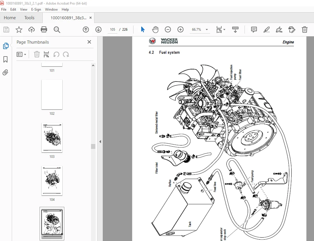
Fuel system 4-3
Checking and adjusting valve tip clearance 4-4
Tightening order for cylinder head bolts 4-5
Checking the injection nozzles 4-6
Pressure check 4-6
Checking the nozzle jet 4-6
Injection time 4-7
Checking injection time 4-7
Setting injection time 4-8
Replacement of fuel injection pump 4-8
Adjusting engine revs 4-9
Compression 4-9
Checking the coolant thermostat 4-10
Checking the thermal switch 4-11
Oil pressure switch 4-11
Checking the coolant circuit 4-11
Engine overview 3TNV88-BPNS (Tier 3A) 4-12
Fuel system 4-14
Removing the cylinder-head cover 4-15
Checking and adjusting valve tip clearance 4-15
Tightening order for cylinder head bolts 4-16
Checking the injection nozzles 4-17
Pressure check 4-17
Checking the nozzle jet 4-17
Injection time 4-18
Checking injection time 4-18
Setting injection time 4-19
Replacement of fuel injection pump 4-20
Adjusting engine revs 4-21
Compression 4-21
Checking the coolant thermostat 4-21
Checking the thermal switch 4-22
Oil pressure switch 4-22
Checking the coolant circuit 4-23
Engine trouble 4-23
Hydraulic system
Hydraulic pump PVD-1B-32BP-11G5-4904A (up to AE02803)
I-4 SERV-HB 38Z3 EN – Edition 2 1 * 38z3s2_1IVZ fm
Table of contents
PVD-1B-34BP-10G5 (from AG00573) 5-1
Pump unit: exploded view 5-3
Pilot oil supply unit 5-4
Main valve block 5-5
Ports 5-5
Legend 5-6
Main valve block diagram 5-7
Pressure limiting valves 5-8
Pump assignment 5-9
Drive counterbalancing system 5-10
Pump assignment for drive counterbalancing 5-10
Regeneration – stick section 5-11
Bucket pre-tension 5-11
Flow rate adjustment of auxiliary hydraulics 5-12
Pilot valves 5-13
Joystick 5-13
Pilot valve (driving) 5-15
Pilot valve for auxiliary hydraulics 5-17
Valves 5-18
7/2 directional valve (changeover valve) 5-18
Changeover valve for SAE/ISO controls (option) 5-19
Travelling drive up to no AE00854 5-20
Function 5-21
Travelling drive starting no AE00855 5-23
Function 5-24
Swivel unit 5-26
Parking brake/multidisc brake function 5-27
Swivel joint 5-30
Sealing 5-30
Breather filter 5-31
Troubleshooting in the hydraulic system 5-32
Hydraulics diagram A4 5-33
Hydraulics diagram (legend) 5-34
Hydraulics diagram 38Z3 A3 5-35
Option diagram 1 5-36
Option diagram 2 5-37
Main valve block diagram 38Z3 A3 5-38
Electric system
Ohm’s Law (current, voltage, resistance); power 6-1
Measuring equipment, measuring methods 6-1
Cable colour coding 6-3
Relays 6-3
Use, mode of function 6-3
Electric units 6-4
Fuse box in instrument panel 6-4
Main fuse box with relays 6-4
Relays 6-5
Socket 6-5
Joystick tip switches 6-6
Joystick (left) 6-6
Joystick (right) 6-6
Instrument panel overview 6-6
Switch overview (up to serial no AE02803) 6-7
Switch overview (from serial no AG00573) 6-8
Alternator 6-9
Starter 6-9
SERV-HB 38Z3 EN – Edition 2 1 * 38z3s2_1IVZ fm I-5
Table of contents
Wiring diagram A4 38Z3 (legend) 6-11
Wiring diagram A4 6-12
Engine wiring harness (legend) 6-13
Engine wiring harness A4 6-14
Cab wiring harness A4 (legend) 6-15
Cab wiring harness A4 6-16
Roof wiring harness A4 6-17
Revs control wiring harness (option) 6-18
Wiring diagram A3 (legend) 6-20
Wiring diagram A3 6-21
Engine wiring harness A3 (legend) 6-22
Engine wiring harness A3 6-23
Cab wiring harness A3 (legend) 6-24
Cab wiring harness A3 6-25
Roof wiring harness A3 6-26
Revs control wiring harness (option) 6-27
Options
Air conditioning 7-3
Specific safety instructions 7-3
Specifications 7-3
Components 7-5
Compressor 7-6
Filling up the air conditioning system 7-7
Maintenance 7-8
Troubleshooting 7-9
Counterweight 7-10
Specifications 7-10
Long stick 7-10
Specifications 7-10
Control circuit (pipework) connections for grab 7-11
Attachments 7-11
3rd control circuit connections 7-12
Auxiliary hydraulics connections 7-12
Safe load indicator DE (safety valve for boom) 7-13
Position 7-13
Setting the pressure switch 7-13
Function 7-14
Wiring diagram 7-14
Safe load indicator FR (safety valves for boom and stick) 7-15
Position 7-15
Setting the pressure switch 7-15
Function 7-16
Wiring diagram 7-17
3rd control circuit 7-18
Function 7-18
Diagram 7-18
Drive interlock (antitheft protection) 7-19
Position 7-19
Disabling the drive interlock 7-19
Enabling the drive interlock 7-19
Programming 7-19
Proportional controls 7-21
Function 7-21
Ports 7-21
Overview 7-22
Wiring harness 7-23
I-6 SERV-HB 38Z3 EN – Edition 2 1 * 38z3s2_1IVZ fm
Table of contents
Control valve plug assignment 7-24
Safety features 7-25
Measures to be taken in case of malfunctions 7-25
Diagnosis display 7-25
Fuel-filling pump 7-27
Connections 7-28
Service valve 7-29
Function 7-29
Automatic revs setting (Tier 3A from AG00573) 7-30
Installation 7-31
DESCRIPTION:
Wacker Neuson 38Z3 Track Excavator Service Manual 1000160891 – PDF DOWNLOAD
Important information on this service manual:
- This service manual contains important information on how to service your machine safely,
correctly and economically. Therefore, it aims not only at new operators, but it also serves
as a reference for experienced ones. It helps to avoid dangerous situations and reduce
repair costs and downtimes. Furthermore, the reliability and the service life of the machine
will be increased by following the instructions in the service manual. - Careful and prudent working is the best way to avoid accidents!
- Operational safety and readiness of the machine do not only depend on your skill, but also
on maintenance and servicing of the machine. - Insist on using original spare parts when carrying out maintenance and repair work. This
ensures operational safety and readiness of your machine, and maintains its value.
Will be pleased to answer any further questions regarding the machine or the service
manual.
S.V 31/12/24