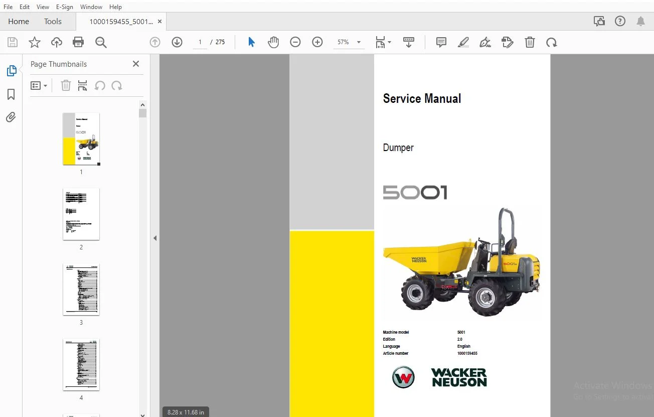
WACKER NEUSON 5001 DUMPER SERVICE MANUAL 1000159455 – PDF DOWNLOAD
$27.95
WACKER NEUSON 5001 DUMPER SERVICE MANUAL 1000159455 – PDF DOWNLOAD
Description
WACKER NEUSON 5001 DUMPER SERVICE MANUAL 1000159455 – PDF DOWNLOAD
FILE DETAILS:
WACKER NEUSON 5001 DUMPER SERVICE MANUAL 1000159455 – PDF DOWNLOAD
Language : English
Pages : 275
Downloadable : Yes
File Type : PDF
IMAGES PREVIEW OF THE MANUAL:
TABLE OF CONTENTS:
WACKER NEUSON 5001 DUMPER SERVICE MANUAL 1000159455 – PDF DOWNLOAD
1 Operation.............................................................................................. 10
	1.1 Important information on this service manual..................................................... 10
	1.2 Identification of warnings and dangers........................................................... 11
	1.3 Designated use and exemption from liability...................................................... 12
	1.4 Type labels and component numbers................................................................ 13
	1.5 Machine overview................................................................................. 15
	1.6 Control elements from AB45091D to AC45157D (overview)............................................ 16
		Operating equipment (legend)..................................................................... 16
	1.7 Control elements from AD51001D (overview)........................................................ 17
	1.8 Maintenance strut................................................................................ 18
		Centre pivot strut............................................................................... 19
2 Specifications......................................................................................... 22
	2.1 Chassis.......................................................................................... 22
	2.2 Engine........................................................................................... 22
		Engine capacities................................................................................ 23
		Engine tightening torques........................................................................ 23
	2.3 Travelling drive................................................................................. 24
	2.4 Brakes........................................................................................... 24
	2.5 Steering system.................................................................................. 24
	2.6 Work hydraulics.................................................................................. 25
	2.7 Loader unit...................................................................................... 25
	2.8 Drive specifications............................................................................. 25
	2.9 Vibration........................................................................................ 25
	2.10 Electrical system............................................................................... 26
		Fuse box on the instrument panel from AB45091 to AC45157D........................................ 26
		Fuse box in relay box from AD51001D.............................................................. 26
		Relays (from AB45091D to AB45291D)............................................................... 27
		Relays (from AC45039D to AC45157D)............................................................... 27
		Relays (from AD51001D)........................................................................... 27
	2.11 Tyres........................................................................................... 28
	2.12 Axle mounting................................................................................... 28
	2.13 Noise levels.................................................................................... 28
	2.14 Coolant compound table.......................................................................... 28
	2.15 General tightening torques...................................................................... 29
		Tightening torques for hydraulic screw connections (dry assembly)................................ 29
		Tightening torques for high-resistance screw connections......................................... 31
		Tightening torques for Nordlock lock washers..................................................... 32
	2.16 Dimensions model 5001 AB45091D to AC45157D...................................................... 33
	2.17 Dimensions model 5001 from AD51001D............................................................. 34
3 Maintenance............................................................................................ 36
	3.1 Fluids and lubricants............................................................................ 36
	3.2 Maintenance plan (overview)...................................................................... 38
		Introduction..................................................................................... 41
	3.2 Fuel system...................................................................................... 42
		Specific safety instructions..................................................................... 42
		Refuelling....................................................................................... 42
		Stationary fuel pumps............................................................................ 43
		Diesel fuel specification........................................................................ 43
		Bleeding the fuel system......................................................................... 43
		Bleeding automatically (Yanmar engine)........................................................... 44
		Bleeding with a manual pump (Deutz engine)....................................................... 44
		Cleaning the filter screen insert................................................................ 44
		Yanmar fuel prefilter with water separator....................................................... 45
		Deutz fuel filter with water separator........................................................... 45
		Replacing the fuel filter........................................................................ 46
		Replacing the Deutz fuel filter.................................................................. 46
	3.3 Engine lubrication system........................................................................ 47
		Checking the oil level........................................................................... 47
		Filling up engine oil............................................................................ 48
		Changing engine oil.............................................................................. 49
		Replacing the engine oil filter cartridge........................................................ 50
	3.4 Cooling system................................................................................... 51
		Specific safety instructions..................................................................... 51
		Checking/filling up coolant...................................................................... 52
		Draining coolant................................................................................. 54
	3.5 Air filter....................................................................................... 55
		Weekly check of air filter for dirt.............................................................. 55
		Replacing the filter............................................................................. 56
		Functional check once a week of the dust valve................................................... 57
	3.6 V-belts.......................................................................................... 57
		Checking V-belt tension.......................................................................... 57
		Retightening V-belts............................................................................. 58
	3.7 Hydraulic system................................................................................. 60
		Specific safety instructions..................................................................... 60
		Checking the hydraulic oil level................................................................. 61
		Filling up hydraulic oil......................................................................... 61
		Changing hydraulic oil........................................................................... 62
		Monitoring the hydraulic oil reflux filter....................................................... 62
		Replacing the hydraulic oil reflux filter........................................................ 62
		Checking hydraulic pressure lines................................................................ 63
	3.8 Lubrication points............................................................................... 64
	3.9 Tyre maintenance................................................................................. 65
		Checks once a day................................................................................ 65
		Checks once a week............................................................................... 65
	3.10 Changing wheels................................................................................. 66
		Removing......................................................................................... 66
		Fitting the wheels............................................................................... 66
	3.11 Electrical system............................................................................... 67
		Specific safety instructions..................................................................... 67
		Service and maintenance work at regular intervals................................................ 67
		Instructions concerning specific components...................................................... 68
		Alternator....................................................................................... 68
		Battery.......................................................................................... 69
	3.12 Battery master switch........................................................................... 70
	3.13 General maintenance work........................................................................ 71
		Cleaning......................................................................................... 71
		General instructions for all areas of the machine................................................ 71
		Screw connections and attachments................................................................ 71
		Pivots and hinges................................................................................ 71
	3.14 Test report from AD51001D....................................................................... 72
4 Engine................................................................................................. 74
	4.1 Engine overview 4TNV84T-KNSV (up to AB45291D).................................................... 74
	4.2 Fuel system...................................................................................... 76
		Checking and adjusting valve lash................................................................ 77
		Tightening order for cylinder head bolts......................................................... 78
	4.3 Checking the injection nozzles................................................................... 79
		Pressure check................................................................................... 79
		Checking the nozzle jet.......................................................................... 79
		Injection time................................................................................... 80
	4.4 Adjusting engine speed........................................................................... 81
	4.5 Compression...................................................................................... 81
	4.6 Checking the coolant thermostat.................................................................. 82
		Checking the thermal switch...................................................................... 82
	4.7 Oil pressure switch.............................................................................. 83
	4.8 Checking the coolant circuit..................................................................... 83
	4.9 Clutch........................................................................................... 84
	4.10 Engine trouble.................................................................................. 84
	4.11 Engine overview DEUTZ F4M 2011 (from AC45039D to AC45157D)...................................... 86
	4.12 Fuel system..................................................................................... 89
	4.13 Checking and adjusting valve lash............................................................... 90
	4.14 Checking and adjusting the fuel injectors....................................................... 91
	4.15 Adjusting engine speed.......................................................................... 93
	4.16 Compression pressure............................................................................ 94
	4.17 Removing/mounting the cylinder head............................................................. 95
		Intake/exhaust manifold.......................................................................... 98
	4.18 Replacing the injection pump/setting fuel injection time........................................ 98
	4.19 Oil pressure switch.............................................................................102
	4.20 Engine trouble..................................................................................103
	4.21 Engine overview DEUTZ D2011 L04w (from AD51001D)................................................105
	4.22 Fuel system.....................................................................................108
	4.23 Checking and adjusting valve lash...............................................................109
	4.24 Checking and adjusting the fuel injectors.......................................................111
	4.25 Adjusting engine speed..........................................................................113
	4.26 Water pump and thermostat.......................................................................113
	4.27 Exhaust gas recirculation (external)............................................................114
	4.28 Compression pressure............................................................................115
	4.29 Removing/mounting the cylinder head.............................................................116
		Intake/exhaust manifold..........................................................................119
	4.30 Replacing the injection pump/setting fuel injection time........................................120
	4.31 Oil pressure switch.............................................................................124
	4.32 Engine trouble..................................................................................125
5 Travelling drive.......................................................................................130
	5.1 Travelling drive overview........................................................................130
	5.2 Variable displacement pump A4VG56DA..............................................................131
		Variable displacement pump: diagram..............................................................134
		Variable displacement pump: diagram..............................................................135
		Power train overview.............................................................................136
		Connecting plate with valves.....................................................................137
	5.3 Replacing components.............................................................................138
		Replacing the rotary shaft lip seal..............................................................138
		Replacing seals..................................................................................139
		Replacing valve seals............................................................................140
	5.4 Variable displacement motor......................................................................144
		Variable displacement motor diagram..............................................................146
	5.5 Replacing components.............................................................................146
		Replacing the rotary shaft lip seal..............................................................146
		Replacing the sealing nut........................................................................147
		Replacing the control unit.......................................................................148
		Sealing the flush valve/cover....................................................................148
	5.6 Towing and transporting the machine..............................................................149
		Safety instructions..............................................................................149
		Towing...........................................................................................149
		Opening the high-pressure circuit................................................................149
	5.7 Test instructions for variable displacement pump.................................................150
		High pressure check..............................................................................150
		Check: boost pressure............................................................................151
		Check: setting pressure..........................................................................152
		Control initiation and end.......................................................................152
		Check: mechanical zero position..................................................................152
	5.8 Test instructions for variable displacement motor................................................153
		Checking control initiation......................................................................153
		Control initiation and end.......................................................................154
6 Axles..................................................................................................156
	6.1 Axle type label..................................................................................156
	6.2 Drain, fill and check plug.......................................................................157
	6.3 Tightening torque................................................................................158
		Wheel screws.....................................................................................158
		General tightening torques (Nm)..................................................................158
	6.4 Transfer gearbox.................................................................................160
	6.5 Semiaxles........................................................................................162
	6.6 Wheel hub........................................................................................166
	6.7 Front axle brake.................................................................................168
	6.8 Cardan shaft.....................................................................................176
	6.9 Dismantling and assembling the axle..............................................................177
		Dismantling the planetary drive and the semiaxle.................................................177
		Assembling the planetary drive and the semiaxle..................................................178
		Dismantling the differential.....................................................................181
		Assembling the differential......................................................................183
		Dismantling the transfer gearbox.................................................................185
		Assembling the transfer gearbox..................................................................186
		Removing the bevel gear..........................................................................187
		Installing the bevel gear........................................................................189
		Special tools for axles..........................................................................194
7 Brakes.................................................................................................200
	7.1 Brake circuit....................................................................................200
	7.2 Parking brake....................................................................................201
	7.3 Dismantling and assembling the brakes and the parking brake......................................202
		Dismantling the brakes...........................................................................202
		Assembling the brakes............................................................................204
8 Steering system........................................................................................210
	8.1 Steering circuit up to AC45157D..................................................................210
	8.2 Steering unit: diagram...........................................................................211
		Function.........................................................................................212
	8.3 Steering unit connections........................................................................212
	8.4 Steering unit overview...........................................................................213
		Priority valve overview (up to AC45157D).........................................................213
		Priority valve (legend)..........................................................................213
		Steering unit....................................................................................214
		Steering unit (legend)...........................................................................215
9 Hydraulic system.......................................................................................218
	9.1 Manual spool overview and connections (Yanmar engine up to AB45291D).............................218
	9.2 Manual spool overview and connections (Deutz engine up to AC45157D)..............................219
	9.3 Manual spool overview and connections (from AD51001D)............................................220
	9.4 Valves...........................................................................................221
		Double shock valve (from AD51001D)...............................................................221
		Check valve (up to AC45157D).....................................................................221
	9.5 Dumping the skip: hydraulics diagram (up to AC45157D)............................................222
	9.6 Swivelling the skip: hydraulics diagram (up to AC45157D).........................................223
	9.7 Dumping and swivelling the skip: hydraulics diagram (from AD51001D)..............................224
	9.8 Test instructions................................................................................225
		Checking the work hydraulics (up to AC45157D)....................................................225
		Checking the work hydraulics (from AD51001D).....................................................226
	9.9 Diagram A4 (up to AC45157D)......................................................................227
	9.10 Diagram (legend)................................................................................227
	9.11 Diagram A4 (from AD51001D)......................................................................228
	9.12 Diagram (legend)................................................................................229
	9.13 Hydraulics diagram A3 (up to AC45157D)..........................................................231
	9.14 Hydraulics diagram A3 (starting AD51001D).......................................................232
10 Electrical system.....................................................................................234
	10.1 Ohm's Law (current, voltage, resistance); power.................................................234
	10.2 Measuring equipment, measuring methods..........................................................234
	10.3 Relays..........................................................................................235
		Use, mode of function............................................................................235
	10.4 Electric units..................................................................................236
	10.5 Fuse box........................................................................................236
		Fuse box on the instrument panel (from AB45091 to AC45157D)......................................236
		Fuse box in relay box (from AD51001D)............................................................237
		Relays (from AB45091D to AB45291D)...............................................................237
		Relays (from AC45039D to AC45157D)...............................................................237
		Relays (from AD51001D)...........................................................................238
	10.6 Control elements from AB45091D to AC45157D (overview)...........................................239
		Operating equipment (legend).....................................................................239
	10.7 Control elements from AD51001D (overview).......................................................240
	10.8.................................................................................................240
	10.9 Wiring diagram legend (up to AB45291D)..........................................................242
	10.10 Wiring diagram version 1 A4 (up to AB45291D)...................................................243
	10.11 Wiring diagram version 2 A4 (from AC45039D to AC45157D)........................................244
	10.12 Wiring diagram version 3 A4 (from AD51001D)....................................................245
	10.13 Wiring harness legend 1000115009 main wiring harness (up to AB45291D)..........................246
	10.14 Wiring harness 1000115009: main wiring harness (up to AB45291D)................................248
	10.15 Main wiring harness legend (from AC45039D to AC45157D).........................................249
	10.16 Main wiring harness (from AC45039D to AC45157D)................................................250
	10.17 Main wiring harness (from AD51001D)............................................................251
	10.18 Engine wiring harness legend (from AC45039D to AC45157D).......................................252
	10.19 Engine wiring harness (from AC45039D to AC45157D)..............................................253
	10.20 STVO (Austrian road traffic regulations) wiring harness and rotating beacon (from AD51001D)....254
	10.21 Connector assignment for light switch and forwards-reverse control.............................255
	10.22 Wiring diagram legend A3 up to serial no. AB45291D.............................................258
	10.23 Wiring diagram A3 up to AB45291D...............................................................259
	10.24 Wiring diagram A3 (from AC45039D to AC45157D)..................................................260
	10.25 Wiring diagram A3 (from AD51001D)..............................................................261
	10.26 Wiring harness legend 1000115009 main wiring harness (up to AB45291D)..........................262
	10.27 Wiring harness 1000115009: main wiring harness (up to AB45291D)................................263
	10.28 Wiring harness 1000181595 main wiring harness (from AD51001D)..................................264
	10.29 Main wiring harness legend 1000181595A (from AD51001D).........................................265
	10.30 Wiring harness 1000181595A main wiring harness (from AD51001D).................................266
	10.31 Wiring harness legend 1000115414 engine wiring harness (up to AB45291D)........................267
	10.32 Wiring harness 1000115414 engine wiring harness (up to AB45291D)...............................268
	10.33 Wiring harness legend: telltale/indicator base – ignition lock base (up to AB45291D)...........269
	10.34 Wiring harness 1000075039 telltale/indicator base (up to AB45291D).............................270
	10.35 Connector assignment for light switch and forwards-reverse control.............................271
	10.36 Main wiring harness legend (from AC45039D to AC45157D).........................................272
	10.37 Main wiring harness (from AC45039D to AC45157D)................................................273
DESCRIPTION:
WACKER NEUSON 5001 DUMPER SERVICE MANUAL 1000159455 – PDF DOWNLOAD
This service manual contains important information on how to service your machine safely, correctly and economically. Therefore, it aims not only at new operators, but it also serves as a reference for experienced ones. It helps to avoid dangerous situations and reduce repair costs and downtimes. Furthermore, the reliability and the service life of the machine will be increased by following the instructions in the service manual.
Careful and prudent working is the best way to avoid accidents!
Operational safety and readiness of the machine do not only depend on your skill, but also on maintenance and servicing of the machine.
Insist on using original spare parts when carrying out maintenance and repair work. This ensures operational safety and readiness of your machine, and maintains its value.
will be pleased to answer any further questions regarding the machine or the service manual.
Your Wacker Neuson dealer
S.S 03/01/2025