Wacker Neuson 50Z3 Track Excavator Service Manual 1000129833 PDF
$28.95
Wacker Neuson 50Z3 Track Excavator Service Manual 1000129833 – PDF DOWNLOAD
Description
Wacker Neuson 50Z3 Track Excavator Service Manual 1000129833 – PDF DOWNLOAD
FILE DETAILS:
Wacker Neuson 50Z3 Track Excavator Service Manual 1000129833 – PDF DOWNLOAD
Language : English
Pages : 262
Downloadable : Yes
File Type : PDF
IMAGES PREVIEW OF THE MANUAL:
TABLE OF CONTENTS:
Wacker Neuson 50Z3 Track Excavator Service Manual 1000129833 – PDF DOWNLOAD
1 Operation 11
1 1 Important information on this service manual 11
1 2 Identification of warnings and dangers 12
1 3 Designated use and exemption from liability 13
1 4 Type labels and component numbers 14
1 5 Machine: overview 16
1 6 Cab overview 17
1 7 Cab (legend) 18
1 8 Instrument panel up to serial no AC02877: overview 19
1 9 Instrument panel up to serial no AC02877: legend 20
1 10 Instrument panel from serial no AC02893 to serial no AD07125: overview 0
1 11 Instrument panel from serial no AC02893 to serial no AD07125: legend 0
1 12 Control elements 50Z3 (from serial no AH00579) 0
1 13 Engine compartment up to serial no AD07125: overview 25
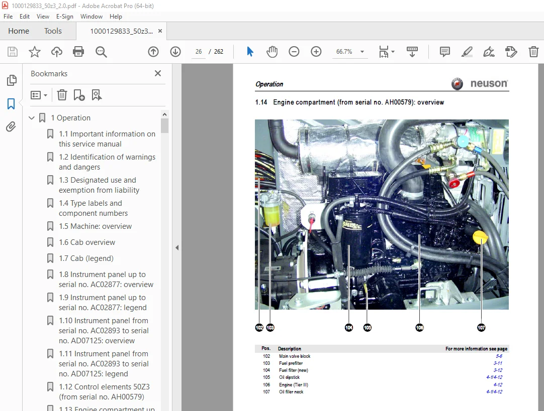
1 14 Engine compartment (from serial no AH00579): overview 26
1 15 Chassis overview 27
1 16 Tilting the cab 28
1 17 Summer/winter operation 30
Preheated fresh air 30
1 18 Turning the auxiliary hydraulics/boom swivel pedal around 31
2 Specifications 35
2 1 Chassis 35
2 2 Engine 35
Fuel injection pump 36
Engine capacities 36
Engine tightening torques 36
2 3 Hydraulic system 37
Auxiliary hydraulics oil flow 37
Screwable hose burst valve 38
2 4 Undercarriage and swivel unit 38
2 5 Stabiliser blade 38
2 6 Electric system 38
Fuse box in instrument panel 39
Main fuse box with relays underneath the cab 39
Relays 39
2 7 Noise levels 40
2 8 Vibration 40
2 9 Coolant compound table 40
2 10 Model-specific tightening torques 41
2 11 General tightening torques 41
Tightening torques for hydraulic screw connections (dry assembly) 41
Tightening torques for high-resistance screw connections 43
2 12 Dimensions model 50Z3 44
2 13 Lift capacity table 50Z3 45
2 14 Lift capacity table 50Z3 with long stick 46
2 15 Lift capacity table 50Z3 with counterweight 47
2 16 Lift capacity table 50Z3 with long stick and counterweight 48
2 17 Kinematics 49
2 18 Attachments 50
3 Maintenance 55
3 1 Fluids and lubricants 55
Additional oil change and filter replacement (hydraulics) 56
3 2 Maintenance label 57
Explanation of symbols on the maintenance label 57
3 3 Maintenance plan (overview) 59
3 4 Service package 62
Up to serial no : AD07125 62
From serial no : AH00579 62
3 5 Introduction 62
3 6 Fuel system 63
Specific safety instructions 63
Refuelling 63
Stationary fuel pumps 64
Diesel fuel specification 64
Bleeding the fuel system 64
Emptying the fuel tank 65
Fuel prefilter with water separator 65
Replacing the fuel filter 66
3 7 Engine lubrication system 67
Checking the oil level 67
Filling up engine oil 68
Changing engine oil 69
Replacing the engine oil filter cartridge 70
3 8 Cooling system 71
Specific safety instructions 71
Checking/filling up coolant 72
Draining coolant 73
3 9 Air filter 74
Replacing the filter 75
Functional check once a week of the dust valve 76
3 10 V-belt 77
Checking V-belt tension 77
Retightening the V-belt 78
Checking the V-belt of the air conditioning system 79
Tightening the V-belt of the air conditioning system 80
3 11 Pressure check 81
General 81
Checking pilot control pressure 81
Pressure check of variable displacement pump P1 82
Pressure check of variable displacement pump P2 83
Pressure check of gear pump P3 84
Secondary pressure limiting valve of the gear motor 84
Measuring ports: overview 85
Primary pressure limiting valves 85
3 12 Test report 86
3 13 Hydraulic system 89
Specific safety instructions 89
Checking the hydraulic oil level 90
Filling up hydraulic oil 91
Changing hydraulic oil 91
Monitoring the hydraulic oil reflux filter 92
Checking hydraulic pressure lines 93
3 14 Travelling drive 94
Checking the oil level and filling up oil 94
Draining oil 94
3 15 Chains 95
Checking chain tension 95
Setting the chains 96
3 16 Lubrication work 97
Stabiliser blade 97
Lubrication points on the swivelling console 97
Boom lubrication points 98
Lubrication points on the stick 98
Lubrication strip 99
Maintenance of attachments 99
3 17 Electric system 100
Specific safety instructions 100
Service and maintenance work at regular intervals 100
Instructions concerning specific components 101
Alternator 101
Battery 102
3 18 Cab 103
Replacing the cab filter 103
3 19 General maintenance work 104
Cleaning 104
General instructions for all areas of the machine 104
Inside the cab 105
Exterior of the machine 105
Engine compartment 105
Screw connections and attachments 105
Pivots and hinges 105
4 Engine 109
4 1 Engine 4TNV88-PNS (up to serial no AD07125): overview 109
4 2 Fuel system 111
4 3 Checking and adjusting valve clearance 112
4 4 Tightening order for cylinder head bolts 113
4 5 Checking the injection nozzles 114
Pressure check 114
4 6 Checking the nozzle jet 114
4 7 Injection time 115
Checking injection time 115
Setting injection time 115
Replacement of fuel injection pump 116
4 8 Adjusting engine revs 117
4 9 Compression 117
4 10 Checking the coolant thermostat 117
4 11 Checking the thermal switch 118
4 12 Oil pressure switch 118
4 13 Checking the coolant circuit 119
4 14 Engine 4TNV88-PNS (from serial no AH00579): overview 120
4 15 Fuel system 122
4 16 Removing the valve cover 123
4 17 Checking and adjusting valve clearance 123
4 18 Tightening order for cylinder head bolts 124
4 19 Checking the injection nozzles 125
Pressure check 125
4 20 Checking the nozzle jet 125
4 21 Injection time 126
Checking injection time 126
Setting injection time 127
Replacement of fuel injection pump 128
4 22 Adjusting engine revs 129
4 23 Compression 129
4 24 Checking the coolant thermostat 129
4 25 Checking the thermal switch 130
4 26 Oil pressure switch 130
4 27 Checking the coolant circuit 131
4 28 Engine trouble 131
SHB_50z3_EN_1000129833_Teil2 pdf 0
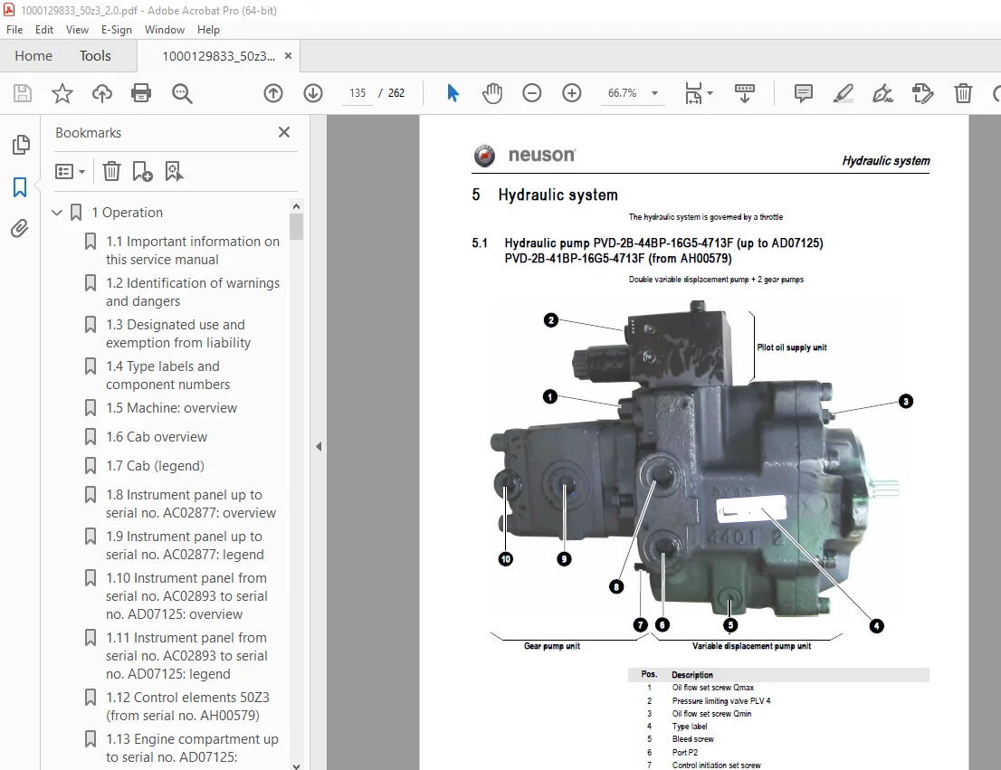
5 Hydraulic system 135
5 1 Hydraulic pump PVD-2B-44BP-16G5-4713F (up to AD07125) PVD-2B-41BP-16G5-4713F (from AH00579) 135
Pump unit: exploded view 137
Pilot oil supply unit 139
5 2 Main valve block 140
Ports 140
Legend 141
Main valve block diagram 142
Pressure limiting valves 143
Pump assignment 144
5 3 Drive counterbalancing system 145
Pump assignment for drive counterbalancing 145
Drive counterbalancing system with boom and right-hand side drive activation 146
5 4 Regeneration – stick section 147
5 5 Bucket pre-tension 147
5 6 Flow rate adjustment of auxiliary hydraulics 148
5 7 Pilot valves 149
Joystick 149
Pilot valve (driving) 151
Pilot valve for auxiliary hydraulics 153
Pilot valve for stabiliser blade 154
5 8 Valves 155
7/2 directional valve (changeover valve) 155
4/3 directional valve 156
Shuttle valve block 157
Changeover valve for SAE/ISO controls (option) 158
5 9 Travelling drive 159
Function 160
2nd speed range function 160
5 10 Swivel unit 163
Parking brake/multidisc brake function 164
5 11 Swivel joint 169
5 12 Breather filter 170
5 13 Troubleshooting in the hydraulic system 171
5 14 Hydraulics diagram A4 172
5 15 Hydraulics diagram (legend) 173
5 16 Hydraulics diagram 50Z3 A3 0
5 17 Options diagram 1 0
5 18 Options diagram 2 0
5 19 Main valve block diagram 50Z3 A3 0
6 Electric system 181
6 1 Ohm’s Law (current, voltage, resistance); power 181
6 2 Measuring equipment, measuring methods 181
6 3 Cable colour coding 183
6 4 Relays 183
Use, mode of function 183
6 5 Electric units 184
6 6 Fuse box in instrument panel 184
6 7 Main fuse box with relays 184
6 8 Relays 185
6 9 Socket 185
6 10 Joystick tip switches 186
Joystick (left) 186
Joystick (right) 186
6 11 Instrument panel overview 187
6 12 Switch overview (up to serial no AD07125) 188
6 13 Switch overview (from serial no AH00579) 188
6 14 Alternator 189
6 15 Starter 189
6 16 Wiring diagram A4 legend up to serial no AC02889 191
6 17 Wiring diagram A4 up to serial no AC02889 192
6 18 Wiring diagram A4 legend from serial no AC02890 193
6 19 Wiring diagram A4 from serial no AC02890 194
6 20 Engine – chassis wiring harness A4 (legend) 195
6 21 Engine – chassis wiring harness A4 196
6 22 Wiring harness 1000109630 switches A4 up to serial no AC02889: legend 197
6 23 Wiring harness 1000109630 switches A4 up to serial no AC02889 198
6 24 Wiring harness switches A4 from serial no AC02890 (legend) 199
6 25 Wiring harness switches A4 from serial no AC02890 200
6 26 Cab roof wiring harness 201
6 27 Armrest wiring harness 202
6 28 Boom working light wiring harness 203
6 29 Wiring diagram A3 up to serial no AC02889 (legend) 0
6 30 Wiring diagram A3 up to serial no AC02889 0
6 31 Wiring diagram A3 legend from serial no AC02890 0
6 32 Wiring diagram A3 from serial no AC02890 0
6 33 Engine – chassis wiring harness A3 (legend) 0
6 34 Engine – chassis wiring harness A3 0
6 35 Wiring harness 1000109630 switches A3 up to serial no AC02889 (legend) 0
6 36 Wiring harness 1000109630 switches A3 up to serial no AC02889 0
6 37 Wiring harness switches A3 from serial no AC02890 (legend) 0
6 38 Wiring harness switches A3 from serial no AC02890 0
6 39 Cab roof wiring harness A3 0
6 40 Armrest wiring harness A3 0
6 41 Boom working light wiring harness A3 0
7 Options 221
7 1 Air conditioning 221
Specific safety instructions 221
Specifications 221
Installation overview 222
Components 223
Filling up the air conditioning system 225
Maintenance 226
Troubleshooting 227
7 2 Air-suspension seat 229
Ports 229
7 3 Counterweight 229
Specifications 229
7 4 Long stick 229
Specifications 229
7 5 Control circuit (pipework) connections for grab 230
7 6 3rd control circuit connections 230
7 7 Auxiliary hydraulics connections 231
Quickhitch couplings 231
Attachments 232
7 8 Fuel-filling pump 233
Ports 234
7 9 Central lubrication system 235
Position 235
Ports 235
Function 236
Adjusting breaks and lubrication times 237
Repair in case of clogging 237
7 10 Service valve 239
Function 239
7 11 Safe load indicator D (safety valve for boom) 240
Position 240
Function 241
Wiring diagram 241
7 12 Safe load indicator F (safety valves for boom and stick) 242
Position 242
Function 243
Wiring diagram 244
7 13 3rd control circuit 245
Function 245
Diagram 245
7 14 Electric auxiliary hydraulics 246
Function 246
7 15 Auxiliary hydraulics shock cartridge 247
7 16 3rd control circuit shock cartridge 248
7 17 Drive interlock (antitheft protection) 249
Position 249
Disabling the drive interlock 249
Enabling the drive interlock 249
Programming 249
7 18 Quickhitch 251
7 19 Automatic idling speed feature 252
Function 252
Diagram 252
Wiring harness 253
7 20 Proportional controls 254
Function 254
Ports 254
Overview 255
Wiring harness 256
Control unit 256
Control valve plug assignment 257
Safety features 258
Measures to be taken in case of malfunctions 258
Diagnosis display 258
7 21 Automatic revs setting (Tier 3A from AH00579) 260
Function 260
Installation 261
DESCRIPTION:
Wacker Neuson 50Z3 Track Excavator Service Manual 1000129833 – PDF DOWNLOAD
Important information on this service manual:
- This service manual contains important information on how to service your machine safely,
correctly and economically. Therefore, it aims not only at new operators, but it also serves
as a reference for experienced ones. It helps to avoid dangerous situations and reduce
repair costs and downtimes. Furthermore, the reliability and the service life of the machine
will be increased by following the instructions in the service manual. - Careful and prudent working is the best way to avoid accidents!
- Operational safety and readiness of the machine do not only depend on your skill, but also
on maintenance and servicing of the machine. - Insist on using original spare parts when carrying out maintenance and repair work. This
ensures operational safety and readiness of your machine, and maintains its value. - Your Neuson After-Sales Service will be pleased to answer any further questions
regarding the machine or the service manual.
S.V 31/12/24