Wacker Neuson 5OZз Tracked excavators Service Manual – PDF DOWNLOAD
Original price was: $78.00.$24.95Current price is: $24.95.
Wacker Neuson 5OZз Tracked excavators Service Manual – PDF DOWNLOAD
Description
Wacker Neuson 5OZз Tracked excavators Service Manual – PDF DOWNLOAD
IMAGES PREVIEW OF THE MANUAL:
FILE DETAILS:
Wacker Neuson 5OZз Tracked excavators Service Manual – PDF DOWNLOAD
Operation
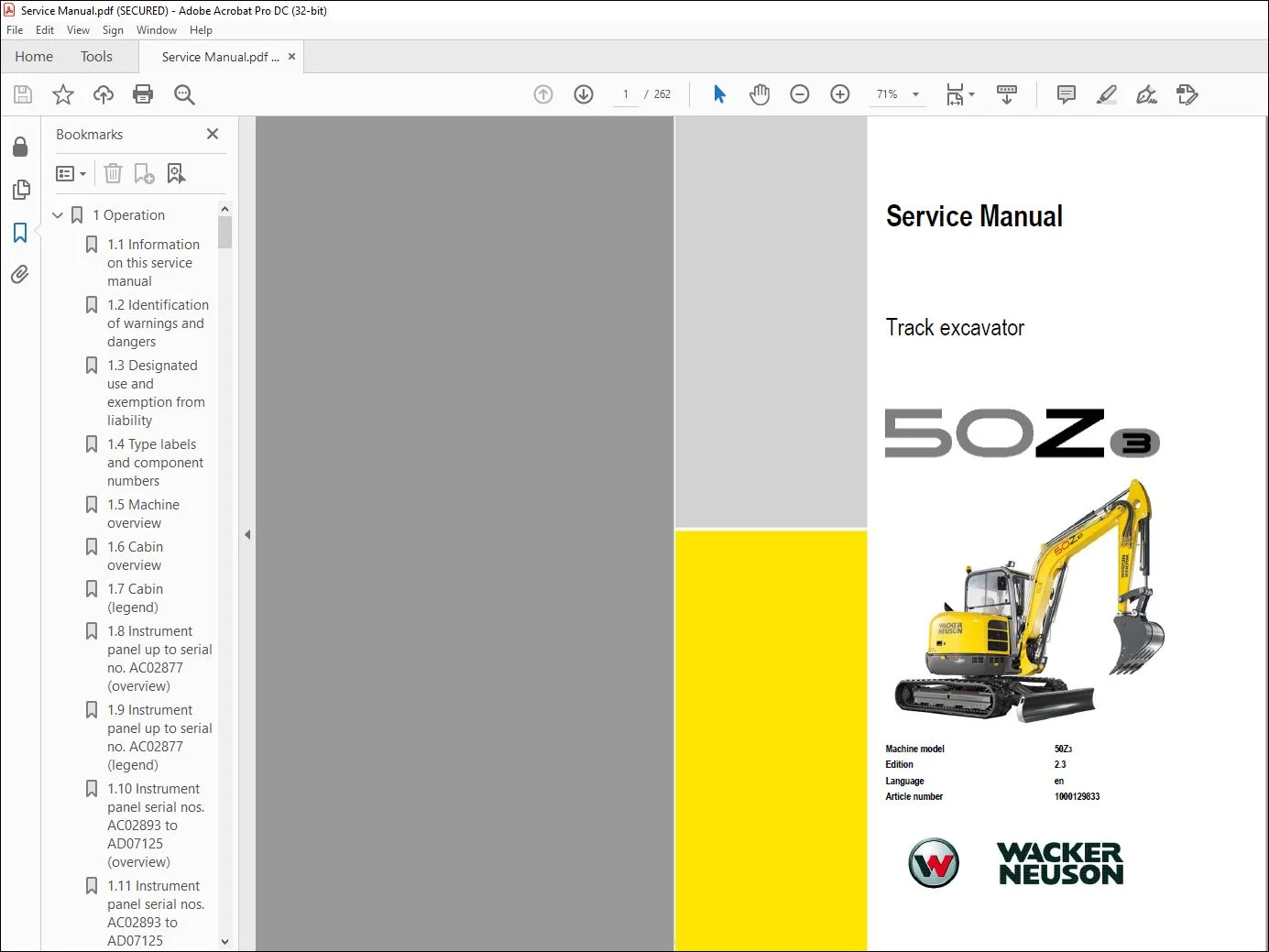
1.1 Information on this service manual
This service manual contains important information on how to service your machine safely,
correctly and economically. Therefore, it aims not only at new operators, but it also serves
as a reference for experienced ones. Your knowledge and skills will help to avoid
hazardous situations and reduce repair costs and downtimes. Furthermore, the reliability
and the service life of the machine will be increased by following the instructions in the
service manual.
Careful and prudent working is the best way to avoid accidents!
Operational safety and readiness of the machine do not only depend on your skill, but also
on maintenance and servicing of the machine.
Insist on using original spare parts when performing maintenance and repair work. This
ensures operational safety and readiness of your machine, and maintains its value.
Your Wacker Neuson After-Sales Service will be happy to answer any further questions
regarding the machine or the service manual
TABLE OF CONTENTS:
Wacker Neuson 5OZз Tracked excavators Service Manual – PDF DOWNLOAD
Operation
Information on this service manual ……………………………………………………………….. 1-2
Identification of warnings and dangers ………………………………………………………….. 1-3
Designated use and exemption from liability ………………………………………………….. 1-4
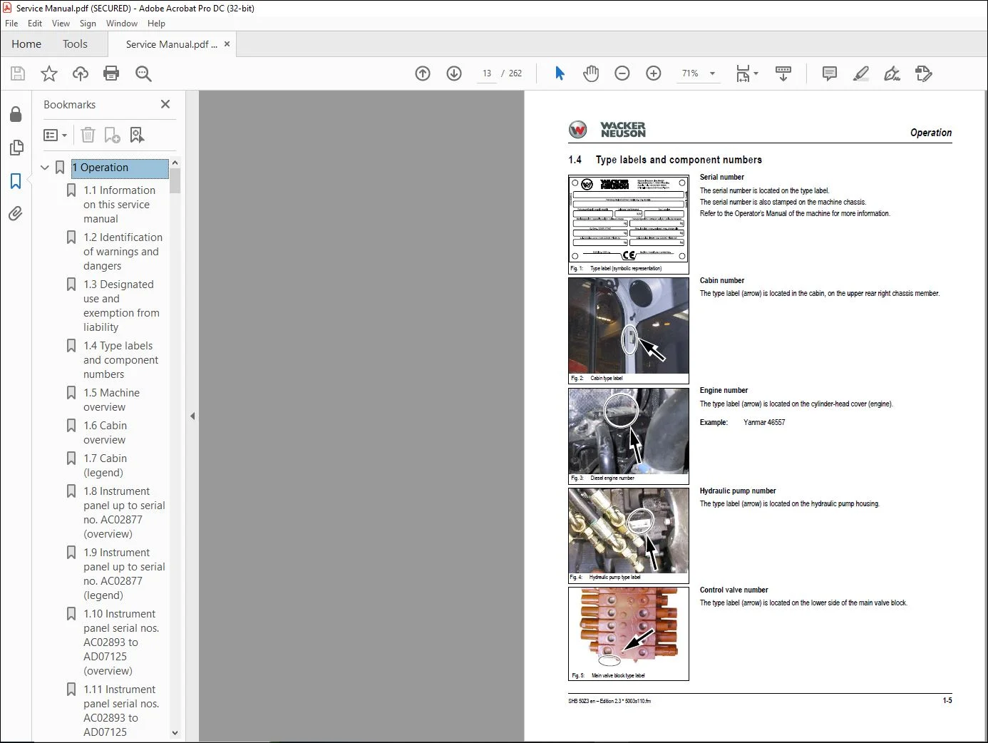
Type labels and component numbers ……………………………………………………………. 1-5
Machine overview ………………………………………………………………………………………. 1-7
Cabin overview ………………………………………………………………………………………….. 1-8
Cabin (legend) …………………………………………………………………………………………… 1-9
Instrument panel up to serial no. AC02877 (overview) …………………………………… 1-10
Instrument panel up to serial no. AC02877 (legend) ……………………………………… 1-11
Instrument panel serial nos. AC02893 to AD07125 (overview) ……………………….. 1-12
Instrument panel serial nos. AC02893 to AD07125 (legend) ………………………….. 1-13
Control elements 50Z3 (from serial no. AH00579) ………………………………………… 1-14
Engine compartment up to serial no. AD07125 (overview) …………………………….. 1-16
Engine compartment (from serial no. AH00579) (overview) ……………………………. 1-17
Chassis overview ……………………………………………………………………………………… 1-18
Raising/lowering the cabin …………………………………………………………………………. 1-19
Summer/winter operation …………………………………………………………………………… 1-21
Preheated fresh air ……………………………………………………………………………… 1-21
Turning the auxiliary hydraulics/boom swivel pedal around ……………………………. 1-22
Technical data
Chassis …………………………………………………………………………………………………….. 2-2
Engine ………………………………………………………………………………………………………. 2-2
Fuel injection pump ………………………………………………………………………………. 2-4
Engine capacities …………………………………………………………………………………. 2-4
Engine tightening torques ………………………………………………………………………. 2-4
Hydraulic system ……………………………………………………………………………………….. 2-5
Auxiliary hydraulics oil flow …………………………………………………………………….. 2-5
Screwable hose burst valve ……………………………………………………………………. 2-6
Travel gear and swivel unit ………………………………………………………………………….. 2-6
Stabilizer blade ………………………………………………………………………………………….. 2-6
Electrical system ………………………………………………………………………………………… 2-6
Fuse box in instrument panel …………………………………………………………………. 2-7
Main fuse box with relays underneath the cabin ……………………………………….. 2-7
Relays …………………………………………………………………………………………………. 2-7
Noise levels ………………………………………………………………………………………………. 2-8
Vibration ……………………………………………………………………………………………………. 2-8
Coolant compound table ……………………………………………………………………………… 2-8
Model-specific tightening torques …………………………………………………………………. 2-9
Tightening torques for hydraulic threaded fittings (dry assembly) ………………… 2-9
Tightening torques for high-resistance threaded fittings ……………………………. 2-11
Dimensions model 50Z3 ……………………………………………………………………………. 2-13
Lift capacity tables ……………………………………………………………………………………. 2-14
Kinematics ………………………………………………………………………………………………. 2-14
Maintenance
Fluids and lubricants …………………………………………………………………………………… 3-2
Additional oil change and filter replacement (hydraulic system) …………………… 3-3
Maintenance label ………………………………………………………………………………………. 3-4
Explanation of symbols on the maintenance label …………………………………….. 3-4
Maintenance plan (overview) ……………………………………………………………………….. 3-6
Introduction ……………………………………………………………………………………………… 3-11
Fuel system …………………………………………………………………………………………….. 3-12
Specific safety instructions …………………………………………………………………… 3-12
Refueling …………………………………………………………………………………………… 3-12
Table of contents
I-2 SHB 50Z3 en – Edition 2.3 * 5003s11IVZ.fm
Table of contents
Stationary fuel pumps ………………………………………………………………………….. 3-13
Diesel fuel specification ……………………………………………………………………….. 3-13
Bleeding the fuel system ………………………………………………………………………. 3-13
Emptying the fuel tank …………………………………………………………………………. 3-14
Fuel prefilter with water separator …………………………………………………………. 3-14
Replacing the fuel filter ………………………………………………………………………… 3-15
Engine lubrication system ………………………………………………………………………….. 3-16
Checking the oil level …………………………………………………………………………… 3-16
Adding engine oil ………………………………………………………………………………… 3-17
Changing engine oil …………………………………………………………………………….. 3-18
Replacing the engine-oil filter cartridge ………………………………………………….. 3-19
Cooling system ………………………………………………………………………………………… 3-20
Specific safety instructions …………………………………………………………………… 3-20
Checking the coolant level/adding coolant ……………………………………………… 3-21
Draining coolant ………………………………………………………………………………….. 3-23
Air filter ……………………………………………………………………………………………………. 3-24
Replacing the filter ………………………………………………………………………………. 3-25
Functional check once a week of the dust valve ……………………………………… 3-25
V-belt ………………………………………………………………………………………………………. 3-27
Checking V-belt tension ……………………………………………………………………….. 3-27
Retightening the V-belt ………………………………………………………………………… 3-28
Checking the V-belt of the air conditioning system …………………………………… 3-29
Tightening the V-belt of the air conditioning system …………………………………. 3-30
Pressure check ………………………………………………………………………………………… 3-31
General ……………………………………………………………………………………………… 3-31
Checking pilot control pressure …………………………………………………………….. 3-31
Pressure check of variable displacement pump P1 ………………………………….. 3-32
Pressure check of variable displacement pump P2 ………………………………….. 3-33
Pressure check of gear pump P3 ………………………………………………………….. 3-34
Secondary pressure limiting valve of the gear motor ………………………………… 3-34
Measurement connections (overview) ……………………………………………………. 3-36
Primary pressure limiting valves ……………………………………………………………. 3-36
Test report ……………………………………………………………………………………………….. 3-37
Hydraulic system ………………………………………………………………………………………. 3-40
Specific safety instructions …………………………………………………………………… 3-40
Checking the hydraulic oil level …………………………………………………………….. 3-40
Adding hydraulic oil ……………………………………………………………………………… 3-42
Changing hydraulic oil …………………………………………………………………………. 3-42
Monitoring the hydraulic oil return filter …………………………………………………… 3-43
Checking hydraulic pressure lines …………………………………………………………. 3-44
Traveling drive …………………………………………………………………………………………. 3-44
Checking the oil level and adding oil ……………………………………………………… 3-45
Draining oil …………………………………………………………………………………………. 3-45
Tracks …………………………………………………………………………………………………….. 3-46
Checking track tension ………………………………………………………………………… 3-46
Setting the tracks ………………………………………………………………………………… 3-46
Overview of lubrication points …………………………………………………………………….. 3-48
Parking the machine ……………………………………………………………………………. 3-49
Lubrication points on the boom, bucket and stick cylinders ……………………….. 3-49
Lubrication points on the boom and stick ……………………………………………….. 3-50
Joint rod lubrication point ……………………………………………………………………… 3-51
Lubrication points on the stabilizer blade and stabilizer blade cylinder ……….. 3-52
Lubrication points on the swiveling cylinder and swiveling console …………….. 3-52
Lubrication points on live ring (ball bearing) ……………………………………………. 3-53
Lubrication points of live ring (teeth) ………………………………………………………. 3-54
Powertilt lubrication points (option) ………………………………………………………… 3-55
Lubrication points of hydraulic quickhitch (option) ……………………………………. 3-55
SHB 50Z3 en – Edition 2.3 * 5003s11IVZ.fm I-3
Table of contents
Control lever base lubrication points ……………………………………………………… 3-56
VDS lubrication points (option) ……………………………………………………………… 3-56
Maintenance of attachments ………………………………………………………………… 3-56
Electrical system ………………………………………………………………………………………. 3-57
Specific safety instructions …………………………………………………………………… 3-57
Servicing and maintenance at regular intervals ……………………………………….. 3-57
Instructions concerning specific components ………………………………………….. 3-57
Alternator …………………………………………………………………………………………… 3-58
Battery ……………………………………………………………………………………………………. 3-59
Battery charge condition ………………………………………………………………………. 3-59
Charging the battery ……………………………………………………………………………. 3-59
Replacing the battery …………………………………………………………………………… 3-59
Cabin ……………………………………………………………………………………………………… 3-60
Replacing the cabin filter ……………………………………………………………………… 3-60
General maintenance ……………………………………………………………………………….. 3-61
Cleaning ……………………………………………………………………………………………. 3-61
General instructions for all areas of the machine …………………………………….. 3-61
Inside the cabin ………………………………………………………………………………….. 3-62
Exterior of the machine ………………………………………………………………………… 3-62
Engine compartment …………………………………………………………………………… 3-62
Threaded fittings and attachments ………………………………………………………… 3-62
Pivots and hinges ……………………………………………………………………………….. 3-63
Engine
Engine 4TNV88-PNS (up to serial no. AD07125) ……………………………………………. 4-2
Fuel system ………………………………………………………………………………………………. 4-4
Checking and adjusting valve clearance ……………………………………………………….. 4-5
Tightening order for cylinder head bolts ………………………………………………………… 4-6
Checking the injection nozzles …………………………………………………………………….. 4-7
Pressure check …………………………………………………………………………………….. 4-7
Checking the nozzle jet ……………………………………………………………………………….. 4-7
Injection time ……………………………………………………………………………………………… 4-8
Checking injection time ………………………………………………………………………….. 4-8
Setting injection time …………………………………………………………………………….. 4-8
Replacement of fuel injection pump ………………………………………………………… 4-9
Adjusting engine speed …………………………………………………………………………….. 4-10
Compression ……………………………………………………………………………………………. 4-10
Checking the coolant thermostat ………………………………………………………………… 4-10
Checking the thermal switch ………………………………………………………………………. 4-11
Oil pressure switch …………………………………………………………………………………… 4-11
Checking the coolant circuit ……………………………………………………………………….. 4-12
Engine 4TNV88-PNS (from serial no. AH00579) …………………………………………… 4-13
Fuel system …………………………………………………………………………………………….. 4-15
Removing the cylinder-head cover ……………………………………………………………… 4-16
Checking and adjusting valve clearance ……………………………………………………… 4-16
Tightening order for cylinder head bolts ………………………………………………………. 4-17
Checking the injection nozzles …………………………………………………………………… 4-18
Pressure check …………………………………………………………………………………… 4-18
Checking the nozzle jet ……………………………………………………………………………… 4-18
Injection time ……………………………………………………………………………………………. 4-19
Checking injection time ………………………………………………………………………… 4-19
Setting injection time …………………………………………………………………………… 4-20
Replacement of fuel injection pump ………………………………………………………. 4-21
Adjusting engine speed …………………………………………………………………………….. 4-22
Compression ……………………………………………………………………………………………. 4-22
Checking the coolant thermostat ………………………………………………………………… 4-23
Checking the thermal switch ………………………………………………………………………. 4-23
I-4 SHB 50Z3 en – Edition 2.3 * 5003s11IVZ.fm
Table of contents
Oil pressure switch ……………………………………………………………………………………. 4-24
Checking the coolant circuit ……………………………………………………………………….. 4-24
Engine malfunctions ………………………………………………………………………………….. 4-25
Hydraulic system
Hydraulic pump PVD-2B-44BP-16G5-4713F (up to AD07125)
PVD-2B-41BP-16G5-4713F (from AH00579) …………………………………………………. 5-2
Pump unit: exploded view ………………………………………………………………………. 5-4
Pilot oil supply unit ………………………………………………………………………………… 5-6
Main valve block ………………………………………………………………………………………… 5-7
Connections …………………………………………………………………………………………. 5-7
Legend ………………………………………………………………………………………………… 5-8
Main valve block diagram ………………………………………………………………………. 5-9
Pressure limiting valves ……………………………………………………………………….. 5-10
Pump assignment ……………………………………………………………………………….. 5-11
Drive counterbalancing system …………………………………………………………………… 5-12
Pump assignment for drive counterbalancing ………………………………………….. 5-12
Drive counterbalancing system with boom and right-hand side drive activation …..
5-13
Regeneration – stick section ………………………………………………………………………. 5-14
Bucket pre-tension ……………………………………………………………………………………. 5-14
Flow rate adjustment of auxiliary hydraulics …………………………………………………. 5-15
Pilot valves ………………………………………………………………………………………………. 5-16
Joystick ……………………………………………………………………………………………… 5-16
Drive pilot valve (up to serial no. WNCE0504APAL00176) ……………………….. 5-18
Drive pilot valve (from serial no. WNCE0504APAL00177) ………………………… 5-20
Pilot valve for auxiliary hydraulics ………………………………………………………….. 5-21
Stabilizer blade pilot valve ……………………………………………………………………. 5-22
Valves …………………………………………………………………………………………………….. 5-23
7/2 directional valve (changeover valve) ………………………………………………… 5-23
4/3 directional valve …………………………………………………………………………….. 5-24
Shuttle valve block ………………………………………………………………………………. 5-25
Changeover valve for SAE/ISO controls (option) …………………………………….. 5-26
Traveling drive …………………………………………………………………………………………. 5-27
Trasmital drive (up to serial no. AH01729) ……………………………………………… 5-27
Function …………………………………………………………………………………………….. 5-28
2nd speed range function …………………………………………………………………….. 5-28
Kayaba drive (serial nos. AH01730 to AJ04340) ……………………………………… 5-31
Trasmital drive (from serial no. AJ04341) ……………………………………………….. 5-34
Function …………………………………………………………………………………………….. 5-35
2nd speed range function …………………………………………………………………….. 5-35
Swivel unit ……………………………………………………………………………………………….. 5-38
Parking brake/multidisc brake function …………………………………………………… 5-39
Swivel joint ………………………………………………………………………………………………. 5-44
Breather filter …………………………………………………………………………………………… 5-45
Malfunctions in the hydraulic system …………………………………………………………… 5-46
Hydraulics diagram (legend) ………………………………………………………………………. 5-48
Hydraulics diagram 50Z3 (serial nos. AC02471 to AD07125) …………………………. 5-49
Hydraulics diagram 50Z3 options (serial nos. AC02471 to AD07125) ………………. 5-50
Hydraulics diagram 50Z3 (serial nos. AH00579 to AH00917) …………………………. 5-51
Hydraulics diagram 50Z3 options (serial nos. AH00579 to AH00917) ………………. 5-52
Hydraulics diagram 50Z3 (from serial no. AH00918) ……………………………………… 5-53
Hydraulics diagram 50Z3 options (from serial no. AH00918) ………………………….. 5-54
Hydraulics diagram 50Z3 (from serial no. AJ03401) ………………………………………. 5-55
Proportional controls diagram …………………………………………………………………….. 5-56
Main valve block diagram 50Z3 A3 ……………………………………………………………… 5-57
Electrical system
SHB 50Z3 en – Edition 2.3 * 5003s11IVZ.fm I-5
Table of contents
Ohm’s Law (current, voltage, resistance); power ……………………………………………. 6-2
Measuring equipment, measuring methods ……………………………………………………. 6-2
Cable color coding ……………………………………………………………………………………… 6-3
Relays ………………………………………………………………………………………………………. 6-4
Use, mode of function ……………………………………………………………………………. 6-4
Electric units ……………………………………………………………………………………………… 6-4
Fuse box in instrument panel ……………………………………………………………………….. 6-4
Main fuse box with relays ……………………………………………………………………………. 6-5
Relays ………………………………………………………………………………………………………. 6-5
Socket ………………………………………………………………………………………………………. 6-5
Control lever push button …………………………………………………………………………….. 6-6
Control lever on the left …………………………………………………………………………. 6-6
Control lever on the right ……………………………………………………………………….. 6-6
Instrument panel overview …………………………………………………………………………… 6-7
Switches up to serial no. AD07125 (overview) ……………………………………………….. 6-8
Switches from serial no. AH00579 (overview) ………………………………………………… 6-8
Alternator ………………………………………………………………………………………………….. 6-9
Starter ………………………………………………………………………………………………………. 6-9
Wiring diagram legend (up to serial no. AC02889) ………………………………………… 6-12
Wiring diagram (up to serial no. AC02889) …………………………………………………… 6-13
Wiring diagram legend (from serial no. AC02890) …………………………………………. 6-14
Wiring diagram (from serial no. AC02890) …………………………………………………… 6-15
Engine/chassis wiring harness legend (up to serial no. AJ02831) …………………… 6-16
Engine/chassis wiring harness (up to serial no. AJ02831) ……………………………… 6-17
Engine/chassis wiring harness legend (from serial no. AJ02832) ……………………. 6-18
Engine/chassis wiring harness (from serial no. AJ02832) ………………………………. 6-19
Switches wiring harness legend (up to serial no. AC02889) …………………………… 6-20
Switches wiring harness (up to serial no. AC02889) ……………………………………… 6-21
Switches wiring harness legend (from serial no. AC02890) ……………………………. 6-22
Switches wiring harness (from serial no. AC02890) ………………………………………. 6-23
Cabin roof wiring harness ………………………………………………………………………….. 6-24
Armrest wiring harness ……………………………………………………………………………… 6-25
Boom working light wiring harness ……………………………………………………………… 6-26
Rotating beacon wiring harness …………………………………………………………………. 6-27
Options
Air conditioning ………………………………………………………………………………………….. 7-2
Specific safety instructions …………………………………………………………………….. 7-2
Technical data ……………………………………………………………………………………… 7-2
Installation overview ……………………………………………………………………………… 7-3
Components ………………………………………………………………………………………… 7-4
Filling up the air conditioning system ……………………………………………………….. 7-6
Maintenance ………………………………………………………………………………………… 7-7
Troubleshooting ……………………………………………………………………………………. 7-8
Air-suspension seat ………………………………………………………………………………….. 7-10
Connections ……………………………………………………………………………………….. 7-10
Counterweight ………………………………………………………………………………………….. 7-10
Technical data ……………………………………………………………………………………. 7-10
Long stick ………………………………………………………………………………………………… 7-10
Technical data ……………………………………………………………………………………. 7-10
Control circuit (pipework) connections for grab …………………………………………….. 7-11
3rd control circuit connections ……………………………………………………………………. 7-11
Auxiliary hydraulics connections …………………………………………………………………. 7-12
Quickhitch couplings ……………………………………………………………………………. 7-12
Attachments ……………………………………………………………………………………….. 7-13
Fuel-filling pump ………………………………………………………………………………………. 7-14
Connections ……………………………………………………………………………………….. 7-15
I-6 SHB 50Z3 en – Edition 2.3 * 5003s11IVZ.fm
Table of contents
Central lubrication system ………………………………………………………………………….. 7-16
Position ……………………………………………………………………………………………… 7-16
Connections ……………………………………………………………………………………….. 7-16
Function …………………………………………………………………………………………….. 7-17
Adjusting breaks and lubrication times …………………………………………………… 7-18
Repair in case of clogging ……………………………………………………………………. 7-18
Service valve ……………………………………………………………………………………………. 7-20
Function …………………………………………………………………………………………….. 7-20
Safe load indicator D (safety valve for boom) ……………………………………………….. 7-21
Position ……………………………………………………………………………………………… 7-21
Function …………………………………………………………………………………………….. 7-22
Wiring diagram ……………………………………………………………………………………. 7-22
Safe load indicator F (safety valves for boom and stick) ………………………………… 7-23
Position ……………………………………………………………………………………………… 7-23
Function …………………………………………………………………………………………….. 7-24
Wiring diagram ……………………………………………………………………………………. 7-25
3rd control circuit ………………………………………………………………………………………. 7-26
Function …………………………………………………………………………………………….. 7-26
Diagram …………………………………………………………………………………………….. 7-26
Electric auxiliary hydraulics ………………………………………………………………………… 7-27
Function …………………………………………………………………………………………….. 7-27
Auxiliary hydraulics shock cartridge …………………………………………………………….. 7-28
3rd control circuit shock cartridge ……………………………………………………………….. 7-29
Drive interlock (antitheft protection) …………………………………………………………….. 7-30
Position ……………………………………………………………………………………………… 7-30
Disabling the drive interlock ………………………………………………………………….. 7-30
Enabling the drive interlock …………………………………………………………………… 7-30
Programming ……………………………………………………………………………………… 7-30
Quickhitch ……………………………………………………………………………………………….. 7-32
Automatic idling speed feature ……………………………………………………………………. 7-33
Function …………………………………………………………………………………………….. 7-33
Diagram …………………………………………………………………………………………….. 7-33
Wiring harness ……………………………………………………………………………………. 7-34
Proportional controls …………………………………………………………………………………. 7-35
Function …………………………………………………………………………………………….. 7-35
Connections ……………………………………………………………………………………….. 7-35
Overview ……………………………………………………………………………………………. 7-36
Wiring harness ……………………………………………………………………………………. 7-37
Control unit ………………………………………………………………………………………… 7-37
Control unit connector assignment ………………………………………………………… 7-38
Safety features ……………………………………………………………………………………. 7-39
Measures to be taken in case of malfunctions …………………………………………. 7-39
Diagnosis display ………………………………………………………………………………… 7-39
Automatic engine speed setting (Tier 3A from AH00579) ……………………………….. 7-41
Function …………………………………………………………………………………………….. 7-41
Installation ………………………………………………………………………………………….. 7-42
Telematic ………………………………………………………………………………………………… 7-43
Connections ……………………………………………………………………………………….. 7-43
Functional check/diode ………………………………………………………………………… 7-43
Contact us: [email protected]
PLEASE NOTE:
- This is the SAME exact manual used by your dealers to fix your vehicle.
- The same can be yours in the next 2-3 mins as you will be directed to the download page immediately after paying for the manual.
- Any queries / doubts regarding your purchase, please feel free to contact [email protected]
S.M