Wacker Neuson 6001 & 6001H Dumper Service Manual 1000163656 – PDF DOWNLOAD
Original price was: $89.95.$29.95Current price is: $29.95.
Wacker Neuson 6001 & 6001H Dumper Service Manual 1000163656 – PDF DOWNLOAD
Description
Wacker Neuson 6001 & 6001H Dumper Service Manual 1000163656 – PDF DOWNLOAD
FILE DETAILS:
Wacker Neuson 6001 & 6001H Dumper Service Manual 1000163656 – PDF DOWNLOAD
Language : English
Pages : 310
Downloadable : Yes
File Type : PDF
Size: 20.6 MB
IMAGES PREVIEW OF THE MANUAL:
Questions? Email us: [email protected]
DESCRIPTION:
Wacker Neuson 6001 & 6001H Dumper Service Manual 1000163656 – PDF DOWNLOAD
This service manual contains important information on how to service your machine safely, correctly and economically. Therefore, it aims not only at new operators, but it also serves as a reference for experienced ones.
- After you will have read this service manual, your knowledge will help you avoid danger and reduce repair costs and downtimes. You will thereby increase the reliability and the service life of the machine.
- Careful and prudent working is the best way to avoid accidents! Operational safety and readiness of the machine do not only depend on your skill, but also on maintenance and servicing of the machine.
- Insist on using original spare parts when performing maintenance and repair work. This ensures operational safety and readiness of the dumper, and maintains its value. Your Wacker Neuson dealer will be pleased to answer any further questions regarding the machine or the service manual.
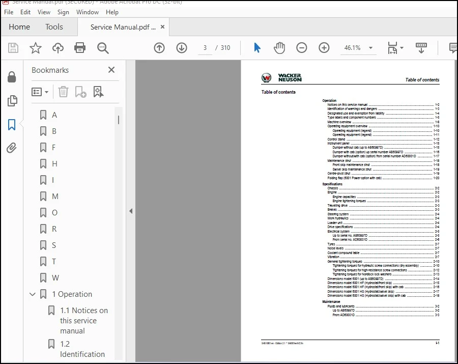
TABLE OF CONTENTS:
Wacker Neuson 6001 & 6001H Dumper Service Manual 1000163656 – PDF DOWNLOAD
A 9
B 9
F 9
H 9
I 9
M 9
O 9
R 9
S 9
T 9
W 9
1 Operation 12
1 1 Notices on this service manual 12
1 2 Identification of warnings and dangers 13
1 3 Designated use and exemption from liability 14
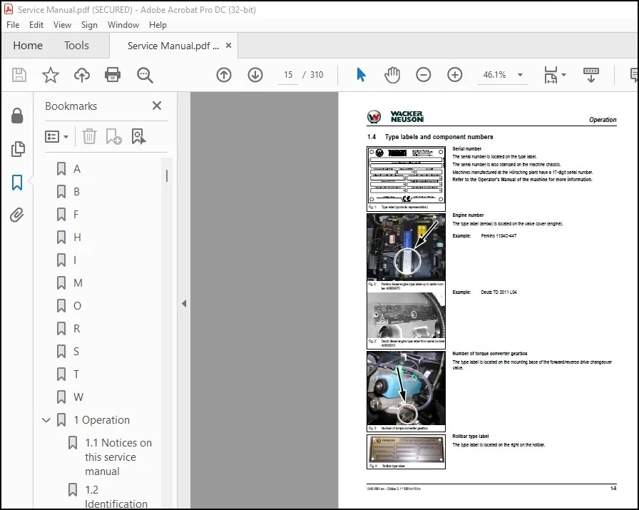
1 4 Type labels and component numbers 15
1 5 Machine overview 18
1 6 Operating equipment overview 20
Operating equipment (legend) 20
Operating equipment (legend) 21
1 7 Control stand 22
1 8 Instrument panel 25
Dumper without cab (up to AB60997D) 25
Dumper with cab (option) up serial number AB60997D 26
Dumper without/with cab (option) from serial number AD60001D 27
1 9 Maintenance strut 28
Front skip maintenance strut 28
Swivel skip maintenance strut 29
1 10 Centre-pivot strut 29
1 11 Folding flap (6001 Power option with cab) 30
2 Specifications 32
2 1 Chassis 32
2 2 Engine 32
Engine capacities 33
Engine tightening torques 33
2 3 Travelling drive 33
2 4 Brakes 33
2 5 Steering system 34
2 6 Work hydraulics 34
2 7 Loader unit 34
2 8 Drive specifications 34
2 9 Electrical system 35
Up to serial no AB60997D 35
From serial no AD60001D 36
2 10 Tyres 37
2 11 Noise levels 37
2 12 Coolant compound table 37
2 13 Vibration 37
2 14 General tightening torques 40
Tightening torques for hydraulic screw connections (dry assembly) 40
Tightening torques for high-resistance screw connections 42
Tightening torques for Nordlock lock washers 43
2 15 Dimensions model 6001 (up to AB60997D) 44
2 16 Dimensions model 6001 HF (Hydrostat/front skip) 45
2 17 Dimensions model 6001 HF (Hydrostat/front skip) with cab 46
2 18 Dimensions model 6001 HS (Hydrostat/swivel skip) 47
2 19 Dimensions model 6001 HS (Hydrostat/swivel skip) with cab 48
3 Maintenance 50
3 1 Fluids and lubricants 50
Up to AB60997D 50
From AD60001D 51
3 2 Maintenance plan (overview) 53
3 3 Service package 56
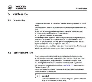
3 4 Introduction 56
3 5 Fuel system 57
Specific safety instructions 57
Refuelling 57
Stationary fuel pumps 58
Diesel fuel specification 58
Bleeding the fuel system 59
Bleeding the fuel system from AD60001D 59
Fuel prefilter with water separator (up to serial no AB60997D) 60
Replacing the fuel filter 61
3 6 Engine lubrication system 62
Checking the oil level 62
Adding engine oil 63
Changing engine oil 64
Replacing the engine oil filter cartridge 65
3 7 Cooling system 66
Specific safety instructions 66
Checking the coolant level/adding coolant 67
Draining coolant 69
3 8 Air filter 70
Weekly check of air filter for dirt 70
Replacing the filter 71
Functional check once a week of the dust valve 72
3 9 V-belt 72
Checking V-belt tension 72
Retightening the V-belt 73
3 10 Gearbox lubrication system (up to AB60997D) 75
Check the oil level 75
Adding gearbox oil 76
Changing gearbox oil 77
Replacing the gearbox oil filter cartridge 78
3 11 Hydraulic system 79
Specific safety instructions 79
Checking the hydraulic oil level 80
Adding hydraulic oil 80
Changing hydraulic oil 81
Monitoring the hydraulic oil return filter 81
Replacing the hydraulic oil return filter 81
Checking hydraulic pressure lines 82
3 12 Lubrication points 83
Maintenance of folding flap, 6001 Power with cab 84
3 13 Tyre maintenance and checks 84
Checks once a day 84
Checks once a week 84
3 14 Changing wheels 85
Removing 85
Installing 85
3 15 Axles 86
Checking the oil level and adding oil 86
Draining oil 86
3 16 Electrical system 87
Specific safety instructions 87
Service and maintenance work at regular intervals 87
Instructions concerning specific components 88
Alternator 88
3 17 Battery 89
3 18 General maintenance work 91
Cleaning 91
General instructions for all areas of the machine 91
Exterior of the machine 92
Engine compartment 92
Screw connections and attachments 92
Pivots and hinges 92
3 19 Test report 6001 93
4 Engine 98
4 1 Engine overview 1104 C-44 98
4 2 Engine overview 1104 C-44T 100
4 3 Fuel system 102
Checking and adjusting valve clearance 103
Tightening order for cylinder head bolts 104
4 4 Checking the injection nozzles 105
Pressure check 105
Checking the nozzle jet 106
Injection time 106
4 5 Adjusting engine speed 107
4 6 Compression 107
4 7 Checking the coolant thermostat 108
Checking the thermal switch 108
4 8 Oil pressure switch 109
4 9 Checking the coolant circuit 109
4 10 TD 2011 L04 W engine overview (from serial no AD60001D) 110
4 11 Fuel system 113
4 12 Crankcase vent 114
4 13 Checking and adjusting valve clearance 115
4 14 Checking and adjusting the fuel injectors 116
4 15 Adjusting engine speed 118
4 16 Spring reset of engine speed control 6001 Power (from serial no EA3127) 118
4 17 Compression pressure 119
4 18 Removing/installing the cylinder head 120
Intake/exhaust manifold 123
4 19 Replacing the injection pump/setting fuel injection time 123
4 20 Oil pressure switch 127
4 21 Engine trouble 128
5 Travelling drive 132
5 1 Torque converter gearbox SS620 (from serial no AA60004D to AB60997D) 132
Section SS 600 136
5 2 Torque converter gearbox PS750 (option) from serial no AB60078D to AB60997D 137
Section PS 750 141
Oil level check on torque converter gearbox 143
5 3 Cardan shaft 143
5 4 Transfer gearbox (from serial no AA60004D to AB60997D) 144
5 5 Travelling drive diagram (up to serial no AB60997D) 146
5 6 Test instructions SS620 147
Check: converter pressure 147
Check: main pressure 148
Check: clutch pressure (forward & reverse) 149
Check: oil cooler flow capacity (in neutral position) 150
5 7 Test instructions PS750 151
Checking converter pressure (up to AB60997D) 151
Checking main pressure (up to AB60997D) 152
Check: oil cooler flow capacity (in neutral position) up to AB60997D 153
5 8 Hydrostat (from serial no AD60001D) 154
Automotive driving 154
Closed circuit with inching valve 154
Variant 154
5 9 Variable displacement motor A6VM160HA2U1 and A6VM140HA1R1 155
High-pressure-sensitive regulation 155
Travelling drive overview 156
5 10 Replacing external components (hydraulic motor) 158
Replacing the rotary shaft lip seal 159
Control unit 160
Sealing the cover 162
5 11 Hydraulic motor settings 164
Checking control initiation 164
Control initiation test instructions 165
5 12 Variable displacement pump A4VG71DA1D8 (from serial no AD60001D) 166
Variable displacement pump: diagram 168
Variable displacement pump: diagram 169
Power train overview 170
Connecting plate with valves 171
5 13 Inching valve 172
5 14 Hydraulic pump test instructions (from AD60001D) 173
High pressure check 173
Checking boost pressure 173
Checking setting pressure 174
Control initiation and end 174
5 15 Replacing components (hydraulic pump) 175
Replacing the rotary shaft lip seal 175
Seals 176
Auxiliary (boost) pump 179
Replacing the inching valve 179
5 16 Towing 181
Safety instructions 181
Towing (from AD60001D) 181
Opening the high-pressure circuit 181
Towing (up to AB60997D) 182
6 Axles 184
6 1 Axle type label 184
6 2 Drain, filler and check plug 185
Transfer gearbox 186
6 3 Axle mounting 187
6 4 Tightening torques 188
Wheel screws 188
General tightening torques (Nm) 188
6 5 Cardan shaft 189
6 6 Transfer gearbox (up to serial no AB60997D) 190
6 7 Semiaxles (up to serial no AB60997D) 192
6 8 Wheel hub 199
6 9 Brakes (up to serial no AB60997D) 200
6 10 Differential (up to serial no AB60997D) 206
6 11 Drive housing (from serial no AD60001D) 208
6 12 Semiaxles (from serial no AD60001D) 210
Rear axle 212
6 13 Brakes (from serial no AD60001D) 214
6 14 Differential (from serial no AD60001D) 216
6 15 Dismantling and assembling (rear axle from AD60001D) 217
Dismantling the planetary drive and the semiaxle 217
Assembling the planetary drive and the semiaxle 219
Dismantling the differential 222
Assembling the differential 224
Removing the bevel gear 226
Installing the bevel gear 227
6 16 Special tools 232
7 Brakes 234
7 1 Brake circuit (up to serial no AB60997D) 234
7 2 Brake circuit (from serial no AD60001D) 236
Service brake 236
Parking brake 237
Brakes 238
7 3 Check wear and replace the brake discs (from AD60001D): 239
Removing the brake: 239
Assembling the brake: 240
7 4 Mechanical parking brake (from AD60001D): 243
Removing and installing the parking brake 243
Parking brake 235
8 Steering system 248
8 1 Steering circuit 248
Up to serial no AB60997D 248
From serial no AD60001D 249
8 2 Steering unit: diagram 250
Up to serial no AB60997D 250
From serial no AD60001D 250
Function 251
8 3 Steering unit connections 251
Up to serial no AB60997D 251
From serial no AD60001D 252
8 4 Exploded view of steering unit (up to serial no AB60997D) 253
Priority valve overview 253
Priority valve (legend) 253
9 Hydraulic system 256
9 1 Gear pump 256
9 2 Manual spool connections: overview 257
Swivel skip spool (up to serial no AB60997D) 257
Swivel skip spool (from serial no AD60001D) 258
Front skip spool (up to serial no AB60997D) 259
Front skip spool (serial nos AD60001D to EA03236) 260
Front skip spool (from serial no EA03237) 261
Overview of ports 261
9 3 Dumping the skip: hydraulic diagram 262
Up to serial no AB60997D 262
6001 AB60165D – AB60680D 263
From serial no AD60001D 264
9 4 Swivelling the skip (option): hydraulics diagram 265
Up to serial no AB60997D 265
From serial no AD60001D 266
9 5 Test instructions 267
Checking the work hydraulics on a swivel skip machine 267
Swivel skip 6001 option (AB60165D – AB60680D) pressure limiting valve for lowering the skip 268
Checking the work hydraulics on a front skip machine 269
9 6 A3 hydraulics diagram (up to serial no AB60997D) 0
9 7 A3 hydraulics diagram (from serial no AD60001D) 0
9 8 Hydraulics diagram A3 (serial nos AD60001D to EA01440) with priority valve 0
9 9 Hydraulics diagram A3 (from serial no EA01441) 0
10 Electrical system 276
10 1 Ohm’s Law (current, voltage, resistance); power 276
10 2 Measuring equipment, measuring methods 276
10 3 Relays 277
Use, mode of function 277
10 4 Electric units 278
Up to serial no AB60997D 278
From serial no AD60001D 279
Fuse box 279
Relays 279
10 5 Operating equipment overview 280
Operating equipment (legend) 280
Operating equipment (legend) 281
Indicators and control elements from serial number AD60001D 282
10 6 Wiring diagram legend (up to serial no AB60997D) 0
10 7 Wiring diagram (up to serial no AB60997D) 0
10 8 Wiring diagram legend (from serial no AD60001D) 0
10 9 Wiring diagram (from serial no AD60001D) 0
10 10 Wiring diagram legend 6001 Power (from serial no AE01775) 0
10 11 Wiring diagram 6001 Power (from serial no AE01775) 0
10 12 Additional Powershift electrics wiring harness (legend) 0
Shift positions 290
10 13 Additional Powershift electrics wiring harness 0
10 14 Main wiring harness (up to serial no AB60997D) 0
10 15 Main wiring harness (up to serial no AB60997D) 0
10 16 Main wiring harness (from serial no AD60001D) 0
10 17 Main wiring harness (from serial no AD60001D) 0
10 18 Main wiring harness (Powershift option) 0
10 19 Main wiring harness (Powershift option) 0
10 20 Engine wiring harness legend 0
10 21 Engine wiring harness 0
10 22 Indicator base/ignition lock base wiring harness (legend) 0
10 23 Indicator base wiring harness 0
10 24 Ignition lock base wiring harness 0
10 25 StVO (Austrian road traffic regulations) wiring harness legend (up to serial no AB60997D) 0
10 26 StVO (Austrian road traffic regulations) wiring harness (up to serial no AB60997D) 0
10 27 StVO (Austrian road traffic regulations) wiring harness legend (from serial no AD60001D) 0
10 28 StVO (Austrian road traffic regulations) wiring harness (from serial no AD60001D) 0
10 29 Rotating beacon wiring harness 0
PLEASE NOTE:
- This is the SAME manual used by the dealers to troubleshoot any faults in your vehicle. This can be yours in 2 minutes after the payment is made.
- Contact us at [email protected] should you have any queries before your purchase or that you need any other service / repair / parts operators manual.
S.V