WACKER NEUSON 6001 DUMPER SERVICE MANUAL 1000163656 – PDF DOWNLOAD
$28.95
WACKER NEUSON 6001 DUMPER SERVICE MANUAL 1000163656 – PDF DOWNLOAD
Description
WACKER NEUSON 6001 DUMPER SERVICE MANUAL 1000163656 – PDF DOWNLOAD
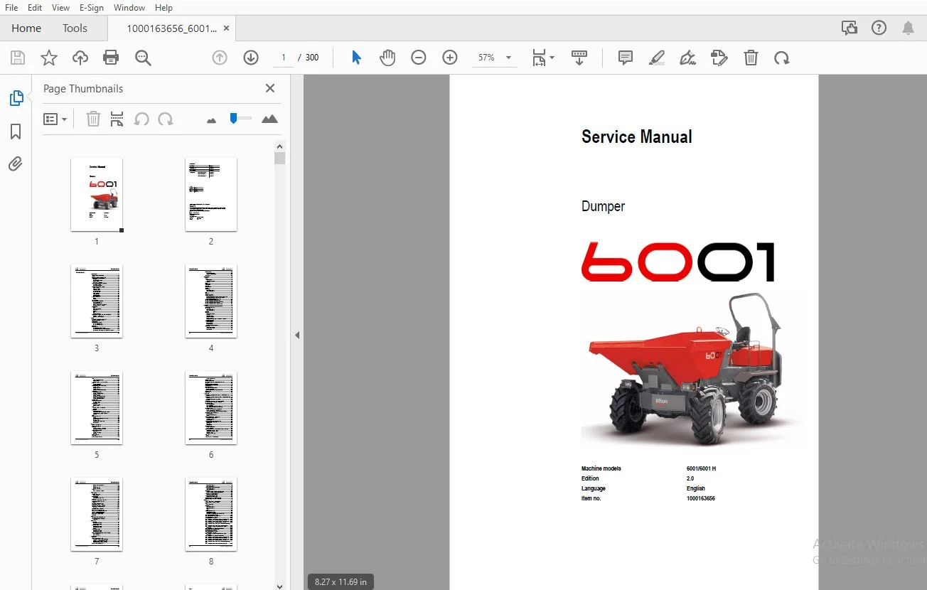
FILE DETAILS:
WACKER NEUSON 6001 DUMPER SERVICE MANUAL 1000163656 – PDF DOWNLOAD
Language : English
Pages : 300
Downloadable : Yes
File Type : PDF
IMAGES PREVIEW OF THE MANUAL:
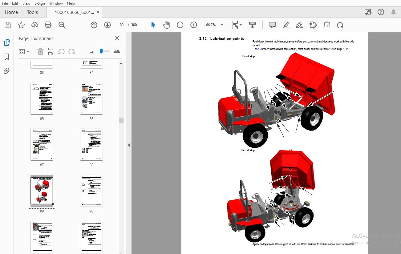
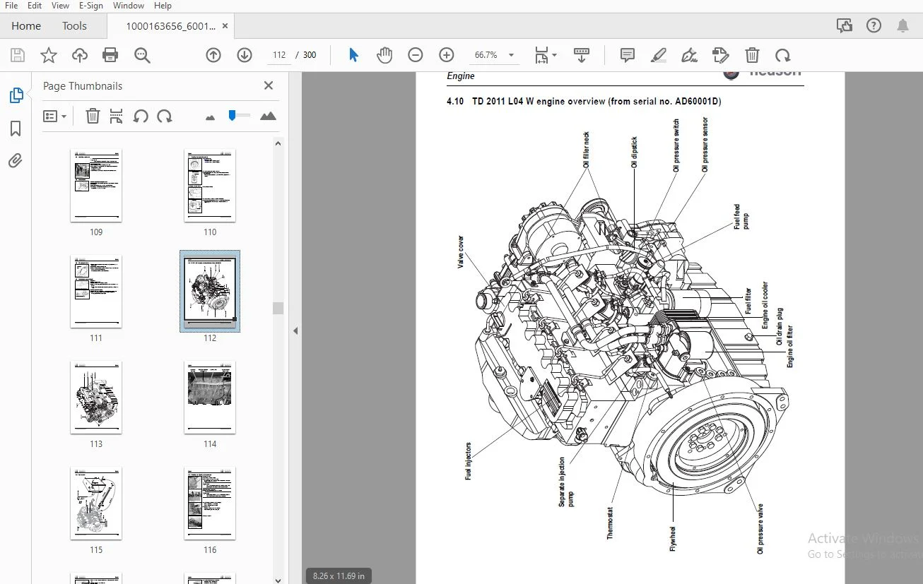
TABLE OF CONTENTS:
WACKER NEUSON 6001 DUMPER SERVICE MANUAL 1000163656 – PDF DOWNLOAD
Service Manual..............................................................................................................  1
	Table of contents.......................................................................................................  3
		Safety Symbols Found in this Manual 0-1.............................................................................  3
		Warranty 0-1........................................................................................................  3
		Designated Use and Exemption from Liability 0-1.....................................................................  3
		General Conduct and Safety Instructions 0-2.........................................................................  3
		Staff Qualifications and Basic Responsibilities 0-3.................................................................  3
		Safety instructions Regarding Operation 0-4.........................................................................  3
		Trailering and Transport 0-6........................................................................................  3
		Temperature Range 0-7...............................................................................................  3
		Safety Guidelines for Maintenance 0-7...............................................................................  3
		Special Hazards 0-9.................................................................................................  3
		Safety Guidelines while using Internal Combustion Engines 0-10......................................................  3
		Important information on this Service Manual 1-1....................................................................  3
		Type labels and component numbers 1-2...............................................................................  3
		Machine overview 1-5................................................................................................  3
		Operating equipment overview 1-7....................................................................................  3
		Control stand 1-9...................................................................................................  3
		Instrument panel 1-12...............................................................................................  3
		Maintenance prop 1-15...............................................................................................  4
		Centre pivot prop 1-16..............................................................................................  4
		Chassis 2-1.........................................................................................................  4
		Engine 2-1..........................................................................................................  4
		Travelling drive 2-2................................................................................................  4
		Brakes 2-2..........................................................................................................  4
		Steering system 2-3.................................................................................................  4
		Work hydraulics 2-3.................................................................................................  4
		Loader unit 2-3.....................................................................................................  4
		Drive specifications 2-3............................................................................................  4
		Vibration 2-3.......................................................................................................  4
		Electric system 2-4.................................................................................................  4
		Tyres 2-6...........................................................................................................  4
		Noise levels 2-6....................................................................................................  4
		Coolant compound table 2-7..........................................................................................  4
		General tightening torques 2-7......................................................................................  4
		Dimensions model 6001 (up to AB60997D) 2-11.........................................................................  4
		Dimensions model 6001 HF (Hydrostat/front tip) 2-12.................................................................  4
		Dimensions model 6001 HF (Hydrostat/front tip) with cab 2-13........................................................  4
		Dimensions model 6001 HS (Hydrostat/swivel) 2-14....................................................................  4
		Dimensions model 6001 HS (Hydrostat/swivel) with cab 2-15...........................................................  4
		Engine/machine fluids and lubricants (up to AB60997D) 3-1...........................................................  4
		Maintenance plan (overview) 3-3.....................................................................................  4
		Service package 3-6.................................................................................................  4
		Introduction 3-6....................................................................................................  4
		Fuel system 3-7.....................................................................................................  4
		Engine lubrication system 3-11......................................................................................  4
		Cooling system 3-15.................................................................................................  4
		Air filter 3-19.....................................................................................................  5
		V-belt 3-21.........................................................................................................  5
		Gearbox lubrication system (up to AB60997D) 3-24....................................................................  5
		Hydraulic system 3-28...............................................................................................  5
		Lubrication points 3-32.............................................................................................  5
		Tyre maintenance and checks 3-33....................................................................................  5
		Changing wheels 3-34................................................................................................  5
		Axles 3-35..........................................................................................................  5
		Electric system 3-36................................................................................................  5
		Battery 3-38........................................................................................................  5
		General maintenance work 3-40.......................................................................................  5
		Engine overview 1104 C-44 4-1.......................................................................................  5
		Engine overview 1104 C-44T 4-3......................................................................................  5
		Fuel system 4-5.....................................................................................................  5
		Checking the injection nozzles 4-8..................................................................................  5
		Adjusting engine revs 4-10..........................................................................................  5
		Compression 4-10....................................................................................................  5
		Checking the coolant thermostat 4-11................................................................................  5
		Oil pressure switch 4-12............................................................................................  6
		Checking the coolant circuit 4-12...................................................................................  6
		TD 2011 L04 W engine overview (from serial no. AD60001D) 4-13.......................................................  6
		Fuel system 4-16....................................................................................................  6
		Checking and adjusting valve clearance 4-17.........................................................................  6
		Checking and adjusting the fuel injectors 4-18......................................................................  6
		Adjusting engine revs 4-20..........................................................................................  6
		Compression pressure 4-21...........................................................................................  6
		Removing/mounting the cylinder head 4-22............................................................................  6
		Replacing the injection pump/setting fuel injection time 4-25.......................................................  6
		Oil pressure switch 4-29............................................................................................  6
		Engine trouble 4-30.................................................................................................  6
		Torque converter gearbox SS620 (from serial no. AA60004D to AB60997D) 5-1...........................................  6
		Torque converter gearbox PS750 (opt) from serial no. AB60078D to AB60997D 5-6.......................................  6
		Cardan shaft 5-11...................................................................................................  6
		Transfer gearbox (from serial no. AA60004D to AB60997D) 5-12........................................................  6
		Travelling drive diagram (up to serial no. AB60997D) 5-14...........................................................  6
		Test instructions SS620 5-15........................................................................................  6
		Test instructions PS750 5-19........................................................................................  6
		Hydrostat (from serial no. AD60001D) 5-22...........................................................................  6
		Variable displacement motor A6VM160HA2U1 5-23.......................................................................  6
		Replacing external components (hydraulic motor) 5-25................................................................  6
		Hydraulic motor settings 5-31.......................................................................................  6
		Variable displacement pump A4VG71DA1D8 (from serial no. AD60001D) 5-33..............................................  6
		Inching valve 5-39..................................................................................................  6
		Replacing components (hydraulic pump) 5-40..........................................................................  6
		Towing 5-46.........................................................................................................  7
		Axle type label 6-1.................................................................................................  7
		Drain, filler and check plug 6-2....................................................................................  7
		Tightening torques 6-4..............................................................................................  7
		Cardan shaft 6-5....................................................................................................  7
		Transfer gearbox (up to serial no. AB60997D) 6-6....................................................................  7
		Semiaxles (up to serial no. AB60997D) 6-8...........................................................................  7
		Wheel hub 6-12......................................................................................................  7
		Brakes (up to serial no. AB60997D) 6-16.............................................................................  7
		Differential (up to serial no. AB60997D) 6-22.......................................................................  7
		Drive housing (from serial no. AD60001D) 6-24.......................................................................  7
		Semiaxles (from serial no. AD60001D) 6-26...........................................................................  7
		Brakes (from serial no. AD60001D) 6-30..............................................................................  7
		Differential (from serial no. AD60001D) 6-32........................................................................  7
		Removing the double cardan shaft (rear axle) 6-33...................................................................  7
		Assembling the joint housing (rear axle) 6-34.......................................................................  7
		Removing the rear axle planetary drive 6-36.........................................................................  7
		Mounting the rear axle planetary drive 6-39.........................................................................  7
		Special tools 6-43..................................................................................................  7
		Brake circuit (up to serial no. AB60997D) 7-1.......................................................................  7
		Brake circuit (from serial no. AD60001D) 7-2........................................................................  7
		Steering circuit 8-1................................................................................................  7
		Steering unit: diagram 8-3..........................................................................................  7
		Steering unit connections 8-4.......................................................................................  7
		Exploded view of steering unit (up to serial no. AB60997D) 8-6......................................................  7
		Gear pump 9-1.......................................................................................................  7
		Manual spool connections: overview 9-2..............................................................................  7
		Dumping the skip: hydraulic diagram 9-6.............................................................................  7
		Swivelling the skip (option): hydraulics diagram 9-8................................................................  8
		Test instructions 9-10..............................................................................................  8
		A4 diagram (up to serial no. AB60997D) 9-12.........................................................................  8
		A4 diagram (from serial no. AD60001D) 9-14..........................................................................  8
		A3 hydraulics diagram (up to serial no. AB60997D) 9-16..............................................................  8
		A3 hydraulics diagram (from serial no. AD60001D) 9-17...............................................................  8
		Ohm's Law (current, voltage, resistance); power 10-1................................................................  8
		Measuring equipment, measuring methods 10-1.........................................................................  8
		Relays 10-2.........................................................................................................  8
		Electric units 10-3.................................................................................................  8
		Operating equipment overview 10-5...................................................................................  8
		Wiring diagram legend (up to AB60997D) 10-9.........................................................................  8
		Wiring diagram version 1 A4 (up to AB60997D) 10-10..................................................................  8
		Wiring diagram legend (from AD60001D) 10-11.........................................................................  8
		A4 wiring diagram (from AD60001D) 10-12.............................................................................  8
		Wiring harness legend 1000129021: main wiring harness (up to AB60997D) 10-13........................................  8
		Wiring harness 1000129021: main wiring harness (up to AB60997D) 10-14...............................................  8
		Wiring harness legend 1000174363: main wiring harness (from AD60001D) 10-15.........................................  8
		Wiring harness 1000182212: main wiring harness (from AD60001D) 10-17................................................  8
		Wiring harness 1000115003 main wiring harness with Powershift option (legend) 10-18.................................  8
		Wiring harness 1000115003 main wiring harness with Powershift option 10-19..........................................  8
		Wiring harness legend 1000115817: additional Powershift electrics 10-20.............................................  8
		Wiring harness 1000115817: additional Powershift electrics 10-21....................................................  8
		A3 wiring diagram legend (up to AB60997D) 10-25.....................................................................  8
		A3 wiring diagram (up to AB60997D) 10-26............................................................................  8
		Wiring diagram legend (from AD60001D) 10-27.........................................................................  8
		A4 wiring diagram (from AD60001D) 10-28.............................................................................  8
		Wiring harness legend 1000115817: additional Powershift electrics 10-29.............................................  8
		Wiring harness 1000115817: additional Powershift electrics 10-30....................................................  8
		Wiring harness legend 1000115003: main wiring harness (up to AB60997D) 10-31........................................  8
		Wiring harness 1000115003: main wiring harness (up to AB60997D) 10-32...............................................  8
		Wiring harness legend 1000182212: main wiring harness (from AD60001D) 10-33.........................................  8
		Wiring harness 1000182212: main wiring harness (from AD60001D) 10-35................................................  8
		Wiring harness 1000115003 main wiring harness with Powershift option (legend) 10-36.................................  8
		Wiring harness 1000115003 main wiring harness (Powershift option) 10-37.............................................  8
		Wiring harness 1000115002 engine wiring harness (legend) 10-38......................................................  9
		Wiring harness 1000115002 engine wiring harness 10-39...............................................................  9
		Wiring harness legend 1000075039/1000115017 telltale/indicator base - ignition lock base 10-40......................  9
		Wiring harness 1000075039 telltale/indicator base 10-41.............................................................  9
		Wiring harness 1000115017 ignition lock base 10-42..................................................................  9
		Wiring harness legend 1000115006: STVO (Austrian road traffic regulations) wiring harness (up to AB60997D) 10-43....  9
		Wiring harness 1000115006: STVO (Austrian road traffic regulations) wiring harness (up to AB60997D) 10-44...........  9
		Wiring harness legend 1000174957: STVO (Austrian road traffic regulations) wiring harness (from AD60001D) 10-45.....  9
		Wiring harness: STVO (Austrian road traffic regulations) wiring harness 1000174957 (from AD60001D) 10-46............  9
		A................................................................................................................... 10
		F................................................................................................................... 10
		I................................................................................................................... 10
		M................................................................................................................... 10
		O................................................................................................................... 10
		R................................................................................................................... 10
		S................................................................................................................... 10
		T................................................................................................................... 10
		W................................................................................................................... 10
	0 Safety Information.................................................................................................... 11
		0.1 Safety Symbols Found in this Manual............................................................................. 11
		0.2 Warranty........................................................................................................ 11
		0.3 Designated Use and Exemption from Liability..................................................................... 11
		0.4 General Conduct and Safety Instructions......................................................................... 12
		0.5 Staff Qualifications and Basic Responsibilities................................................................. 13
		0.6 Safety instructions Regarding Operation......................................................................... 14
		0.7 Trailering and Transport........................................................................................ 16
		0.8 Temperature Range............................................................................................... 17
		0.9 Safety Guidelines for Maintenance............................................................................... 17
		0.10 Special Hazards................................................................................................ 19
		0.11 Safety Guidelines while using Internal Combustion Engines...................................................... 20
	1 Operation............................................................................................................. 24
		1.1 Important information on this Service Manual.................................................................... 24
		1.2 Type labels and component numbers............................................................................... 25
		1.3 Machine overview................................................................................................ 28
		1.4 Operating equipment overview.................................................................................... 30
		1.5 Control stand................................................................................................... 32
		1.6 Instrument panel................................................................................................ 35
		1.7 Maintenance prop................................................................................................ 38
		1.8 Centre pivot prop............................................................................................... 39
	2 Specifications........................................................................................................ 42
		2.1 Chassis......................................................................................................... 42
		2.2 Engine.......................................................................................................... 42
		2.3 Travelling drive................................................................................................ 43
		2.4 Brakes.......................................................................................................... 43
		2.5 Steering system................................................................................................. 44
		2.6 Work hydraulics................................................................................................. 44
		2.7 Loader unit..................................................................................................... 44
		2.8 Drive specifications............................................................................................ 44
		2.9 Vibration....................................................................................................... 44
		2.10 Electric system................................................................................................ 45
		2.11 Tyres.......................................................................................................... 47
		2.12 Noise levels................................................................................................... 47
		2.13 Coolant compound table......................................................................................... 48
		2.14 General tightening torques..................................................................................... 48
		2.15 Dimensions model 6001 (up to AB60997D)......................................................................... 52
		2.16 Dimensions model 6001 HF (Hydrostat/front tip)................................................................. 53
		2.17 Dimensions model 6001 HF (Hydrostat/front tip) with cab........................................................ 54
		2.18 Dimensions model 6001 HS (Hydrostat/swivel).................................................................... 55
		2.19 Dimensions model 6001 HS (Hydrostat/swivel) with cab........................................................... 56
	3 Maintenance........................................................................................................... 58
		3.1 Engine/machine fluids and lubricants (up to AB60997D)........................................................... 58
		3.2 Maintenance plan (overview)..................................................................................... 60
		3.3 Service package................................................................................................. 63
		3.4 Introduction.................................................................................................... 63
		3.5 Fuel system..................................................................................................... 64
		3.6 Engine lubrication system....................................................................................... 68
		3.7 Cooling system.................................................................................................. 72
		3.8 Air filter...................................................................................................... 76
		3.9 V-belt.......................................................................................................... 78
		3.10 Gearbox lubrication system (up to AB60997D).................................................................... 81
		3.11 Hydraulic system............................................................................................... 85
		3.12 Lubrication points............................................................................................. 89
		3.13 Tyre maintenance and checks.................................................................................... 90
		3.14 Changing wheels................................................................................................ 91
		3.15 Axles.......................................................................................................... 92
		3.16 Electric system................................................................................................ 93
		3.17 Battery........................................................................................................ 95
		3.18 General maintenance work....................................................................................... 97
	4 Engine................................................................................................................100
		4.1 Engine overview 1104 C-44.......................................................................................100
		4.2 Engine overview 1104 C-44T......................................................................................102
		4.3 Fuel system.....................................................................................................104
		4.4 Checking the injection nozzles..................................................................................107
		4.5 Adjusting engine revs...........................................................................................109
		4.6 Compression.....................................................................................................109
		4.7 Checking the coolant thermostat.................................................................................110
		4.8 Oil pressure switch.............................................................................................111
		4.9 Checking the coolant circuit....................................................................................111
		4.10 TD 2011 L04 W engine overview (from serial no. AD60001D).......................................................112
		4.11 Fuel system....................................................................................................115
		4.12 Checking and adjusting valve clearance.........................................................................116
		4.13 Checking and adjusting the fuel injectors......................................................................117
		4.14 Adjusting engine revs..........................................................................................119
		4.15 Compression pressure...........................................................................................120
		4.16 Removing/mounting the cylinder head............................................................................121
		4.17 Replacing the injection pump/setting fuel injection time.......................................................124
		4.18 Oil pressure switch............................................................................................128
		4.19 Engine trouble.................................................................................................129
	5 Travelling drive......................................................................................................132
		5.1 Torque converter gearbox SS620 (from serial no. AA60004D to AB60997D)...........................................132
		5.2 Torque converter gearbox PS750 (opt) from serial no. AB60078D to AB60997D.......................................137
		5.3 Cardan shaft....................................................................................................142
		5.4 Transfer gearbox (from serial no. AA60004D to AB60997D).........................................................143
		5.5 Travelling drive diagram (up to serial no. AB60997D)............................................................145
		5.6 Test instructions SS620.........................................................................................146
		5.7 Test instructions PS750.........................................................................................150
		5.8 Hydrostat (from serial no. AD60001D)............................................................................153
		5.9 Variable displacement motor A6VM160HA2U1........................................................................154
		5.10 Replacing external components (hydraulic motor)................................................................156
		5.11 Hydraulic motor settings.......................................................................................162
		5.12 Variable displacement pump A4VG71DA1D8 (from serial no. AD60001D)..............................................164
		5.13 Inching valve..................................................................................................170
		5.14 Replacing components (hydraulic pump)..........................................................................171
		5.15 Towing.........................................................................................................177
	6 Axles.................................................................................................................180
		6.1 Axle type label.................................................................................................180
		6.2 Drain, filler and check plug....................................................................................181
		6.3 Tightening torques..............................................................................................183
		6.4 Cardan shaft....................................................................................................184
		6.5 Transfer gearbox (up to serial no. AB60997D)....................................................................185
		6.6 Semiaxles (up to serial no. AB60997D)...........................................................................187
		6.7 Wheel hub.......................................................................................................191
		6.8 Brakes (up to serial no. AB60997D)..............................................................................195
		6.9 Differential (up to serial no. AB60997D)........................................................................201
		6.10 Drive housing (from serial no. AD60001D).......................................................................203
		6.11 Semiaxles (from serial no. AD60001D)...........................................................................205
		6.12 Brakes (from serial no. AD60001D)..............................................................................209
		6.13 Differential (from serial no. AD60001D)........................................................................211
		6.14 Removing the double cardan shaft (rear axle)...................................................................212
		6.15 Assembling the joint housing (rear axle).......................................................................213
		6.16 Removing the rear axle planetary drive.........................................................................215
		6.17 Mounting the rear axle planetary drive.........................................................................218
		6.18 Special tools..................................................................................................222
	7 Brakes................................................................................................................224
		7.1 Brake circuit (up to serial no. AB60997D).......................................................................224
		7.2 Brake circuit (from serial no. AD60001D)........................................................................225
	8 Steering system.......................................................................................................228
		8.1 Steering circuit................................................................................................228
		8.2 Steering unit: diagram..........................................................................................230
		8.3 Steering unit connections.......................................................................................231
		8.4 Exploded view of steering unit (up to serial no. AB60997D)......................................................233
	9 Hydraulic system......................................................................................................236
		9.1 Gear pump.......................................................................................................236
		9.2 Manual spool connections: overview..............................................................................237
		9.3 Dumping the skip: hydraulic diagram.............................................................................241
		9.4 Swivelling the skip (option): hydraulics diagram................................................................243
		9.5 Test instructions...............................................................................................245
		9.6 A4 diagram (up to serial no. AB60997D)..........................................................................247
		9.7 A4 diagram (from serial no. AD60001D)...........................................................................249
		9.8 A3 hydraulics diagram (up to serial no. AB60997D)...............................................................  0
		9.9 A3 hydraulics diagram (from serial no. AD60001D)................................................................  0
	10 Electric system......................................................................................................254
		10.1 Ohm's Law (current, voltage, resistance); power................................................................254
		10.2 Measuring equipment, measuring methods.........................................................................254
		10.3 Relays.........................................................................................................255
		10.4 Electric units.................................................................................................256
		10.5 Operating equipment overview...................................................................................258
		10.6 Wiring diagram legend (up to AB60997D).........................................................................262
		10.7 Wiring diagram version 1 A4 (up to AB60997D)...................................................................263
		10.8 Wiring diagram legend (from AD60001D)..........................................................................264
		10.9 A4 wiring diagram (from AD60001D)..............................................................................265
		10.10 Wiring harness legend 1000129021: main wiring harness (up to AB60997D)........................................266
		10.11 Wiring harness 1000129021: main wiring harness (up to AB60997D)...............................................267
		10.12 Wiring harness legend 1000174363: main wiring harness (from AD60001D).........................................268
		10.13 Wiring harness 1000182212: main wiring harness (from AD60001D)................................................270
		10.14 Wiring harness 1000115003 main wiring harness with Powershift option (legend).................................271
		10.15 Wiring harness 1000115003 main wiring harness with Powershift option..........................................272
		10.16 Wiring harness legend 1000115817: additional Powershift electrics.............................................273
		10.17 Wiring harness 1000115817: additional Powershift electrics....................................................274
		10.6 A3 wiring diagram legend (up to AB60997D)......................................................................  0
		10.7 A3 wiring diagram (up to AB60997D).............................................................................  0
		10.8 Wiring diagram legend (from AD60001D)..........................................................................  0
		10.9 A4 wiring diagram (from AD60001D)..............................................................................  0
		10.10 Wiring harness legend 1000115817: additional Powershift electrics.............................................  0
		10.11 Wiring harness 1000115817: additional Powershift electrics....................................................  0
		10.12 Wiring harness legend 1000115003: main wiring harness (up to AB60997D)........................................  0
		10.13 Wiring harness 1000115003: main wiring harness (up to AB60997D)...............................................  0
		10.14 Wiring harness legend 1000182212: main wiring harness (from AD60001D).........................................  0
		10.15 Wiring harness 1000182212: main wiring harness (from AD60001D)................................................  0
		10.16 Wiring harness 1000115003 main wiring harness with Powershift option (legend).................................  0
		10.17 Wiring harness 1000115003 main wiring harness (Powershift option).............................................  0
		10.18 Wiring harness 1000115002 engine wiring harness (legend)......................................................  0
		10.19 Wiring harness 1000115002 engine wiring harness...............................................................  0
		10.20 Wiring harness legend 1000075039/1000115017 telltale/indicator base - ignition lock base......................  0
		10.21 Wiring harness 1000075039 telltale/indicator base.............................................................  0
		10.22 Wiring harness 1000115017 ignition lock base..................................................................  0
		10.23 Wiring harness legend 1000115006: STVO (Austrian road traffic regulations) wiring harness (up to AB60997D)....  0
		10.24 Wiring harness 1000115006: STVO (Austrian road traffic regulations) wiring harness (up to AB60997D)...........  0
		10.25 Wiring harness legend 1000174957: STVO (Austrian road traffic regulations) wiring harness (from AD60001D).....  0
		10.26 Wiring harness: STVO (Austrian road traffic regulations) wiring harness 1000174957 (from AD60001D)............  0
DESCRIPTION:
WACKER NEUSON 6001 DUMPER SERVICE MANUAL 1000163656 – PDF DOWNLOAD
This Service Manual contains important information on how to service your machine safely, correctly and economically. Therefore, it aims not only at new operators, but it also serves as a reference for experienced ones. After you will have read this Service Manual, your knowledge will help you avoid danger and reduce repair costs and downtimes. You will thereby increase the reliability and the service life of the machine.
Careful and prudent working is the best way to avoid accidents!
Operational safety and readiness of the machine do not only depend on your skill, but also on maintenance and servicing of the machine.
Insist on using original spare parts when carrying out maintenance and repair work. This ensures operational safety and readiness of the dumper, and maintains its value.
Your Neuson dealer will be pleased to answer any further questions regarding the machine or the Service Manual.
S.S 02/01/2025