Wacker Neuson 6503 Mobile Excavator Service Manual 1000165866 PDF
$28.95
Wacker Neuson 6503 Mobile Excavator Service Manual 1000165866 – PDF DOWNLOAD
Description
Wacker Neuson 6503 Mobile Excavator Service Manual 1000165866 – PDF DOWNLOAD
FILE DETAILS:
Wacker Neuson 6503 Mobile Excavator Service Manual 1000165866 – PDF DOWNLOAD
Language : English
Pages : 385
Downloadable : Yes
File Type : PDF
IMAGES PREVIEW OF THE MANUAL:
TABLE OF CONTENTS:
Wacker Neuson 6503 Mobile Excavator Service Manual 1000165866 – PDF DOWNLOAD
Operation
Important information on this service manual 1-1
Identification of warnings and dangers 1-2
Designated use and exemption from liability 1-3
Type labels and component numbers 1-4
Machine overview 1-6
Cab overview 1-7
Up to serial no AD07227 1-7
From serial no AH00708 1-8
Cab (legend) 1-9
Instrument panel overview 1-10
Up to serial no AD07227 1-10
From serial no AH00708 1-11
Instrument panel (legend) 1-12
Engine compartment overview up to serial no AD07227 1-13
Engine compartment overview from serial no AH00708 1-14
Chassis overview 1-15
Tilting the cab 1-16
Summer/winter operation 1-18
Pedal for auxiliary hydraulics/swivelling and rotating the boom 1-19
Battery master switch 1-19
Specifications
Chassis 2-1
Engine 2-1
Fuel injection pump 2-3
Capacities 2-3
Tightening torques 2-3
Hydraulic system 2-4
Auxiliary hydraulics oil flow* 2-5
Screwable hose burst valve 2-5
Undercarriage and swivel unit 2-5
Stabiliser blade 2-5
Electric system 2-5
Fuse box in instrument panel (up to AD07227) 2-6
Main fuse box with relays under the cab (up to AD07227) 2-6
Relays up to serial no AD07227 2-7
Fuse box in instrument panel (from AH00708) 2-7
Main fuse box with relays from serial no AH00708 2-8
Noise levels 2-8
Vibration 2-8
Coolant compound table 2-8
Tyres 2-9
Model-specific tightening torques 2-9
General tightening torques 2-9
Tightening torques for hydraulic screw connections (dry assembly) 2-9
Tightening torques for high-resistance screw connections 2-11
Dimensions model 6503 2-12
Dimensions model 6503 WD with triple articulation boom (option) 2-13
Lift capacity table 6503 WD 2-15
Lift capacity table 6503 with twin tyres (option) 2-16
Lift capacity table 6503 with triple articulation boom (option) 2-17
Lift capacity table 6503 with twin tyres (option) and triple articulation boom (option)
table of contents
I-2 SERV-HB 6503 EN – Ausgabe 2 0 * 6503s11IVZ fm
table of contents
2-18
Lift capacity table 6503 with long stick (option) 2-19
Lift capacity table 6503 with long stick (option) and twin tyres (option) 2-20
Lift capacity table 6503 with long stick (option) and triple articulation boom (option)
2-21
Lift capacity table 6503 with long stick (option), twin tyres (option) and triple articulation
boom (option) 2-22
Kinematics 2-23
Attachments 2-23
Maintenance
Fluids and lubricants 3-1
Additional oil change and filter replacement (hydraulics) 3-2
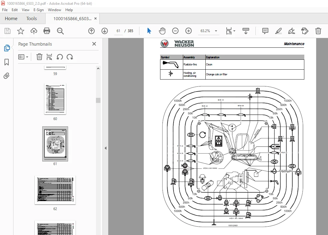
Maintenance label 3-3
Explanation of symbols on the maintenance label 3-3
Maintenance plan (overview) 3-5
Service package 3-9
Up to serial no AD07227 3-9
From serial no AH00708 3-9
Introduction 3-9
Fuel system 3-10
Specific safety instructions 3-10
Refuelling 3-10
Stationary fuel pumps 3-11
Diesel fuel specification 3-11
Bleeding the fuel system 3-11
Emptying the fuel tank 3-12
Fuel prefilter with water separator 3-12
Replacing the fuel filter 3-13
Engine lubrication system 3-14
Checking the oil level 3-14
Filling up engine oil 3-15
Changing engine oil 3-16
Replacing the engine oil filter cartridge 3-17
Cooling system 3-18
Specific safety instructions 3-18
Checking/filling up coolant 3-19
Draining coolant 3-20
Air filter 3-21
Replacing the filter 3-22
Functional check once a week of the dust valve 3-23
V-belt 3-24
Checking V-belt tension 3-24
Retightening the V-belt 3-25
Checking the V-belt of the air conditioning system 3-26
Tightening the V-belt of the air conditioning system 3-26
Pressure check 3-27
General 3-27
Checking pilot control pressure 3-27
Pressure check of variable displacement pump P1 3-28
Pressure check of variable displacement pump P2 3-29
Pressure check of gear pump P3 3-30
Secondary pressure limiting valve of the gear motor 3-31
Measuring ports: overview 3-31
Primary pressure limiting valves 3-31
SERV-HB 6503 EN – Edition 2 0 * 6503s11IVZ fm I-3
table of contents
Test report 3-32
Hydraulic system 3-34
Specific safety instructions 3-34
3-34
Checking the hydraulic oil level 3-35
Filling up hydraulic oil 3-36
Replacing hydraulic oil 3-37
Monitoring the hydraulic oil reflux filter 3-37
Checking hydraulic pressure lines 3-38
Lubrication work 3-39
Stabiliser blade 3-39
Lubrication points on the swivelling console 3-39
Boom lubrication points 3-40
Lubrication points on the stick 3-40
Lubrication strip 3-41
Ring gear 3-41
Maintenance of attachments 3-41
Electric system 3-42
Specific safety instructions 3-42
Service and maintenance work at regular intervals 3-42
Instructions concerning specific components 3-43
Alternator 3-43
Battery 3-44
Jump-starting the engine 3-44
Cab 3-45
Replacing the cab filter 3-45
General maintenance work 3-46
Cleaning 3-46
General instructions for all areas of the machine 3-46
Inside the cab 3-47
Exterior of the machine 3-47
Engine compartment 3-48
Screw connections and attachments 3-48
Pivots and hinges 3-48
Engine
Engine 4TNV98-VNS (American Tier 2 up to serial no AD07227) 4-1
Fuel system 4-3
Removing the valve cover 4-4
Checking and adjusting valve clearance 4-4
Checking valve clearance 4-4
Setting zero play of the valve bridge 4-5
Setting valve clearance 4-5
Tightening order for cylinder head bolts 4-6
Checking the injection nozzles 4-7
Pressure check 4-7
Checking the nozzle jet 4-7
Injection time 4-8
Checking injection time 4-8
Setting injection time 4-9
Replacement of fuel injection pump 4-9
I-4 SERV-HB 6503 EN – Ausgabe 2 0 * 6503s11IVZ fm
table of contents
Adjusting engine revs 4-11
Compression 4-11
Checking the coolant thermostat 4-12
Checking the thermal switch 4-12
Oil pressure switch 4-13
Checking the coolant circuit 4-13
Engine 4TNV98-ZVNS from serial no AH00708 4-14
Fuel system 4-16
Removing the valve cover 4-17
Checking and adjusting valve clearance 4-17
Checking valve clearance 4-17
Setting zero play of the valve bridge 4-18
Setting valve clearance 4-18
Tightening order for cylinder head bolts 4-19
Checking the injection nozzles 4-20
Pressure check 4-20
Checking the nozzle jet 4-20
Injection time 4-21
Checking injection time 4-21
Setting injection time 4-22
Replacement of fuel injection pump 4-23
Compression 4-24
Checking the coolant thermostat 4-24
Checking the thermal switch 4-25
Oil pressure switch 4-25
Checking the coolant circuit 4-25
Engine trouble 4-26
Electronic engine control (E-ECU) 4-28
Features 4-28
Engine error codes 4-29
Error diagnosis 4-33
E-ECU connector assignment 4-33
Important information on the ECU maintenance wiring harness 4-34
Flash code 7 – proportional injection pump solenoid (control rack) 4-35
Related DTC (Diagnostic Trouble Codes) 4-35
Diagnosis description 4-37
Flash code 5 – manual throttle 4-39
Related DTC 4-39
Work description 4-41
Flash code 4-1 ECU internal 4-42
Related DTC 4-42
Work description 4-43
Flash code 4-1 ECU temperature sensor and 2-5 ECU temperature rise alarm
4-44
Related DTC 4-44
Work description 4-45
Flash code 4 coolant temperature sensor and 3-6 coolant temperature rise alarm
4-46
Related DTC 4-46
Work description 4-48
Flash code 2-4 – sensor 5 V 4-50
Related DTC 4-50
Work description 4-51
Flash code 2-3 – power supply voltage 4-53
(1) P0562/1: power supply voltage error (voltage too low) 4-53
DTC detection conditions 4-53
Troubleshooting 4-53
SERV-HB 6503 EN – Edition 2 0 * 6503s11IVZ fm I-5
table of contents
Diagnosis description 4-53
(2) P0563/0: power supply voltage error (voltage too high) 4-54
DTC detection conditions 4-54
Troubleshooting 4-54
Diagnosis description 4-54
Flash code 6 – revs sensor 4-55
Work description 4-57
Flash code 1-1 – backup revs sensor 4-58
Related DTC 4-58
Work description 4-60
Flash code 9 – overspeed error 4-61
(1) P0219/0: overspeed error 4-61
DTC detection conditions 4-61
Troubleshooting 4-61
Diagnosis description 4-61
Flash code 1-7 – proportional solenoid relay of the injection pump (control rack)
4-62
Related DTC 4-62
Work description 4-64
Flash code 1-5 – preheating relay 4-66
Related DTC 4-66
Work description 4-67
Flash code 1-4 – CSD (cold start device) solenoid coil 4-70
Related DTC 4-70
Work description 4-71
Flash code 1-3 – EGR (exhaust gas recirculation) valve 4-73
Related DTC 4-73
Work description 4-75
Flash code 2-1 – oil pressure switch and 3-1 – oil pressure drop error 4-77
Related DTC 4-77
Work description 4-79
Flash code 8 – proportional injection pump solenoid (control rack) 4-81
Related DTC 4-81
Work description 4-83
Flash code 1-6 – main relay 4-85
Related DTC 4-85
Work description 4-87
Flash code 1-2 – CAN (Controller Area Network) communication 4-89
Related DTC 4-89
Work description 4-90
Automatic revs setting 4-91
How it works 4-91
Undercarriage
Hydraulic motor 5-1
Hydraulic motor diagram 5-2
Travelling drive 5-3
Steering axle 5-4
Oil change 5-5
Lubrication 5-5
Checks 5-6
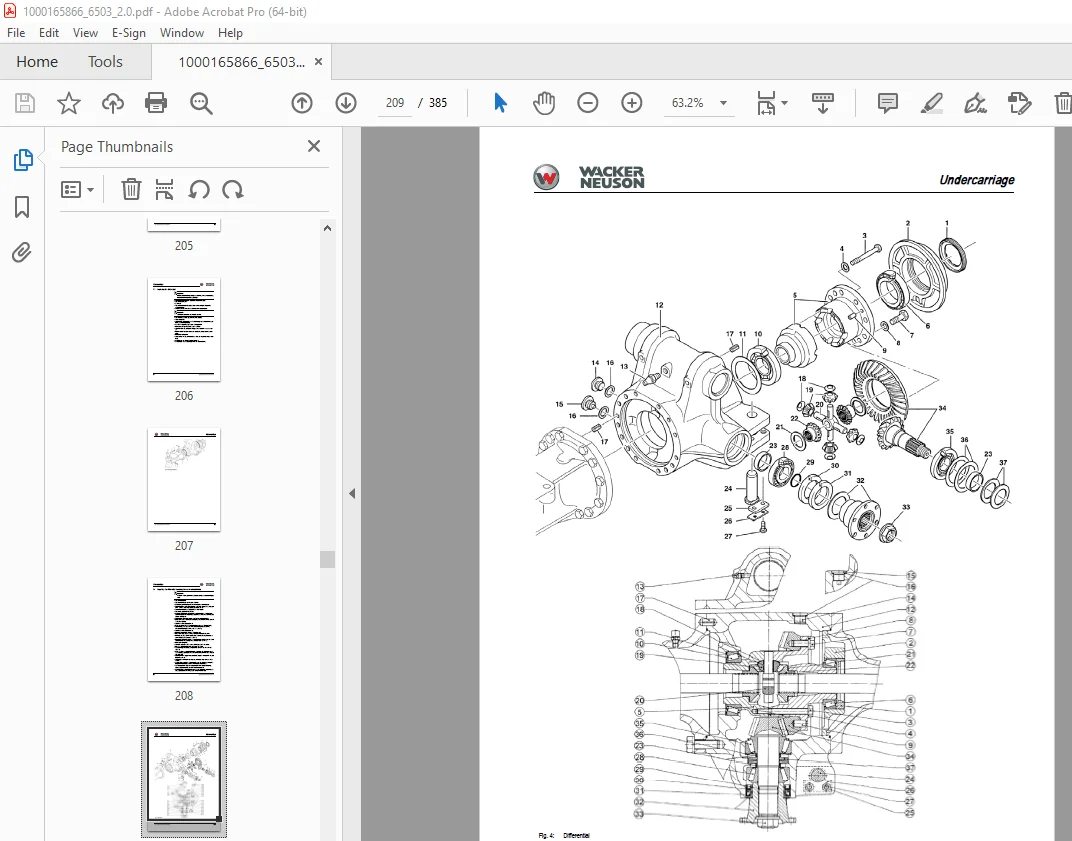
Replacing the differential 5-7
Repairing the differential (replacing the crown wheel/pinion) 5-9
Determining the thickness of the spacer (4/11) 5-11
Spacer 5-11
I-6 SERV-HB 6503 EN – Ausgabe 2 0 * 6503s11IVZ fm
table of contents
Determining the thickness of the spacer (4/36) (setting the contact pattern) 5-12
Adjusting the pinion bearing 5-12
Adjusting the crown wheel bearing 5-12
Checking the contact pattern 5-12
Replacing the differential case 5-14
Planetary cage 5-15
Replacing the complete planetary cage 5-16
Replacing the sun gear shaft 5-16
Replacing the planetary gears 5-16
Replacing planetary pins 5-17
Replacing the ring gear carrier 5-17
Replacing the wheel bearings 5-18
Adjusting the wheel bearings 5-18
Replacing the double cardan shaft 5-19
Replacing the bearing sleeves 5-20
Installing kingpins 5-21
Determining the thickness of the bearing washers 5-22
Replacing the steering ram 5-23
Replacing the track rod 5-23
Adjusting the track 5-24
Friction readjustment 5-24
Replacing brake shoes 5-25
Replacing a complete wheel cylinder 5-26
Rigid planetary axle 5-27
Transfer gearbox Vg1 5-29
Oil change 5-29
Replacing the rotary shaft lip seals on the cardan flange (hydraulic motor side) 5-31
Replacing the rotary shaft lip seals on the cardan flange (brake side) 5-31
Replacing the drive pinion and the bearing 5-32
Replacing the wheel unit and the bearings 5-33
Replacing spur gears and bearings 5-34
Replacing the switch cylinder 5-35
Replacing the gearshift shaft, the shift fork and the sliding sleeve 5-35
Replacing the brake drum 5-36
Replacing brake shoes 5-36
Parking brake/oscillating axle interlock 5-38
Oscillating axle check valve 5-39
Tyres 5-40
Inspection work 5-40
Wheel change 5-40
Hydraulic system
Hydraulic pump PVD-3B-56P-21G5-4626F 6-1
Pump unit: exploded view 6-3
Pilot oil supply unit 6-4
Main valve block with 3rd control circuit and triple articulation boom 6-5
Ports 6-5
Pressure limiting valves 6-6
Pump assignment 6-7
Drive counterbalancing system 6-8
Pump assignment for drive counterbalancing 6-8
Drive counterbalancing diagram 6-9
SERV-HB 6503 EN – Edition 2 0 * 6503s11IVZ fm I-7
table of contents
Regeneration – stick section 6-10
Bucket pre-tension 6-10
Boom raise summation 6-11
Check valve (load retaining valve) 6-12
Flow rate adjustment of auxiliary hydraulics 6-13
Pilot valves 6-14
Joystick 6-14
Joystick legend 6-15
Pilot valve (driving) 6-16
Pilot valve for auxiliary hydraulics 6-17
Steering unit 6-18
Steering system and priority valve 6-20
Valves 6-21
7/2 directional valve (changeover valve) 6-21
Shuttle valve block 6-22
Changeover valve for SAE/ISO controls (option) 6-23
Swivel unit 6-24
Multidisc brake function 6-25
Swivel joint 6-29
Breather filter 6-30
Service brake valve 6-31
Pressure accumulator charge valve 6-32
Troubleshooting in the hydraulic system 6-33
Hydraulics diagram A4 6-34
Hydraulics diagram (legend) 6-35
Hydraulics diagram A3 6-36
Options diagrams 1 from serial no AH00708 6-37
Options diagrams 2 from serial no AH00708 6-38
Electric system
Ohm’s Law (current, voltage, resistance); power 7-1
Measuring equipment, measuring methods 7-1
Cable colour coding 7-3
Relays 7-3
Use, mode of function 7-3
Electric units 7-4
Fuse box on the instrument panel up to serial no AD07227 7-4
Main fuse box with relays up to serial no AD07227 7-4
Relays up to serial no AD07227 7-5
Fuse box on the instrument panel (from serial no AH00708) 7-5
Main fuse box with relays from serial no AH00708 7-6
ECU from serial no AH00708 7-6
Joystick tip switches 7-7
Joystick (left) 7-7
Joystick (right) 7-7
Instrument panel overview 7-8
Switches: overview 7-9
Up to serial no AD07227 7-9
From serial no AH00708 7-9
I-8 SERV-HB 6503 EN – Ausgabe 2 0 * 6503s11IVZ fm
table of contents
Alternator 7-10
Starter 7-10
Wiring diagram up to serial no AD07227 (legend) 7-12
Wiring diagram up to serial no AD07227 7-13
Wiring diagram from serial no AH00708 (legend) 7-14
Wiring diagram 1 from serial no AH00708 7-15
Wiring diagram 2 from serial no AH00708 7-16
Wiring diagram 3 from serial no AH00708 7-17
Wiring diagram for machines with road travel certification (legend) 7-18
Wiring diagram for machines with road travel certification 7-19
Engine wiring harness up to serial no AD07227 (legend) 7-20
Engine wiring harness up to serial no AD07227 7-21
Engine wiring harness from serial no AH00708 (legend) 7-22
Engine wiring harness 1000173970 from serial no AH00708 7-23
Switches wiring harness up to serial no AD07227 (legend) 7-24
Switches wiring harness up to serial no AD07227 7-26
Switches wiring harness 1000173973 from serial no AH00708 (legend) 7-27
Switches wiring harness 1000173973 from serial no AH00708 7-29
Cab wiring harness up to serial no AD07227 (legend) 7-30
Cab wiring harness up to serial no AD07227 7-31
Cab wiring harness 1000174373 from serial no AH00708 (legend) 7-32
Cab wiring harness 1000174373 from serial no AH00708 7-33
Lights wiring harness up to serial no AD07227 (legend) 7-34
Lights wiring harness up to serial no AD07227 7-35
Chassis wiring harness 1000174374 from serial no AH00708 (legend) 7-36
Chassis wiring harness from serial no AH00708 (legend) 7-37
Rear lights wiring harness (legend) 7-38
Rear lights wiring harness 7-39
Wiring diagram up to serial no AD07227 (legend) 7-41
Wiring diagram up to serial no AD07227 7-42
Wiring diagram from serial no AH00708 (legend) 7-43
Wiring diagram 1 from serial no AH00708 7-44
Wiring diagram 2 from serial no AH00708 7-45
Wiring diagram 3 from serial no AH00708 7-46
Wiring diagram for machines with road travel certification A3 (legend) 7-47
Wiring diagram for machines with road travel certification A3 7-48
Engine wiring harness up to serial no AD07227 (legend) 7-49
Engine wiring harness up to serial no AD07227 7-50
Engine wiring harness from serial no AH00708 (legend) 7-51
Engine wiring harness 1000173970 from serial no AH00708 7-52
Switches wiring harness up to serial no AD07227 (legend) 7-53
Switches wiring harness up to serial no AD07227 7-54
Switches wiring harness 1000173973 from serial no AH00708 (legend) 7-55
Switches wiring harness 1000173973 from serial no AH00708 7-56
Cab wiring harness up to serial no AD07227 (legend) 7-57
Cab wiring harness up to serial no AD07227 7-58
Cab wiring harness 1000174373 from serial no AH00708 (legend) 7-59
Cab wiring harness 1000174373 from serial no AH00708 7-60
Lights wiring harness up to serial no AD07227 (legend) 7-61
Lights wiring harness up to serial no AD07227 7-62
Chassis wiring harness 1000174374 from serial no AH00708 (legend) 7-63
Chassis wiring harness from serial no AH00708 (legend) 7-64
Rear lights wiring harness A3 7-65
Options
Air conditioning 8-1
Specific safety instructions 8-1
SERV-HB 6503 EN – Edition 2 0 * 6503s11IVZ fm I-9
table of contents
Specifications 8-1
Installation: overview 8-2
Components 8-3
Filling up the air conditioning system 8-5
Maintenance 8-6
Troubleshooting 8-7
Air-suspension seat 8-9
Connections 8-9
Long stick 8-9
Specifications 8-9
Control circuit (pipework) connections for grab 8-9
3rd control circuit connections 8-10
Auxiliary hydraulics connections 8-10
Quickhitch couplings 8-11
Attachments 8-11
Fuel-filling pump 8-12
Connections up to serial no AD07227 8-13
Central lubrication system 8-14
Position 8-14
Ports 8-14
Function 8-15
Adjusting breaks and lubrication times 8-16
Repair in case of clogging 8-16
Service valve 8-18
Function 8-18
Safe load indicator D (safety valve for boom) 8-19
Position 8-19
Setting the pressure switch 8-19
Function 8-20
Diagram 8-20
Safe load indicator F (safety valves for boom and stick) 8-21
Position 8-21
Setting the pressure switch 8-21
Function 8-22
Diagram 8-22
3rd control circuit 8-24
Function 8-24
Diagram 8-24
Triple articulation boom 8-25
Function 8-25
Diagram 8-25
Proportional controls for auxiliary hydraulics 8-26
Function 8-26
Diagram 8-26
Auxiliary hydraulics shock cartridge 8-27
3rd control circuit shock cartridge 8-28
Drive interlock (antitheft protection) 8-29
Position 8-29
Disabling the drive interlock 8-29
Enabling the drive interlock 8-29
Programming 8-29
Quickhitch 8-31
Proportional controls 8-32
Function 8-32
Ports 8-32
Overview 8-33
Wiring harness 8-34
I-10 SERV-HB 6503 EN – Ausgabe 2 0 * 6503s11IVZ fm
table of contents
Control unit 8-34
Control valve plug assignment 8-35
Safety features 8-36
Measures to be taken in case of malfunctions 8-36
Diagnosis display 8-36
DESCRIPTION:
Wacker Neuson 6503 Mobile Excavator Service Manual 1000165866 – PDF DOWNLOAD
Important information on this service manual:
- This service manual contains important information on how to service your machine safely,
correctly and economically. Therefore, it aims not only at new operators, but it also serves
as a reference for experienced ones. Your knowledge and skills will help to avoid
dangerous situations and reduce repair costs and downtimes. Furthermore, the reliability
and the service life of the machine will be increased by following the instructions in the
service manual. - Careful and prudent working is the best way to avoid accidents.
- Operational safety and readiness of the machine do not only depend on your skill, but also
on maintenance and servicing of the machine. - Insist on using original spare parts when carrying out maintenance and repair work. This
ensures operational safety and readiness of your machine, and maintains its value. - Your Wacker Neuson After-Sales Service will be pleased to answer any further questions
regarding the machine or the service manual.
S.V 31/12/24