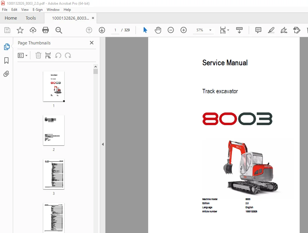
Wacker Neuson 8003 Track Excavator Service Manual 1000132826 PDF
$28.95
Wacker Neuson 8003 Track Excavator Service Manual 1000132826 – PDF DOWNLOAD
Description
Wacker Neuson 8003 Track Excavator Service Manual 1000132826 – PDF DOWNLOAD
FILE DETAILS:
Wacker Neuson 8003 Track Excavator Service Manual 1000132826 – PDF DOWNLOAD
Language : English
Pages : 329
Downloadable : Yes
File Type : PDF
IMAGES PREVIEW OF THE MANUAL:
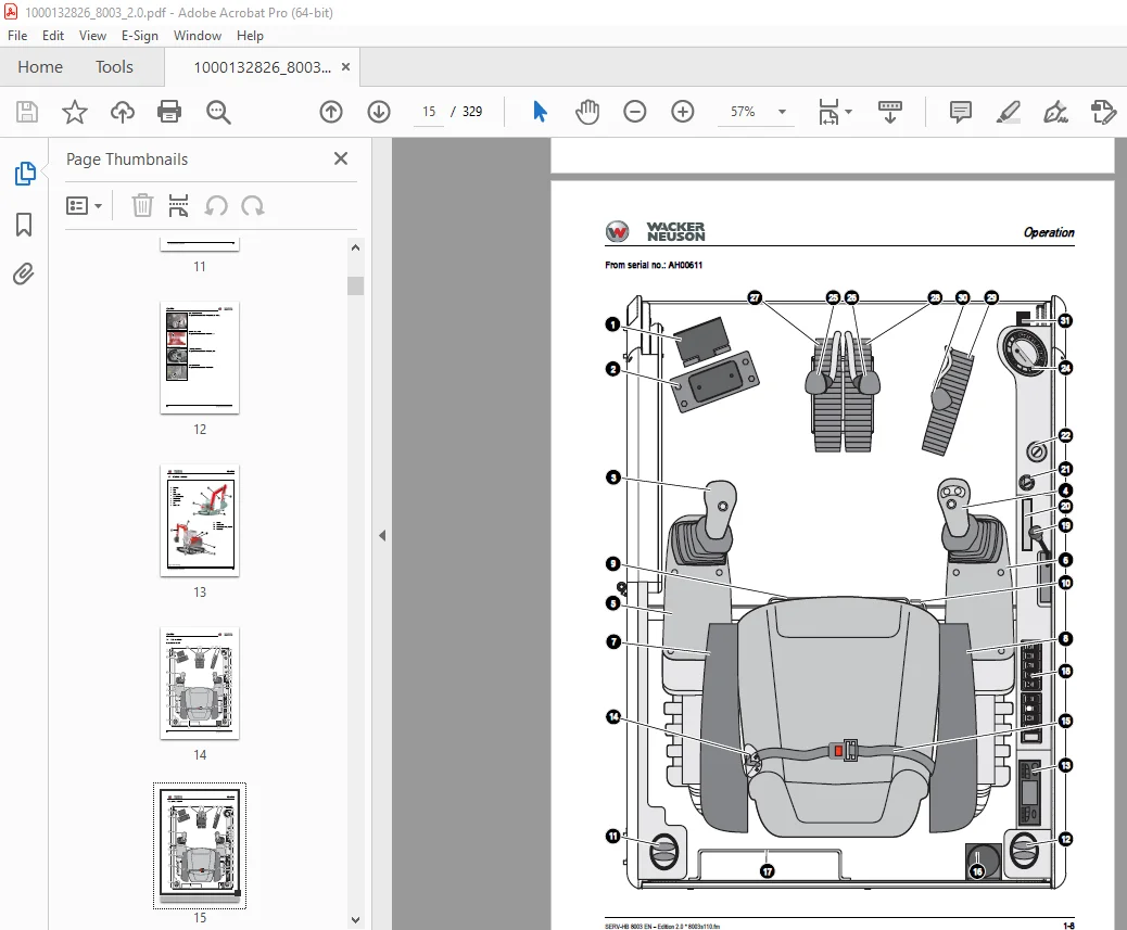
TABLE OF CONTENTS:
Wacker Neuson 8003 Track Excavator Service Manual 1000132826 – PDF DOWNLOAD
Operation
Important information on this service manual 1-1
Abbreviations/symbols 1-1
Identification of warnings and dangers 1-2
Designated use and exemption from liability 1-3
Type labels and component numbers 1-4
Serial number 1-4
Cab number 1-4
Engine number 1-4
Hydraulic pump number 1-5
Control valve number 1-5
Travelling drive number 1-5
Swivel unit number 1-5
Machine overview 1-6
Cab overview 1-7
Cab (legend) 1-9
Instrument panel overview 1-10
Instrument panel (legend) 1-12
Engine compartment up to serial no AD07187 (overview) 1-13
Engine compartment from serial no AH00611 (overview) 1-14
Chassis overview 1-15
Tilting the cab 1-16
Summer/winter operation 1-18
Turning the auxiliary hydraulics/boom swivel pedal around 1-19
Specifications
Chassis 2-1
Engine 2-1
Hydraulic system 2-4
Undercarriage and swivel unit 2-5
Stabiliser blade 2-5
Electric system 2-5
Noise levels 2-7
Vibration 2-7
Coolant compound table 2-8
Model-specific tightening torques 2-8
General tightening torques 2-8
Dimensions model 8003 2-13
Lift capacity table 8003 2-14
Lift capacity table 8003 with long stick 2-15
Lift capacity table 8003 with counterweight 2-16
Lift capacity table 8003 with long stick and counterweight 2-17
Lift capacity table 8003 Vario (option) 2-18
Kinematics 2-19
Maintenance
Fluids and lubricants 3-1
Maintenance label 3-3
Maintenance plan (overview) 3-5
Service package 3-9
Introduction 3-9
Fuel system 3-10
General 3-11
Refuelling from barrels 3-11
Engine lubrication system 3-14
Checking the oil level 3-14
Table of contents
I-2 SERV-HB 8003 EN – Edition 2 0 * 8003s11IVZ fm
Table of contents
Cooling system 3-18
Checking the coolant level 3-19
Filling up coolant 3-20
Air filter 3-21
V-belt 3-24
Pressure check 3-27
Test report 3-32
Hydraulic system 3-35
Travelling drive 3-40
Chains 3-41
Lubrication work 3-43
Electric system 3-46
Cab 3-49
General maintenance work 3-50
When using washing solvents 3-50
When using compressed air 3-50
When using a high-pressure cleaner or steam jet 3-50
When using volatile and easily flammable anticorrosion agents and sprays: 3-50
Cleaning the seat belt: 3-51
Engine
Engine 4TNV98-VNS (up to serial no AD07187 American Tier 2) 4-1
Fuel system 4-3
Removing the valve cover 4-4
Checking and adjusting valve clearance 4-4
Tightening order for cylinder head bolts 4-6
Checking the injection nozzles 4-7
Checking the nozzle jet 4-7
Injection time 4-8
Adjusting engine revs 4-10
Compression 4-10
Checking the coolant thermostat 4-10
Checking the thermal switch 4-11
Oil pressure switch 4-11
Checking the coolant circuit 4-12
Engine 4TNV98-ZVNS from serial no AH00611 4-13
Fuel system 4-15
Removing the valve cover 4-16
Checking and adjusting valve clearance 4-16
Tightening order for cylinder head bolts 4-18
Checking the injection nozzles 4-19
Checking the nozzle jet 4-19
Injection time 4-20
Compression 4-23
Checking the coolant thermostat 4-23
Checking the thermal switch 4-24
Oil pressure switch 4-24
Checking the coolant circuit 4-24
Engine trouble 4-25
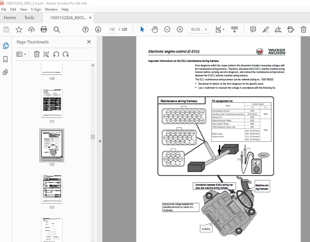
Electronic engine control (E-ECU) 4-27
Engine error codes 4-28
Error diagnosis 4-32
Automatic revs setting 4-90
Automatic revs setting enabled 4-90
Hydraulic system
Hydraulic pump AP2D36LV3RS6-874-P 5-1
Main valve block 5-6
SERV-HB 8003 EN – Edition 2 0 * 8003s11IVZ fm I-3
Table of contents
Drive counterbalancing system 5-13
Boom raise summation 5-15
Boom check valve (load retaining valve) 5-16
Stick ram summation 5-17
Stick check valve (load retaining valve) 5-18
Pilot valves 5-19
Valves 5-25
Pressure cutoff valve 5-27
Travelling drive up to serial no AC 02956 5-32
Auto2Speed drive from serial no AC 02957 5-34
Swivel unit 5-37
Swivel joint 5-43
Breather filter 5-44
Troubleshooting in the hydraulic system 5-45
Hydraulics diagram A4 5-46
Hydraulics diagram (legend) 5-47
Hydraulics diagram 5-48
Options diagram 1 5-49
Options diagram 2 5-50
Main valve block diagram 5-51
Electric system
Ohm’s Law (current, voltage, resistance); power 6-1
Measuring equipment, measuring methods 6-1
Cable colour coding 6-3
Relays 6-3
Electric units 6-4
Fuse box on the instrument panel up to serial no AD07187 6-4
Main fuse box with relays up to serial no AD07187 6-4
Relays up to serial no AD07187 6-5
Fuse box on the instrument panel from serial no AH00611 6-5
Main fuse box with relays from serial no AH00611 6-6
ECU from serial no AH00611 6-7
Socket 6-7
Joystick tip switches 6-8
Instrument panel overview 6-9
Switches: overview 6-10
Alternator 6-11
Starter 6-11
Wiring diagram A4 up to serial no AD07187 (legend) 6-13
Wiring diagram A4 up to serial no AD07187 6-14
Wiring diagram A4 from serial no AH00611 (legend) 6-15
Wiring diagram A4 (1) from serial no AH00611 6-16
Wiring diagram A4 (2) from serial no AH00611 6-17
Engine – chassis A4 wiring harness 1000116497 up to serial no AD07187 (legend)
6-18
Engine – chassis A4 wiring harness 1000116497 up to serial no AD07187 6-19
Engine – chassis A4 wiring harness 1000173970 from serial no AH00611 (legend)
6-20
Engine – chassis A4 wiring harness 1000173970 from serial no AH00611 6-21
Wiring harness 1000125106 switches A4 (legend) 6-22
Wiring harness 1000125106 switches A4 6-23
Wiring harness 1000109629: cab roof 6-24
Wiring harness 1000109628: armrest 6-25
Wiring harness 1000116138: boom working light 6-26
Wiring diagram A3 up to serial no AD07187 (legend) 6-29
Wiring diagram A3 up to serial no AD07187 6-30
I-4 SERV-HB 8003 EN – Edition 2 0 * 8003s11IVZ fm
Table of contents
Wiring diagram A4 from serial no AH00611 (legend) 6-31
Wiring diagram A4 (1) from serial no AH00611 6-32
Wiring diagram A4 (2) from serial no AH00611 6-33
Engine – chassis A3 wiring harness 1000109624 up to serial no AD07187 (legend)
6-34
Engine – chassis A3 wiring harness 1000109624 up to serial no AD07187 6-35
Engine – chassis A3 wiring harness 1000173970 from serial no AH00611 (legend)
6-36
Engine – chassis A3 wiring harness 1000173970 from serial no AH00611 6-37
Wiring harness 1000125106 switches A3 (legend) 6-38
Wiring harness 1000125106 switches A3 6-39
Wiring harness 1000109629: cab roof A3 6-40
Wiring harness 1000109628: armrest A3 6-41
Wiring harness 1000116138: boom working light A3 6-42
Options
Air conditioning 7-1
Air-suspension seat 7-9
Counterweight 7-9
Long stick 7-9
Control circuit (pipework) connections for grab 7-10
3rd control circuit connections 7-10
Auxiliary hydraulics connections 7-11
Neuson Vario 7-13
Fuel-filling pump 7-17
Refuel with the fuel-filling pump 11/A as follows: 7-17
Refuel with the fuel-filling pump 14/A as follows: 7-17
Central lubrication system 7-19
Service valve 7-23
Safe load indicator D (safety valve for boom) 7-24
Safe load indicator F (safety valves for boom and stick) 7-26
3rd control circuit 7-29
Triple articulation boom 7-30
Electric auxiliary hydraulics 7-31
Auxiliary hydraulics shock cartridge 7-32
3rd control circuit shock cartridge 7-33
Drive interlock (antitheft protection) 7-34
Quickhitch 7-36
Proportional controls 7-37
DESCRIPTION:
Wacker Neuson 8003 Track Excavator Service Manual 1000132826 – PDF DOWNLOAD
Important information on this service manual:
This service manual contains important information on how to service your machine safely,
correctly and economically. Therefore, it aims not only at new operators, but it also serves
as a reference for experienced ones. Your knowledge and skills will help to avoid
dangerous situations and reduce repair costs and downtimes. Furthermore, the reliability
and the service life of the machine will be increased by following the instructions in the
service manual.
Careful and prudent working is the best way to avoid accidents!
Operational safety and readiness of the machine do not only depend on your skill, but also
on maintenance and servicing of the machine.
Insist on using original spare parts when carrying out maintenance and repair work. This
ensures operational safety and readiness of your machine, and maintains its value.
Your Wacker Neuson After-Sales Service will be pleased to answer any further questions
regarding the machine or the service manual.
S.V 31/12/24