Wacker Neuson 803/803 Dual Power Track Excavators Service manual – PDF DOWNLOAD
Original price was: $78.00.$24.95Current price is: $24.95.
Wacker Neuson 803/803 Dual Power Track Excavators Service manual – PDF DOWNLOAD
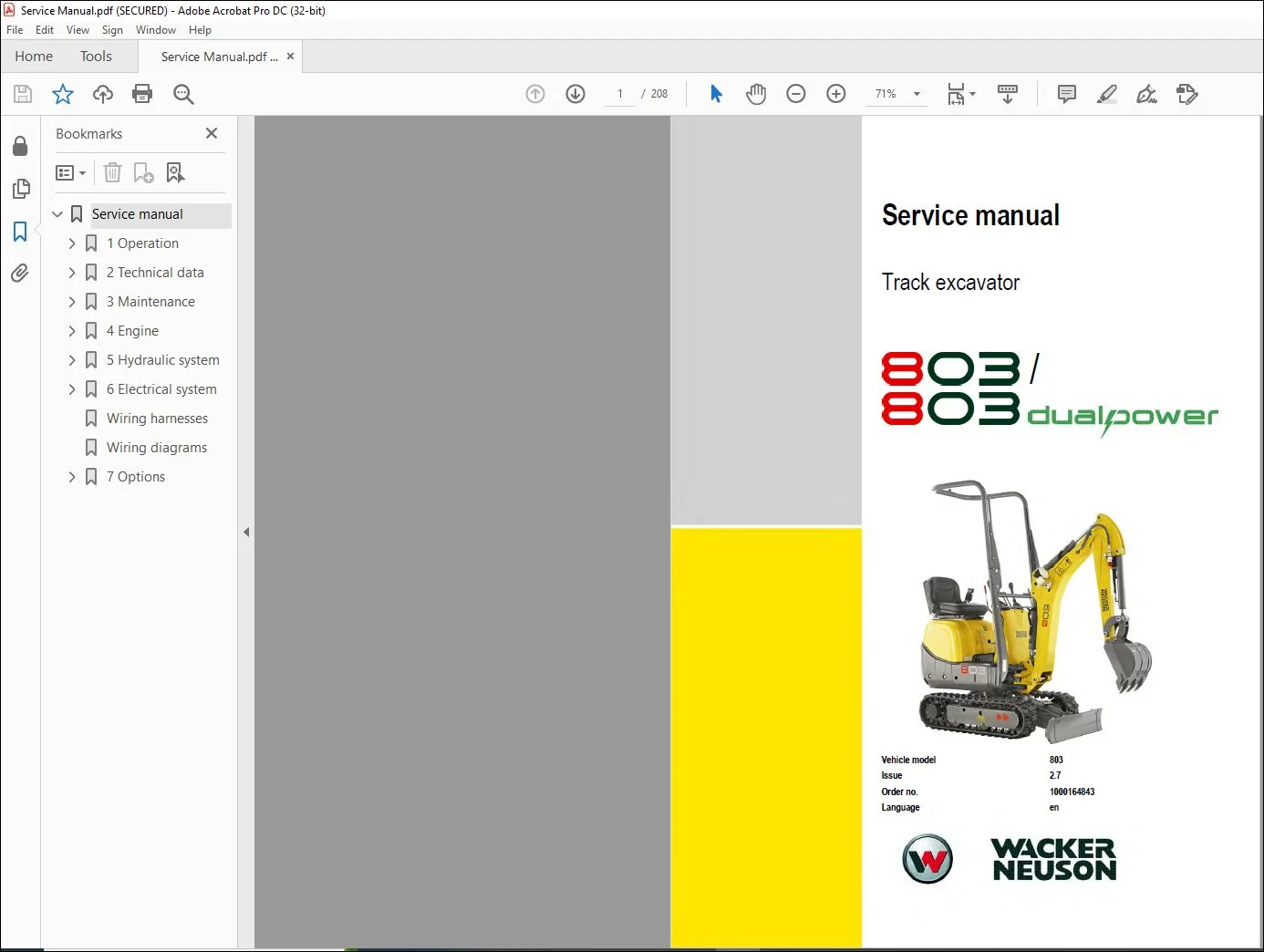
Vehicle model 803
Issue 2.7
Order no. 1000164843
Language en
Description
Wacker Neuson 803/803 Dual Power Track Excavators Service manual – PDF DOWNLOAD
IMAGES PREVIEW OF THE MANUAL:
DESCRIPTION:
Wacker Neuson 803/803 Dual Power Track Excavators Service manual – PDF DOWNLOAD
1 Operation
1.1 Notices on this service manual
- This service manual contains important information on how to service your machine safely, correctly and economically. Therefore, it aims not only at new operators, but it also serves as a reference for experienced ones. It helps to avoid hazardous situations and reduce repair costs and downtimes.
- Furthermore, the reliability and the service life of the vehicle will be increased by following the instructions in the service manual. Careful and prudent working is the best way to avoid accidents! Operational safety and readiness of the vehicle do not only depend on the operator’s skill, but also on maintenance and servicing of the vehicle. For this reason, regular
- maintenance and service work is crucial. Use only original spare parts for repairs. This ensures operational safety and readiness of your machine, and maintains its value. Subject to modifications and printing errors. Your Wacker Neuson technical support will be happy to answer any further questions regarding the machine or the service manual.
TABLE OF CONTENTS:
Wacker Neuson 803/803 Dual Power Track Excavators Service manual – PDF DOWNLOAD
Operation
Notes about the service manual 1-2
Labeling of warnings and dangers 1-3
Explanation of symbols and abbreviation 1-3
Abbreviations 1-4
Conversion table 1-5
Warranty and liability 1-6
Exemption from warranty and liability 1-6
Signage 1-7
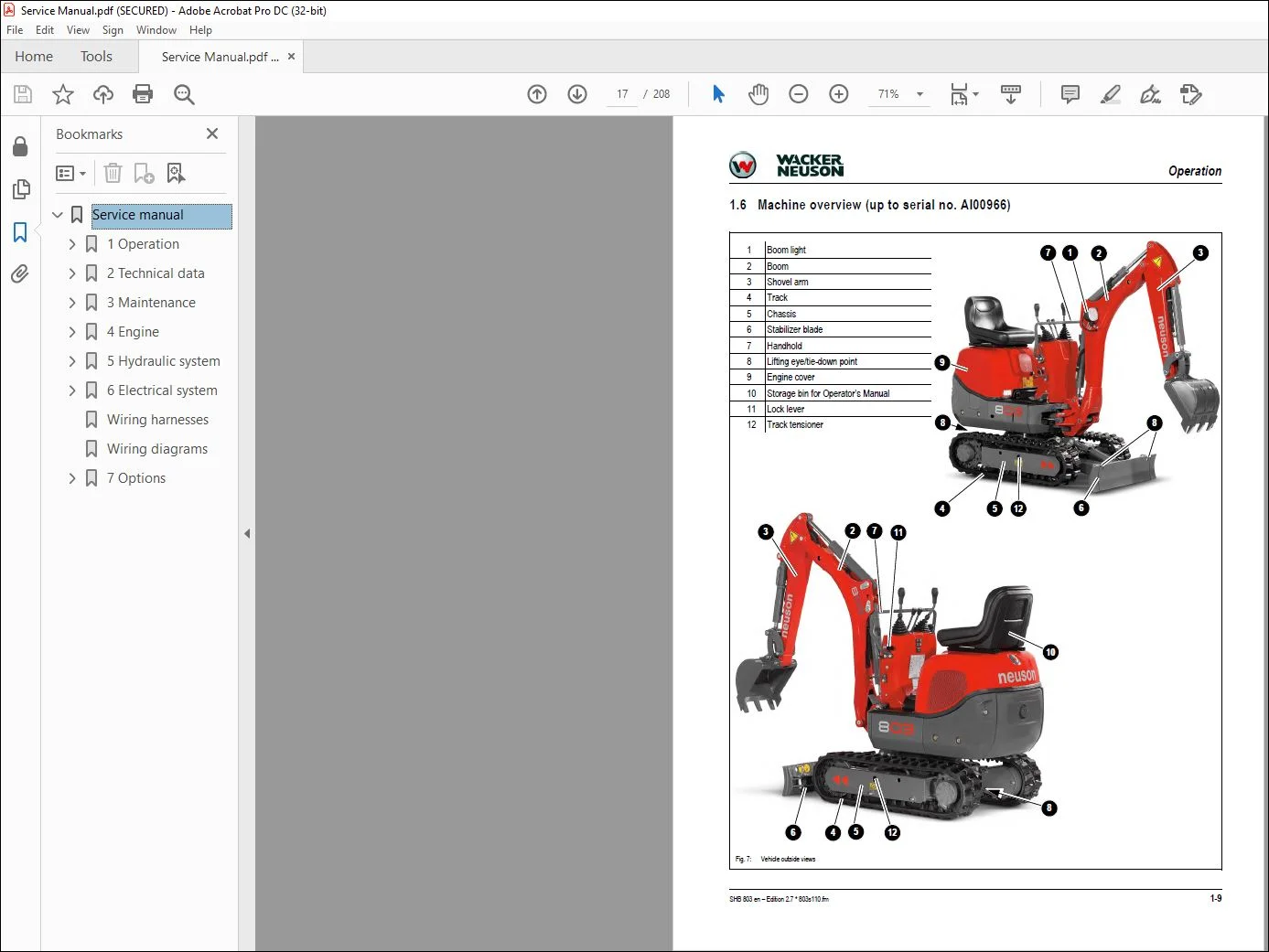
Vehicle overview (up to serial number AI00966) 1-9
Vehicle overview (from serial number AI00967) 1-10
Overview of the control stand (up to serial number AI00814) 1-11
Overview of the control stand (from serial number AI00815) 1-13
Overview of the display elements 1-14
Overview of the engine compartment (up to serial number AI00814) 1-15
Overview of the engine compartment (from serial number AI00815) 1-16
Battery isolator switch 1-17
Technical data
Bulkhead 2-2
Engine 2-2
Injection pump 2-4
Engine capacities 2-4
Engine torque settings 2-4
Hydraulic system 2-4
Auxiliary hydraulics discharge volumes 2-5
Travel gear and turn motor 2-5
Dozer blade 2-5
Screwable hose rupture safeguard valve 2-5
Electrics 2-6
Fuses behind the right side cover 2-6
Relay behind the right side cover 2-7
Fuses and relay for the Dual Power option 2-7
Noise measurement 2-8
Vibration 2-8
Coolant compound table 2-8
Hose identification code 2-8
Model-specific torque settings 2-9
General torque settings 2-9
Torque settings for hydraulic hardware for dry assembly 2-9
Tightening torque settings for high tensile strength screw connections 2-12
Dimensions of model 803 (up to serial number AI00966) 2-13
Dimensions of model 803 with ROPS rollbar (Roll Over Protective Structure) (from serial
number AI00967) 2-14
Dimensions of model 803 without ROPS rollbar (Roll Over Protective Structure) (from
serial number AI00967) 2-15
Lift capacity table 803 RD 2-16
Kinematics 2-16
Maintenance
Notes about maintenance 3-2
Responsibilities and previous conditions 3-2
Important safety instructions about care and maintenance jobs 3-2
Special tool 3-2
Engine/vehicle fluids and lubricants 3-3
Additional oil change and filter replacement of the hydraulics 3-4
Table of Contents
I-2 SHB 803 en – Edition 27 * 803s20IVZfm
Table of Contents
Important notes about operation with bio-hydraulic oil 3-5
Maintenance label 3-6
Explanation of symbols on the maintenance label 3-6
Explanation of labels (up to serial number AF02412) 3-7
Explanation of labels (from serial number AF02413) 3-8
Maintenance schedule (complete overview) 3-9
Fuel system 3-13
Special safety instructions 3-13
Refueling 3-13
Stationary fuel pumps 3-14
Specification of the diesel fuel 3-14
Bleed the fuel system 3-15
Fuel pre-filter with water trap 3-15
Change the fuel filter 3-17
Engine lubrication system 3-18
Check the oil level 3-18
Top off the motor oil 3-19
Change the motor oil 3-20
Replace the motor oil filter element 3-21
Cooling system 3-22
Special safety instructions 3-22
Checking the coolant level/topping off the coolant 3-23
Replace the coolant 3-25
Air cleaner (up to serial number AI00875) 3-26
Replacing air filer element 3-27
Air cleaner (from serial number AI00876) 3-27
Replacing air filer element 3-28
V-belt 3-30
Check the V-belt tension 3-30
Re-tension the V-belt 3-31
Pressure check 3-32
General 3-32
Pressure check of the gear pump P2 3-32
Pressure check of the gear pump P1 3-33
Test log 3-34
Hydraulic system 3-36
Special safety instructions 3-36
Check the hydraulic oil level 3-37
Top off the hydraulic oil 3-38
Change the hydraulic oil 3-39
Replace the filter element 3-39
Check the hydraulic system and hydraulic hoses 3-40
Chains 3-41
Check the track tension 3-41
Setting the chains 3-42
Lubrication points on the levelling jack (up to serial number AI00966) 3-43
Lubrication strip 3-44
Lubrication point overview (from serial number AI00967) 3-45
Park the vehicle 3-46
Lubrication points of the dozer blade and dozer blade cylinder 3-46
Lubrication points of the swiveling cylinder 3-47
Lubrication points of the swiveling cylinder 3-47
Lubrication points of the live ring bearing track 3-48
Lubrication points of the live ring teeth 3-49
Ball sockets (Option ISO/SAE switch-over) 3-50
Maintenance of attachments 3-50
Electrical system 3-51
SHB 803 en – Edition 27 * 803s20IVZfm I-3
Table of Contents
Special safety instructions 3-51
Regular maintenance and service work 3-51
Notes about special elements 3-52
Three-phase current generator 3-52
Battery 3-53
Check the battery degasification hose 3-54
General care and maintenance work 3-55
Cleaning 3-55
General notes for all vehicle areas 3-55
Control stand 3-55
Entire vehicle exterior 3-56
Engine compartment 3-56
Screw connections and fastenings 3-56
Pivot points and hinges 3-56
Preparing for immobilization 3-57
Maintenance during long periods of immobilization 3-57
Commissioning after immobilization period 3-57
Engine
Overview of engine 3TNV70-VNS (TIER IV final to 2012) 4-2
Fuel system 4-3
Tapped clearance: Check and set 4-5
Tightening order of the cylinder head 4-6
Check the injection nozzles 4-7
Pressure check 4-7
Injection spray control 4-7
Injection time 4-8
Checking and setting the injection time 4-8
Replacing the injection pump 4-9
Setting the RPMs 4-10
Compression 4-10
Check the coolant thermostat 4-10
Check the thermal overload protection breaker 4-11
Oil pressure switch 4-11
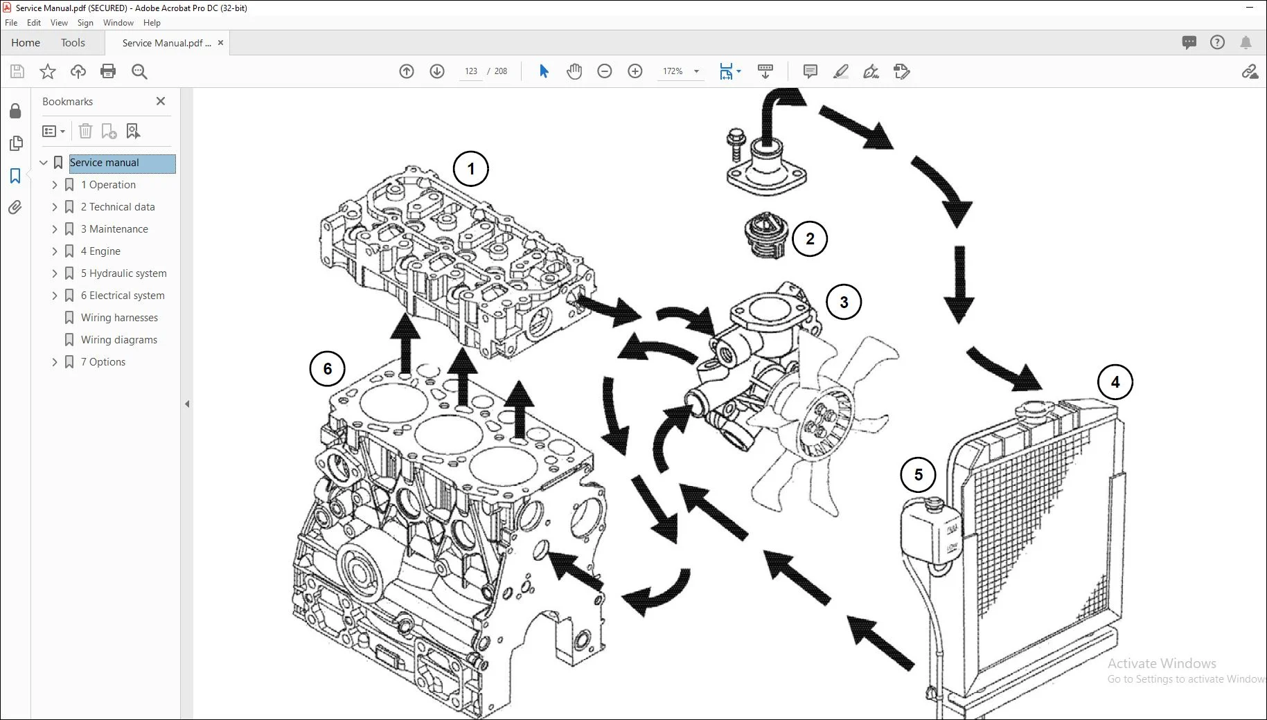
Check the coolant circuit 4-12
Engine faults 4-13
Engine overview 3TNV74F-SNNS (TIER IV final from 2012) 4-15
Fuel system 4-17
Cooling system 4-18
Altitude-dependent power reduction 4-19
Tapped clearance: Check and set 4-20
Tightening order of the cylinder head 4-22
Sequence of disassembling the cheese head screws: 4-22
Sequence of assembling the cheese head screws: 4-22
Check the injection nozzles 4-23
Pressure check 4-23
Injection spray control 4-24
Injection time 4-24
Check the time of injection 4-24
Setting the time of injection 4-26
Disassembling and assembling the injection pump 4-27
Removing the injection pump 4-27
I-4 SHB 803 en – Edition 27 * 803s20IVZfm
Table of Contents
Installing the injection pump 4-28
Measuring and setting the RPM 4-30
Compression 4-30
Check the coolant thermostat 4-31
Checking the temperature sensor 4-31
Oil pressure switch 4-32
Check the coolant circuit 4-32
Cleaning the coolant channels 4-32
Coolant and fuel hoses 4-33
Crankcase aeration 4-33
Renewing the glow plugs 4-33
Engine faults 4-34
Hydraulics system
Gear pump PGP505B0050CA1H2NJ7J5C-505A00 (TIER IV final up to 2012) 5-2
Pump unit structure 5-3
Gear pump PGP505B0040CA1H2NJ7J5C-505A0040XB1J5B1B1 (TIER IV final from
2012) 5-4
Pump unit structure 5-5
Mobile valve block 5-6
Connections 5-6
Legend 5-7
Mobile valve block detailed plan 5 – 8
Pressure limits 5-9
Pump assignment 5-10
Drive 5-11
Function 5-12
Swivel unit 5-14
Swivel unit 5-15
Swivel implementation 5-16
Gaskets 5-16
Mechanical control 5-17
Joystick (up to serial number AI00814) 5-17
Forward + reverse travel lever (up to serial number AI00814) 5-18
Joystick (from serial number AI00815) 5-19
Forward + reverse travel lever (from serial number AI00815) 5-20
Safety lock lever (from serial number AI00815) 5-21
Hydraulic faults 5-22
Plastic trims 5-22
Legend of the hydraulic diagram 5-24
Hydraulic diagram 5-25
(Dual Power option) hydraulic diagram 5-26
Hydraulics diagram (Dual Power option) from serial no WNCE0801LPAL02441 5-27
Mobile valve block detailed plan 5 – 28
Electrical system
Ohmic law (current, voltage, resistance); Output 6-2
Measuring devices, measuring methods 6-2
Color coding of the lines 6-3
6-3
Relay 6-3
Application, mode of function 6-3
Electrical system 6-4
Fuses behind the right side cover 6-4
Relay behind the right side cover 6-5
SHB 803 en – Edition 27 * 803s20IVZfm I-5
Table of Contents
Fuses and relay for the Dual Power option 6-5
Joystick touch button 6-6
Work lighting 6-6
Dynamo 6-7
Voltage regulator 6-7
Starter 6-7
Legend of the engine wiring harness (TIER IV final to 2012) 6-9
Engine wiring harness (TIER IV final to 2012) 6-9
Legend of the engine wiring harness (TIER IV final from 2012) 6-11
Engine wiring harness (TIER IV final from 2012) 6-11
Wiring harness displays (up to serial number WNCE0801TPAL00923) 6-13
Wiring harness displays (from serial number WNCE0801PPAL00924) 6-14
Cable supply for the operating hour meter 6-15
Wiring harness drive signal (option) 6-16
Wiring harness for horn 6-17
Battery cables 6-18
Wiring harness display (Dual Power option) 6-19
Legend engine/chassis wiring harness (Dual Power option) 6-20
Engine/chassis wiring harness (Dual Power option) 6-21
Seat console wiring harness 6-22
Wiring diagram 6-24
Wiring diagram Tier IV (Yanmar) 6-25
Wiring diagram (Dual Power option) up to serial number WNCE0801LPAL02441 6-26
Wiring diagram (Dual Power option) from serial no WNCE0801LPAL02441 6-27
Options
ROPS (Roll Over Protective Structure) 7-2
TOPS ROPS (Roll Over Protective Structure) – up to serial number AF01416 7-2
Fold-down ROPS (Roll Over Protective Structure) – from serial number AF01417 to
serial number AI00966 7-3
Fold ROPS (Roll Over Protective Structure): 7-3
Tilt ROPS (Roll Over Protective Structure): 7-4
Fold-down (Roll Over Protective Structure) – from serial number AI00967 7-4
Fold ROPS (Roll Over Protective Structure): 7-5
ISO/SAE switch-over (option) 7-6
Driving signal (option) 7-7
Telematics 7-8
Connections 7-8
Functional check/luminous diode 7-8
Zero emission Dual Power drive system 7-9
Overview
Customer Support: [email protected]
PLEASE NOTE:
- This is the same manual used by the DEALERSHIPS to SERVICE your vehicle.
- The manual can be all yours – Once payment is complete, you will be taken to the download page from where you can download the manual. All in 2-5 minutes time!!
- Need any other service / repair / parts manual, please feel free to contact us at heydownloadss @gmail.com . We may surprise you with a nice offer
S.M