Wacker Neuson 9503 Mobile Excavator Operator’s Manual 1000171927 PDF
$28.95
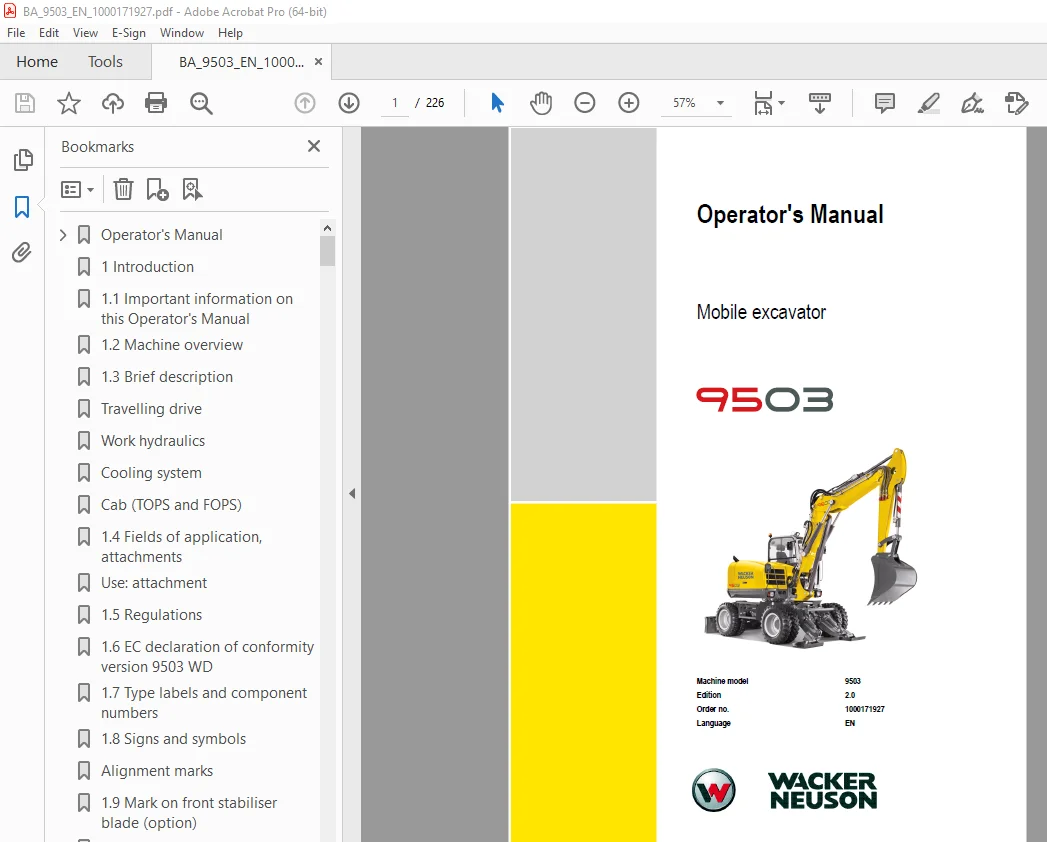
Wacker Neuson 9503 Mobile Excavator Operator’s Manual 1000171927 – PDF DOWNLOAD
Description
Wacker Neuson 9503 Mobile Excavator Operator’s Manual 1000171927 – PDF DOWNLOAD
FILE DETAILS:
Wacker Neuson 9503 Mobile Excavator Operator’s Manual 1000171927 – PDF DOWNLOAD
Language : English
Pages : 226
Downloadable : Yes
File Type : PDF
IMAGES PREVIEW OF THE MANUAL:
DESCRIPTION:
Wacker Neuson 9503 Mobile Excavator Operator’s Manual 1000171927 – PDF DOWNLOAD
Introduction:
1.1 Important information on this Operator’s Manual:
- Please store the Operator’s Manual in the storage bin behind the seat.
- This Operator’s Manual contains important information on how to work safely, correctly
and economically with the machine. Therefore, it aims not only at new operators, but it also
serves as a reference for experienced ones. It helps to avoid dangerous situations and
reduce repair costs and downtimes. Furthermore, the reliability and the service life of the
machine will be increased by following the instructions in the Operator’s Manual. This is
why the Operator’s Manual must always be kept at hand in the machine. - Your own safety, as well as the safety of others, depends to a great extent on how the
machine is moved and operated. Therefore, carefully read and understand this Operator’s
Manual prior to the first drive. This Operator’s Manual will help to familiarise yourself more
easily with the machine, thereby enabling you to use it more safely and efficiently. - Prior to the first drive, carefully read chapter “Safety Instructions” as well, in order to be
prepared for possible dangerous situations, as it will be too late for it during operation. As a
rule, keep the following in mind:
Careful and prudent working is the best way to avoid accidents!
Operational safety and readiness of the machine do not only depend on your skill, but also
on maintenance and servicing of the machine. This is why regular maintenance and service
work is absolutely necessary. Extensive maintenance and repair work must always be
carried out by an expert with appropriate training. Insist on using original spare parts when
carrying out maintenance and repair work. This ensures operational safety and readiness
of your machine, and maintains its value.
• Special equipment and superstructures are not described in this Operator’s Manual.
• We reserve the right to improve the technical standard of our machines without
adapting the Operator’s Manual.
• Modifying Wacker Neuson products and fitting them with additional equipment and
attachments not included in our delivery program requires Wacker Neuson’s written
authorisation, otherwise warranty and product liability for possible damage caused by
these modifications shall not be applicable.
• Subject to modifications and printing errors.
Your Wacker Neuson dealer will be pleased to answer any further questions regarding the
machine or the Operator’s Manual.
TABLE OF CONTENTS:
Wacker Neuson 9503 Mobile Excavator Operator’s Manual 1000171927 – PDF DOWNLOAD
Operator’s Manual 1
Table of contents 3
Important information on this Operator’s Manual 1-1 3
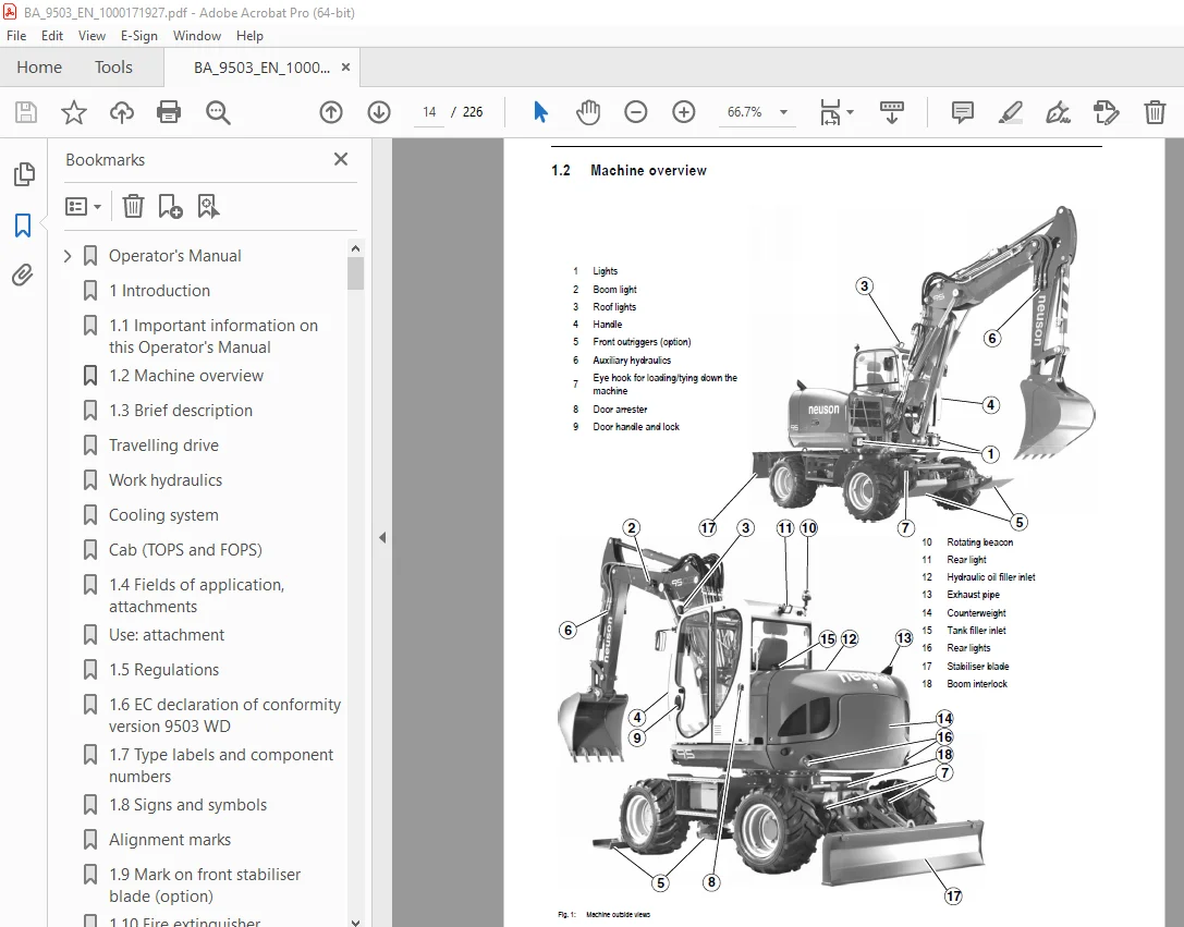
Machine overview 1-2 3
Brief description 1-3 3
Fields of application, attachments 1-5 3
Regulations 1-6 3
EC declaration of conformity version 9503 WD 1-7 3
Type labels and component numbers 1-8 3
Signs and symbols 1-11 3
Mark on front stabiliser blade (option) 1-14 3
Fire extinguisher 1-15 3
Identification of warnings and dangers 2-1 3
Warranty 2-1 3
Designated use and exemption from liability 2-2 3
General conduct and safety instructions 2-3 3
Safety instructions regarding operation 2-5 3
Safety instructions for maintenance 2-10 3
Warning of special hazards 2-12 3
Cab overview 3-2 3
Instrument panel, multifunctional lever, switch consoles: overview 3-4 3
Putting into operation 3-5 3
Telltales and warning lights: overview 3-8 3
Before starting the engine 3-11 3
Starting with the drive interlock (option) 3-13 4
Starting at low temperatures 3-14 4
Engine warm-up 3-14 4
Jump-starting the engine (supply battery) 3-15 4
Hydraulic brake 3-16 4
Service brake 3-16 4
Release lever 3-17 4
Parking brake 3-18 4
Special instructions for driving on public roads 3-19 4
Safety-critical function: work position/road travel 3-20 4
Moving off hydraulically in work position 3-21 4
Changing over to road travel 3-23 4
Moving off on roads 3-23 4
Steering modes 3-25 4
Changing the steering mode (option) 3-26 4
Steering direction changeover 3-27 4
Adjusting the steering column 3-28 4
2nd speed 3-29 4
Locking the oscillating axle 3-30 4
Driving on slopes 3-31 4
Front outriggers (option) 3-33 4
Rear outriggers 3-34 4
Stabiliser blade (option) 3-35 4
Parking the machine 3-36 4
Control elements 3-37 4
Seat adjustment 3-44 5
Seat belt 3-46 5
Emergency exit 3-47 5
Front window 3-48 5
Door 3-49 5
Engine cover 3-51 5
Battery master switch (model 9503) 3-52 5
Cab 3-53 5
Interlocks 3-56 5
Wheel chocks 3-58 5
Towing the mobile excavator 3-59 5
Loading the machine 3-63 5
Working with the machine 3-67 5
Control levers/ISO controls: overview 3-68 5
Changeover valve for SAE/ISO controls (option) 3-71 5
Control lever with proportional controls (option): overview 3-73 5
Control lever if equipped with 3rd control circuit (option): overview 3-76 6
Releasing the pressure on the work hydraulics 3-77 6
Re-equipping attachments 3-78 6
Quickhitch (option) 3-79 6
Hydraulic quickhitch (option) 3-80 6
Powertilt (option) 3-83 6
Auxiliary hydraulics connections 3-88 6
“Hose burst valve” safety feature (option) 3-90 6
Before starting work 3-91 6
Working with the excavator 3-92 6
Grading 3-97 6
Safe load indicator (option) 3-98 6
Applications with lifting gear 3-99 6
Troubleshooting 4-2 6
Malfunctions of the Powertilt unit 4-4 6
Introduction 5-1 6
Fuel system 5-2 6
Engine lubrication system 5-7 7
Engine and hydraulics cooling system 5-9 7
Air filter 5-13 7
V-belts 5-15 7
Hydraulic system 5-18 7
Pilot valve 5-22 7
Overview of lubrication points 5-25 7
Axle mounting 5-30 7
Stop plate fastening of the oscillating axle 5-30 7
Tyres 5-31 7
Travelling drive 5-33 7
Cardan shaft 5-34 7
Central lubrication system (option) 5-35 7
Electrical system 5-38 7
General maintenance work 5-42 8
Maintenance if the machine is out of service for a longer period of time 5-45 8
Fluids and lubricants 5-46 8
Maintenance plan (overview) 5-50 8
Maintenance label 5-54 8
Chassis 6-1 8
Engine 6-1 8
Undercarriage 6-1 8
Brakes 6-2 8
Swivel unit 6-2 8
Steering system 6-3 8
Hydraulics 6-4 8
Electrical system 6-5 8
Noise levels 6-7 8
Outriggers or stabiliser blade (option) 6-7 8
Tyres 6-7 8
Vibration 6-8 8
Coolant compound table 6-8 8
Powertilt 6-8 8
Dimensions model 9503 WD 6-9 8
Dimensions model 9503 WD with triple articulation boom (option) 6-10 8
Lift capacity table 1: 20 kph version, rear stabiliser blade, one steering axle, one-piece boom, twin tyres 6-11 8
Lift capacity table 2: 20 kph version, rear stabiliser blade, one steering axle, one-piece boom, wide tyres 6-12 8
Lift capacity table 3: 20 kph version, rear stabiliser blade, front outriggers, one steering axle, one-piece boom, twin tyres 6-13 8
Lift capacity table 4: 20 kph version, rear stabiliser blade, front outriggers, one steering axle, one-piece boom, wide tyres 6-14 8
Lift capacity table 5: 20 kph version, rear outriggers, one steering axle, one-piece boom, twin tyres 6-15 8
Lift capacity table 6: 20 kph version, rear outriggers, one steering axle, one-piece boom, wide tyres 6-16 8
Lift capacity table 7: 20 kph version, rear stabiliser blade, one steering axle, triple articulation boom, twin tyres 6-17 8
Lift capacity table 8: 20 kph version, rear stabiliser blade, one steering axle, triple articulation boom, wide tyres 6-18 8
Lift capacity table 9: 20 kph version, rear stabiliser blade, front outriggers, one steering axle, triple articulation boom, twin tyres 6-19 9
Lift capacity table 10: 20 kph version, rear stabiliser blade, front outriggers, one steering axle, triple articulation boom, wide tyres 6-20 9
Lift capacity table 11: 20 kph version, rear outriggers, one steering axle, triple articulation boom, twin tyres 6-21 9
Lift capacity table 12: 20 kph version, rear outriggers, one steering axle, triple articulation boom, wide tyres 6-22 9
A 10
C 10
D 10
E 10
F 10
H 10
I 10
L 10
M 10
N 10
O 10
P 10
R 10
S 10
T 10
V 10
W 11
1 Introduction 13
1 1 Important information on this Operator’s Manual 13
1 2 Machine overview 14
1 3 Brief description 15
Travelling drive 16
Work hydraulics 16
Cooling system 16
Cab (TOPS and FOPS) 16
1 4 Fields of application, attachments 17
Use: attachment 17
1 5 Regulations 18
1 6 EC declaration of conformity version 9503 WD 19
1 7 Type labels and component numbers 20
1 8 Signs and symbols 23
Alignment marks 23
1 9 Mark on front stabiliser blade (option) 26
1 10 Fire extinguisher 27
2 Safety instructions 29
2 1 Identification of warnings and dangers 29
2 2 Warranty 29
2 3 Designated use and exemption from liability 30
2 4 General conduct and safety instructions 31
Organisational measures 31
Selection and qualification of staff, basic responsibilities 32
2 5 Safety instructions regarding operation 33
Normal operation 33
Travelling on public roads 35
Applications with lifting gear 36
Trailers and attachments 36
Transport 37
2 6 Safety instructions for maintenance 38
2 7 Warning of special hazards 40
Electrical energy 40
Gas, dust, steam, smoke 40
Hydraulics 40
Noise 41
Oil, grease and other chemical substances 41
Battery (up to serial number AH01646) 41
Battery (from serial number AH01647) 41
Tyres 41
3 Operation 0
3 1 Cab overview 0
Instrument panel overview: see overleaf 45
Instrument panel overview: see overleaf 45
3 2 Instrument panel, multifunctional lever, switch consoles: overview 0
Cab overview: see overleaf 43
3 1 Putting into operation 47
Safety instructions 47
Putting the machine into operation for the first time 47
Running-in period 47
Check lists 48
Start-up checklist 48
Operation checklist 49
Parking checklist 49
3 2 Telltales and warning lights: overview 50
3 3 Before starting the engine 53
Starting the engine: general 53
Procedure 53
Throttle 54
3 4 Starting with the drive interlock (option) 55
3 5 Starting at low temperatures 56
When the engine has started 56
3 6 Engine warm-up 56
3 7 Jump-starting the engine (supply battery) 57
3 8 Hydraulic brake 58
Hydraulic brake effect when driving in work position (with hydraulic operation) 58
Hydraulic brake effect when driving on roads (with accelerator pedal) 58
3 9 Service brake 58
3 10 Release lever 59
3 11 Parking brake 60
3 12 Special instructions for driving on public roads 61
3 13 Safety-critical function: work position/road travel 62
4 wheel steering 62
Steering direction 62
Oscillating axle interlock 62
1st/2nd speed switch 62
Service brake 62
Outriggers 62
Front stabiliser blade (option) 62
Work position/road travel switch 62
3 14 Moving off hydraulically in work position 63
Drive lever 63
Drive pedal 64
3 15 Changing over to road travel 65
3 16 Moving off on roads 65
Drive lever 66
Accelerator pedal 66
3 17 Steering modes 67
3 18 Changing the steering mode (option) 68
Front wheel steering 68
Crab steering (option) 68
Four wheel steering (option) 68
3 19 Steering direction changeover 69
3 20 Adjusting the steering column 70
3 21 2nd speed 71
3 22 Locking the oscillating axle 72
3 23 Driving on slopes 73
Specific safety instructions 73
Driving on slopes 74
3 24 Front outriggers (option) 75
3 25 Rear outriggers 76
3 26 Stabiliser blade (option) 77
Front stabiliser blade (option) 78
3 27 Parking the machine 78
Parking the machine on slopes 79
3 28 Control elements 79
Working lights 79
Roof lights (option) 80
Light system 81
Multifunctional lever 81
Hazard warning system 82
Interior light 82
Rotating beacon (option) 82
Cab heating and ventilation 83
Heating adjustment 83
Air conditioning (option) 84
Recirculated air mode 84
Washer system 85
Tank for washer system 85
3 29 Seat adjustment 86
Weight adjustment 86
Height adjustment 87
Horizontal adjustment 87
Adjusting the seat depth 87
Backrest adjustment 87
3 30 Seat belt 88
3 31 Emergency exit 89
3 32 Front window 90
3 33 Door 91
Exit through the door 92
Adjusting the left-hand side armrest 93
Opening the side window 93
3 34 Engine cover 93
3 35 Battery master switch (model 9503) 94
3 36 Cab 95
Tilting the cab 95
3 37 Interlocks 98
Interlock for boom and attachment 98
Interlock for boom and upper carriage 99
Interlock for front (option)/rear outriggers 99
Bucket position for road travel 100
3 38 Wheel chocks 100
3 39 Towing the mobile excavator 101
Safety instructions 101
Towing 102
Opening the “Drive” hydraulic circuit 102
Unlocking the parking brake in an emergency 104
Adjusting the parking brake after it has been unlocked in an emergency 104
3 40 Loading the machine 105
Crane handling the machine 105
Loading and transporting the machine 107
Tying down the machine 108
3 41 Working with the machine 109
General safety instructions 109
3 42 Control levers/ISO controls: overview 110
Left-hand side control lever 110
Boom swivel controls/auxiliary hydraulics/triple articulation boom (option) 110
Lowering the boom with the engine stopped 111
Rotating the upper carriage 112
Swivel unit brake 112
3 43 Changeover valve for SAE/ISO controls (option) 113
Left-hand side control lever 113
Right-hand side control lever 113
Directional valve position 113
Directional valve 114
3 44 Control lever with proportional controls (option): overview 115
Function 115
Operating the boom/auxiliary hydraulics 116
Hammer operation 116
Adjusting control response 116
Characteristic curves – status indicator 116
Measures to be taken in case of malfunctions 117
3 45 Control lever if equipped with 3rd control circuit (option): overview 118
Right-hand side control lever 118
3 46 Releasing the pressure on the work hydraulics 119
Releasing pressure 119
Pressure release with proportional controls (option) 119
3 47 Re-equipping attachments 120
Specific safety instructions 120
Removing a bucket 120
Mounting a bucket 121
3 48 Quickhitch (option) 121
3 49 Hydraulic quickhitch (option) 122
Maintenance 122
Operation 123
3 50 Powertilt (option) 125
Re-equipping 126
Mounting the Powertilt unit 126
Removing the Powertilt unit 127
Port 127
Operation 128
Right-hand side control lever (Powertilt) 129
Enabling the 3rd control circuit 129
3 51 Auxiliary hydraulics connections 130
Quick-connect couplings 130
Attachments 131
3 52 “Hose burst valve” safety feature (option) 132
3 53 Before starting work 133
Examining the site 133
Preparing the ground 133
3 54 Working with the excavator 134
Preparing the excavator 134
Working with the standard bucket 134
Inadmissible work procedures 134
Excavator work position 136
Bucket position when digging 136
Excavating trenches 137
Loading 137
Grading 137
Excavating trenches sideways 138
Working alongside trenches 138
3 55 Grading 139
Grading 139
3 56 Safe load indicator (option) 140
3 57 Applications with lifting gear 141
Lifting gear applications 141
Fastening loads 141
4 Troubleshooting 143
4 1 Troubleshooting 144
4 2 Malfunctions of the Powertilt unit 146
5 Maintenance 147
5 1 Introduction 147
Maintenance of attachments 147
5 2 Fuel system 148
Specific safety instructions 148
Refuelling 148
Fuel-filling pump (option) up to serial no AH01415 149
Fuel-filling pump (option) from serial no AH01416 149
Stationary fuel pumps 150
Diesel fuel specification 150
Bleeding the fuel system 151
Fuel prefilter with water separator 152
5 3 Engine lubrication system 153
Checking the oil level 153
Filling up engine oil 154
5 4 Engine and hydraulics cooling system 155
Specific safety instructions 155
Checking/filling up coolant 156
5 5 Air filter 159
Replacing the filter 160
5 6 V-belts 161
Checking V-belt tension 161
Retightening V-belts 162
Checking the V-belt of the air conditioning system (option) 163
Tightening the V-belt of the air conditioning system (option) 163
5 7 Hydraulic system 164
Specific safety instructions 164
Checking the hydraulic oil level 165
Filling up hydraulic oil 166
Important information for the use of biodegradable oil 167
5 8 Pilot valve 168
Replacing the reflux filter 169
Replacing the boost pressure filter 169
Checking hydraulic pressure lines 170
5 9 Overview of lubrication points 171
Standard boom 171
Triple articulation boom (option) 172
Steering housing 174
Cardan shaft 174
Bulkhead – oscillating axle 174
Live ring 175
Offset bucket (option) 175
Offset bucket quickhitch (option) 175
5 10 Axle mounting 176
Front axle 176
Rear axle 176
5 11 Stop plate fastening of the oscillating axle 176
5 12 Tyres 177
Inspection work 177
Wheel change 178
5 13 Travelling drive 179
Checking the oil level and filling up oil 179
Draining oil 179
5 14 Cardan shaft 180
Daily checks 180
Lubrication work 180
5 15 Central lubrication system (option) 181
Function 181
Adjusting breaks and lubrication times 182
Repair in case of clogging 182
5 16 Electrical system 184
Specific safety instructions 184
Service and maintenance work at regular intervals 184
Instructions concerning specific components 185
Alternator 185
Battery (up to serial number AH01646) 186
Dry cell (from serial number AH01647) 187
5 17 General maintenance work 188
Cleaning 188
General instructions for all areas of the machine 188
Inside the cab 189
Exterior of the machine 189
Engine compartment 189
Screw connections and attachments 190
Pivots and hinges 190
Powertilt (option) 190
5 18 Maintenance if the machine is out of service for a longer period of time 191
Preparatory work before taking the machine out of service 191
Putting the machine into operation again 191
5 19 Fluids and lubricants 192
Additional oil change and filter replacement (hydraulics) 193
5 20 Maintenance plan (overview) 196
5 21 Maintenance label 200
Explanation of symbols on the maintenance label 200
6 Specifications 203
6 1 Chassis 203
6 2 Engine 203
6 3 Undercarriage 203
6 4 Brakes 204
6 5 Swivel unit 204
6 6 Steering system 205
6 7 Hydraulics 206
6 8 Electrical system 207
Fuse box on right-hand side cab wall 207
Main fuse box with relays on partition wall 208
Relays 208
6 9 Noise levels 209
6 10 Outriggers or stabiliser blade (option) 209
6 11 Tyres 209
6 12 Vibration 210
6 13 Coolant compound table 210
6 14 Powertilt 210
6 15 Dimensions model 9503 WD 211
6 16 Dimensions model 9503 WD with triple articulation boom (option) 212
6 17 Lift capacity table 1: 20 kph version, rear stabiliser blade, one steering axle, one-piece boom, twin tyres 213
6 18 Lift capacity table 2: 20 kph version, rear stabiliser blade, one steering axle, one-piece boom, wide tyres 214
6 19 Lift capacity table 3: 20 kph version, rear stabiliser blade, front outriggers, one steering axle, one-piece boom, twin tyres 215
6 20 Lift capacity table 4: 20 kph version, rear stabiliser blade, front outriggers, one steering axle, one-piece boom, wide tyres 216
6 21 Lift capacity table 5: 20 kph version, rear outriggers, one steering axle, one-piece boom, twin tyres 217
6 22 Lift capacity table 6: 20 kph version, rear outriggers, one steering axle, one-piece boom, wide tyres 218
6 23 Lift capacity table 7: 20 kph version, rear stabiliser blade, one steering axle, triple articulation boom, twin tyres 219
6 24 Lift capacity table 8: 20 kph version, rear stabiliser blade, one steering axle, triple articulation boom, wide tyres 220
6 25 Lift capacity table 9: 20 kph version, rear stabiliser blade, front outriggers, one steering axle, triple articulation boom, twin tyres 221
6 26 Lift capacity table 10: 20 kph version, rear stabiliser blade, front outriggers, one steering axle, triple articulation boom, wide tyres 222
6 27 Lift capacity table 11: 20 kph version, rear outriggers, one steering axle, triple articulation boom, twin tyres 223
6 28 Lift capacity table 12: 20 kph version, rear outriggers, one steering axle, triple articulation boom, wide tyres 224
S.V 02/01/2025