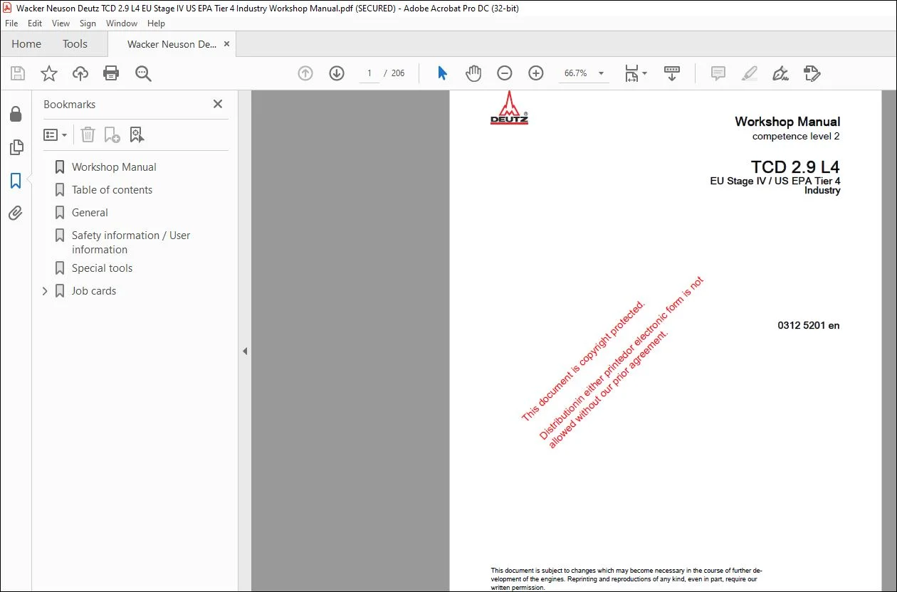
Wacker Neuson Deutz TCD 2.9 L4 EU Stage IV US EPA Tier 4 Industry Workshop Manual – PDF DOWNLOAD
Original price was: $75.95.$18.95Current price is: $18.95.
Wacker Neuson Deutz TCD 2.9 L4 EU Stage IV US EPA Tier 4 Industry Workshop Manual – PDF DOWNLOAD
Description
Wacker Neuson Deutz TCD 2.9 L4 EU Stage IV US EPA Tier 4 Industry Workshop Manual – PDF DOWNLOAD
DESCRIPTION:
Wacker Neuson Deutz TCD 2.9 L4 EU Stage IV US EPA Tier 4 Industry Workshop Manual – PDF DOWNLOAD
General :
The documentation of the workshop manual was created on the basis of the engine available on the editorial deadline- Due to further developments, there may be deviations from descriptions, illustrations and components.
- The valid documents published by DEUTZ AG (such as Service Info Technology, Technical Bulletin, Service Bulletins, Installation guidelines etc.) must be observed.
- The prescribed tightening specifications as well as the test and setting data must be taken into consideration and adhered to- The high safety and quality level of our engines is constantly guaranteed due to technical improvements and further developments. As a result, there may be deviations between the documentation and the current state of technological knowledge.
IMAGES PREVIEW OF THE MANUAL:
TABLE OF CONTENTS:
Wacker Neuson Deutz TCD 2.9 L4 EU Stage IV US EPA Tier 4 Industry Workshop Manual – PDF DOWNLOAD
Workshop Manual…………………………………………………………………………………………………….. 1
Table of contents…………………………………………………………………………………………………… 3
General……………………………………………………………………………………………………………. 6
Safety information / User information…………………………………………………………………………………. 7
Special tools………………………………………………………………………………………………………. 13
Job cards………………………………………………………………………………………………………….. 26
01 Crankcase/Front cover…………………………………………………………………………………………. 26
W 01-00-01 Check crankcase pressure……………………………………………………………………………. 26
W 01-17-01 Removing and installing the control valve…………………………………………………………….. 31
W 01-90-01 Sealing parts (crankcase, oil filler neck)……………………………………………………………. 34
W 01-90-23 Oil measuring device……………………………………………………………………………….. 35
W 01-90-32 Line (crankcase breather)…………………………………………………………………………… 36
02 Oil pan……………………………………………………………………………………………………… 38
W 02-01-01 Removing and installing the lubricating oil pan……………………………………………………….. 38
05 Crankshaft/Torsional vibration damper/………………………………………………………………………….. 44
W 05-02-03 Removing and installing the drive flange……………………………………………………………… 44
W 05-03-01 Removing and installing the flywheel (Fastening parts)…………………………………………………. 51
W 05-90-05 Fastening parts (Pulley – drive flange)………………………………………………………………. 53
08 Cylinder head………………………………………………………………………………………………… 54
W 08-00-01 Checking the compression pressure (when injectors are removed)………………………………………….. 54
W 08-01-01 Removing and installing the cylinder head cover……………………………………………………….. 60
09 Gear case/Gear drive………………………………………………………………………………………….. 62
W 09-01-01 Replacing the crankshaft sealing ring (Flywheel side)………………………………………………….. 62
W 09-02-03 Removing and installing the sealing cover…………………………………………………………….. 65
W 09-03-01 Removing and fitting the front cover (Fastening parts)…………………………………………………. 67
W 09-04-01 Replacing the crankshaft sealing ring (opposite side to flywheel)……………………………………….. 71
W 09-90-63 Oil pressure control valve………………………………………………………………………….. 74
15 Lubricating oil cooler/Lubricating oil filter……………………………………………………………………. 75
W 15-02-01 Removing and installing the lubricating oil cooler…………………………………………………….. 75
W 15-90-38 Lubricating oil filter installation………………………………………………………………….. 77
16 Lubricating oil pipe………………………………………………………………………………………….. 78
W 16-01-01 Removing and installing the oil suction pipe………………………………………………………….. 78
17 Injection pump/High pressure pump………………………………………………………………………………. 80
W 17-01-04 Removing and installing the high-pressure pump………………………………………………………… 80
19 Fuel injector/Injector………………………………………………………………………………………… 88
W 19-01-01 Removing and installing the injector…………………………………………………………………. 88
20 Fuel filter/Fuel pump…………………………………………………………………………………………. 95
W 20-90-16 Fuel pre-filter……………………………………………………………………………………. 95
W 20-90-17 Fuel filter……………………………………………………………………………………….. 97
W 20-90-20 Pressure sensor installation (Fuel pressure)………………………………………………………….. 99
W 20-90-40 Level sensor (Fuel pre-filter)……………………………………………………………………….101
W 20-90-47 Fuel supply pump (electric)………………………………………………………………………….102
21 Fuel pipes……………………………………………………………………………………………………104
W 21-04-01 Removing and installing the rail……………………………………………………………………..104
W 21-04-03 Removing and installing the pressure relief valve (Rail)………………………………………………..109
W 21-04-05 Removing and installing the rail pressure sensor……………………………………………………….112
W 21-05-05 Removing and installing the fuel line (injector, rail, high-pressure pump)………………………………..115
W 21-90-30 Fuel line (Quick coupling)…………………………………………………………………………..120
22 Air filter/Suction pipe/Charge air line………………………………………………………………………….122
W 22-01-01 Removing and installing the charge air line……………………………………………………………122
W 22-90-35 Intake nozzle (Exhaust turbocharger)………………………………………………………………….126
W 22-90-54 Charge air manifold…………………………………………………………………………………127
37 Coolant pump………………………………………………………………………………………………….128
W 37-03-01 Removing and installing the coolant pump………………………………………………………………128
W 37-90-13 V-belt pulley (Fastening parts, coolant pump)………………………………………………………….132
38 Coolant pipes/Thermostat housing………………………………………………………………………………..133
W 38-01-01 Removing and installing the thermostat………………………………………………………………..133
W 38-01-02 Checking the thermostat (when removed)………………………………………………………………..136
41 Exhaust pipe/Exhaust gas recirculation…………………………………………………………………………..138
W 41-01-01 Removing and installing the exhaust pipe………………………………………………………………138
W 41-05-01 Removing and installing the flutter valve……………………………………………………………..140
W 41-05-02 Removing and installing the exhaust gas recirculation module…………………………………………….144
W 41-05-03 Removing and installing exhaust gas recirculation valve…………………………………………………148
W 41-90-36 Exhaust manifold (Exhaust gas recirculation)…………………………………………………………..152
43 Exhaust gas turbocharger……………………………………………………………………………………….153
W 43-01-01 Removing and installing the exhaust gas turbocharger……………………………………………………153
W 43-04-01 Removing and installing the lubricating oil line (Exhaust turbocharger)…………………………………..156
W 43-05-01 Removing and installing the lubricating oil return line (upper partial section) (Exhaust turbocharger)……….159
W 43-05-02 Removing and installing the lubricating oil return line (lower partial section) (Exhaust turbocharger)……….162
44 Generator/Starter……………………………………………………………………………………………..166
W 44-02-01 Removing and installing the generator…………………………………………………………………166
W 44-90-42 Generator………………………………………………………………………………………….169
W 44-90-90 Starter……………………………………………………………………………………………170
48 Electric……………………………………………………………………………………………………..171
W 48-90-05 Fastening parts (Cable harness, transfer connector, crankcase)…………………………………………..171
W 48-90-20 Pressure sensor installation (Fuel pressure / lubricating oil pressure)…………………………………..172
W 48-90-68 Cable harness………………………………………………………………………………………174
49 Tools/Special tools……………………………………………………………………………………………175
W 49-01-03 Check cooling system for leaks……………………………………………………………………….175
W 49-02-01 Removing and installing turning gear/locking device…………………………………………………….178
51 Measuring instruments………………………………………………………………………………………….180
W 51-02-01 Removing and installing the speed sensor (Crankshaft)…………………………………………………..180
W 51-02-03 Removing and installing the speed sensor (Camshaft)…………………………………………………….182
W 51-08-01 Removing and installing pressure/temperature sensor (Charge air)…………………………………………184
W 51-08-01 Removing and installing pressure/temperature sensor (Charge air)…………………………………………186
W 51-09-01 Removing and installing the temperature sensor (Charge air)……………………………………………..190
W 51-90-20 Pressure sensor installation (Lubricating oil pressure)…………………………………………………193
W 51-90-20 Temperature sensor (Coolant)…………………………………………………………………………194
52 Connection housing…………………………………………………………………………………………….195
W 52-01-01 Installing and removing the connection housing…………………………………………………………195
71 Exhaust gas treatment………………………………………………………………………………………….197
W 71-10-01 Order of assembly (Installing catalyst) DOC (Diesel Oxidation Catalyst), SCR (Selective Catalytic Reduction)….197
W 71-90-09 Holder (Module size 13″)…………………………………………………………………………….203
W 71-90-09 Holder (Module size 5.66″)…………………………………………………………………………..204
W 71-90-09 Holder (Module size 8.5″)……………………………………………………………………………205
W 71-90-09 Holder (Module size 9.5″)……………………………………………………………………………206
PLEASE NOTE:
- This is the SAME exact manual used by your dealers to fix your vehicle.
- The same can be yours in the next 2-3 mins as you will be directed to the download page immediately after paying for the manual.
- Any queries / doubts regarding your purchase, please feel free to contact [email protected]
S.V