Wacker Neuson EZ17 Track excavator Service manual – PDF DOWNLOAD
Original price was: $78.00.$24.95Current price is: $24.95.
Wacker Neuson EZ17 Track excavator Service manual – PDF DOWNLOAD
Model E13-01
Edition 1.2
Document order number 1000294837
Language en
Description
Wacker Neuson EZ17 Track excavator Service manual – PDF DOWNLOAD
IMAGES PREVIEW OF THE MANUAL:
DESCRIPTION:
Wacker Neuson EZ17 Track excavator Service manual – PDF DOWNLOAD
1 Operation
1.1 Notices on this service manual
- This service manual contains important notices on how to perform regular maintenance and servicing work on the machine- Therefore, the service manual aims not only at new personnel, but it also serves as a reference for experienced personnel- The service man- ual helps to avoid hazardous situations and reduce repair costs and downtimes.
- Furthermore, the reliability and the service life of the machine will be increased by follow- ing the instructions in the service manual. Careful and prudent working is the best way to avoid accidents! Operational safety and readiness of the machine do not only depend on your skill, but also on maintenance and servicing of the machine.
- This is why regular maintenance and ser- vicing is absolutely necessary- Extensive maintenance and repair work must always be performed by a Wacker Neuson service center. Use only original spare parts for repairs. This ensures operational safety and readiness of your machine, and maintains its value-
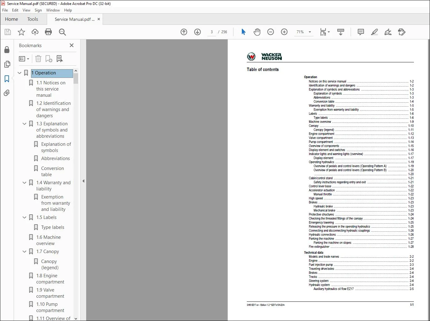
TABLE OF CONTENTS:
Wacker Neuson EZ17 Track excavator Service manual – PDF DOWNLOAD
1 Operation 12
1 1 Notices on this service manual 12
1 2 Identification of warnings and dangers 12
1 3 Explanation of symbols and abbreviations 13
Explanation of symbols 13
Abbreviations 13
Conversion table 14
1 4 Warranty and liability 15
Exemption from warranty and liability 15
1 5 Labels 16
Type labels 16
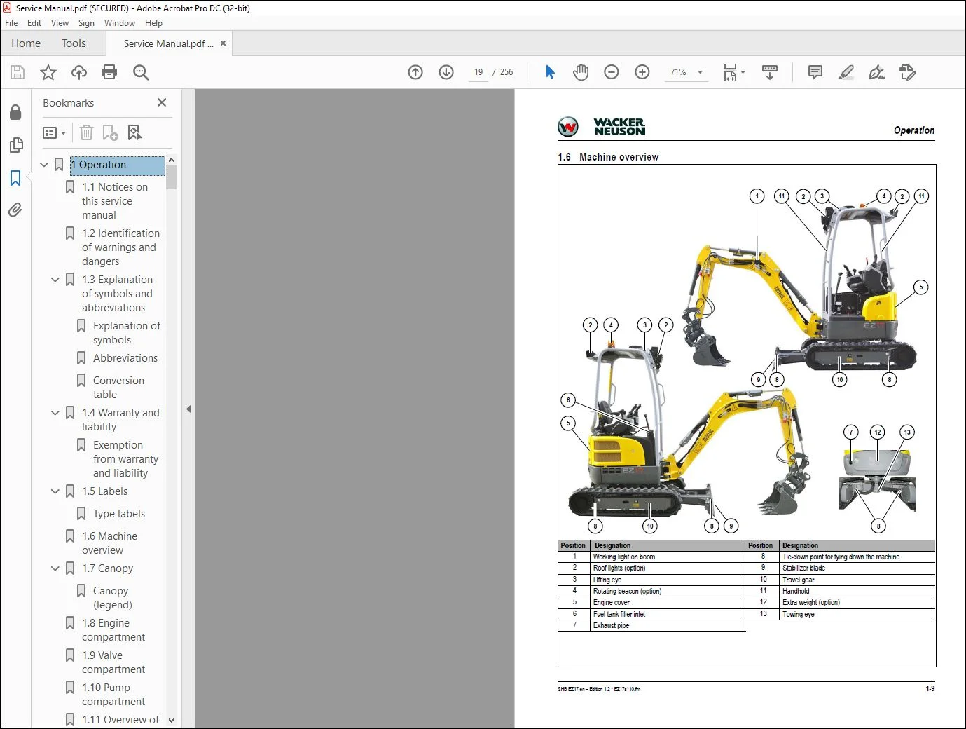
1 6 Machine overview 19
1 7 Canopy 20
Canopy (legend) 21
1 8 Engine compartment 22
1 9 Valve compartment 23
1 10 Pump compartment 24
1 11 Overview of components 25
1 12 Display element and switches 26
1 13 Indicator lights and warning lights (overview) 27
Display element 27
1 14 Operating hydraulics 29
Overview of pedals and control levers (Operating Pattern A) 29
Overview of pedals and control levers (Operating Pattern B) 30
1 15 Cabin/control stand 31
Safety instructions regarding entry and exit 31
1 16 Control lever base 32
1 17 Accelerator actuation 32
Manual throttle 32
1 18 High speed 33
1 19 Brakes 33
Hydraulic brake 33
Mechanical brake 33
1 20 Protective structures 34
1 21 Checking the threaded fittings of the canopy 34
1 22 Emergency lowering 35
1 23 Releasing the pressure in the operating hydraulics 35
1 24 Connecting and disconnecting hydraulic couplings 36
1 25 Hydraulic connections 36
1 26 Parking the machine 37
Parking the machine on slopes 37
1 27 Fire extinguisher 38
2 Technical data 40
2 1 Models and trade names 40
2 2 Engine 40
2 3 Fuel injection pump 41
2 4 Traveling drive/axles 42
2 5 Brakes 42
2 6 Tracks 42
2 7 Steering system 42
2 8 Hydraulic system 42
Auxiliary hydraulics oil flow EZ17 43
3rd control circuit oil flow EZ17 43
2 9 Speed 44
2 10 Coolant compound table 44
2 11 Ground clearance/ground pressure 44
2 12 Excavator forces 44
2 13 Cylinder speeds 44
2 14 Vibration 45
2 15 Electrical system 46
Electrical components 46
Fuses 46
Relays 46
Bulbs 46
2 16 Weight 47
Machine weight 47
Weight of attachments 47
2 17 Noise emissions 47
2 18 Powertilt (option) 47
2 19 Tightening torques 48
Diesel engine tightening torques 48
Model-specific tightening torques 48
General tightening torques 49
Tightening torques for high-resistance threaded fittings 51
2 20 Payload/lift capacity 51
2 21 Dimensions 52
Overview EZ17 52
2 22 Kinematics 54
2 23 Measuring live ring tolerance 55
3 Maintenance 58
3 1 Information on maintenance 58
Responsibilities and prerequisites 58
Important safety instructions on maintenance 58
3 2 Service package 58
3 3 Fluids and lubricants 59
Oil types for diesel engine (depending on temperature) 60
Oil types for hydraulic system (depending on temperature) 60
Important information regarding operation with biodegradable hydraulic oil 61
3 4 Maintenance label 62
Explanation of symbols on the maintenance label 63
3 5 Maintenance plan 64
3 6 Overview of maintenance areas 68
3 7 Maintenance accesses 69
Engine cover 69
Upper right cover 70
Lower right cover 71
Cover on the left 71
Raising the operator seat 72
Battery cover 72
3 8 Removing/installing the canopy 73
3 9 Fuel system 76
Important information regarding the fuel system 76
Diesel fuel specification 76
Handling fuel 77
Refueling 77
Emptying the fuel tank 78
Bleeding the fuel system 78
Checking the water separator 79
Emptying the water separator 79
Fuel filter 80
Checking the fuel filter 80
Emptying the fuel filter 81
Replacing the fuel filter 82
3 10 Engine lubrication system 83
Important information regarding the engine lubrication system 83
Checking the engine oil level 83
Adding engine oil 84
Changing engine oil 85
Replacing the engine-oil filter cartridge 86
3 11 Cooling system 88
Important information regarding the cooling system 88
Checking the coolant level 88
Adding coolant 89
Draining coolant 90
Cleaning the radiator 91
3 12 Air filter 92
Important information regarding the air filter 92
Dirt indicator 93
Replacing the air filter 94
Checking the air intake 95
3 13 Heating, ventilation and air conditioning system 95
3 14 Washer system 95
3 15 V-belt 96
Checking V-belt condition and tension 96
Replacing/retensioning the V-belt 96
3 16 Pressure check 99
General 99
Prerequisites for pressure check 99
Measurement connections (overview) 100
Checking pilot control pressure 100
Pressure reducing valve (PRV) 100
Checking the LS pressure limiting valve 101
Setting the LS pressure limiting valve on the main valve block 101
Setting the secondary pressure limiting valve (PLV) 101
Checking the secondary pressure limiting valve on the gear motor 102
3 17 Test report 103
3 18 Hydraulic system 105
Important information on the hydraulic system 105
Checking the hydraulic oil level 106
Adding hydraulic oil 106
Changing hydraulic oil 108
Replacing the hydraulic oil filter 109
Draining condensation water from the hydraulic oil reservoir 110
Checking the hydraulic system for leaks and general condition 110
3 19 Pilot control filter 111
3 20 Axles/traveling drive 112
Checking the oil level and adding oil 112
Draining oil 112
3 21 Tires/tracks 113
Important information regarding the tracks 113
Checking track tension 113
Correcting track tension 114
3 22 Maintenance of attachments 115
Important information regarding maintenance of attachments 115
3 23 Maintenance of options 115
Joint rod (lifting eye) and load hook 115
3 24 Lubrication work 116
Preparing lubrication 116
3 25 Lubrication plan 117
Live ring (ball bearing) 119
Control lever base 120
3 26 Electrical system 121
Important information regarding the electrical system 121
Fuses and relays 121
Battery charge condition 122
Charging the battery 122
Replacing the battery 122
3 27 Cleaning and maintenance 123
Important information on cleaning and maintenance 123
Use of solvents 124
Cleaning inside the machine 124
Cleaning outside the machine 124
Cleaning the engine compartment 124
Cleaning the seat belt 125
Cleaning the shatter protection 125
Threaded fittings and attachments 125
3 28 Putting out of operation/back into operation 126
Putting out of operation temporarily 126
Putting back into operation 126
3 29 Permanently putting out of operation 127
Disposal 127
3 30 Resetting the maintenance meter 127
4 Engine 130
4 1 Overview of engine 3TNV76-NNS (TIER IV final up to 2012) 130
4 2 Fuel system 132
4 3 Cooling system 133
4 4 Checking and adjusting valve clearance 134
4 5 Tightening order for cylinder head bolts 136
Order for removing the cylinder-head bolts: 136
Order for installing the cylinder-head bolts: 136
4 6 Checking the injection nozzles 137
Pressure check 137
4 7 Checking the nozzle jet 138
4 8 Injection time 138
Checking injection time 138
Setting injection time 140
4 9 Removing and installing the injection pump 141
Removing the injection pump 141
Fitting the fuel injection pump 142
4 10 Measuring and adjusting the engine speed 143
4 11 Compression 144
4 12 Checking the coolant thermostat 144
4 13 Checking the temperature sensor 145
4 14 Oil pressure switch 145
4 15 Checking the coolant circuit 145
4 16 Cleaning the cooling water channels 146
4 17 Coolant and fuel hoses 146
4 18 Crankcase vent 146
4 19 Replacing the glow plugs 146
4 20 Engine malfunctions 147
4 21 Overview of engine 3TNV80F-SNNS (TIER IV final from 2012) 149
4 22 Fuel system 151
4 23 Cooling system 152
4 24 Altitude-dependent output reduction 153
4 25 Checking and adjusting valve clearance 154
4 26 Tightening order for cylinder head bolts 156
Order for removing the cylinder-head bolts: 156
Order for installing the cylinder-head bolts: 156
4 27 Checking the injection nozzles 157
Pressure check 157
4 28 Checking the nozzle jet 158
4 29 Injection time 158
Checking injection time 158
Setting injection time 160
4 30 Removing and installing the injection pump 161
Removing the injection pump 161
Fitting the fuel injection pump 162
4 31 Measuring and adjusting the engine speed 164
4 32 Compression 164
4 33 Checking the coolant thermostat 165
4 34 Checking the temperature sensor 165
4 35 Oil pressure switch 166
4 36 Checking the coolant circuit 166
4 37 Cleaning the cooling water channels 167
4 38 Coolant and fuel hoses 167
4 39 Crankcase vent 167
4 40 Replacing the glow plugs 167
4 41 Engine malfunctions 168
5 Hydraulic system 172
5 1 How the load-sensing system works 173
5 2 Overview of components 174
Hydraulic reservoir components 175
5 3 Hydraulic pump 176
Variable displacement pump design 176
Bleeding the hydraulic system 177
Pilot oil supply unit 178
Bladder type accumulator 179
Troubleshooting on the hydraulic pump 179
5 4 Main valve block 180
Functions 180
Connections 182
5 5 Traveling drive 183
Function 184
5 6 Swivel unit 186
Functional description 186
Swivel unit overview 187
Exploded view of secondary pressure limiting valve 187
Overview of swivel unit 188
Replacing the seals 189
5 7 Swivel joint 192
5 8 Valves 193
Proportional valve (option) 193
8/2 directional valve (option) 193
Hydraulic quickhitch valve (option) 193
Hydraulic oil reservoir service valve 194
5 9 Breather filter (hydraulic oil reservoir) 194
5 10 Test specifications for measuring cylinder speeds 195
5 11 Troubleshooting the hydraulic system 196
6 Electrical system 198
6 1 Ohm’s Law (current, voltage, resistance); power 198
6 2 Measuring equipment, measuring methods 198
6 3 Relays 199
Use, mode of function 199
6 4 Electrical components 200
Fuses 200
Relays 200
Bulbs 200
Alternator 201
Starter 201
Socket 201
Rotating beacon (option) 202
6 5 Main wiring harness legend 204
6 6 Main wiring harness 207
6 7 Proportional controls wiring harness (option) 208
6 8 Travel signal wiring harness (option) 209
7 Diagrams 0
7 1 Hydraulics diagram legend (up to serial number WNCE1301CPAL01309) 212
8 Options 222
8 1 Counterweight 222
Technical data 222
8 2 Long stick 222
Technical data 222
8 3 Safe load indicator 223
Setting the pressure switch 225
8 4 Electro-proportional controls 226
8 5 3rd control circuit – AUX II 227
Diagram 227
8 6 Hydraulic quickhitch valve 228
Hydraulic quickhitch pressure variants 229
Easy Lock emergency unlocking 231
8 7 Grab control circuit 232
8 8 Hose burst valve 233
8 9 Immobilizer 234
8 10 Engine oil service valve 235
Function 235
8 11 Telematic 236
Connections 236
Functional check/diode 236
9 PowerTilt PTS4 5 238
9 1 General instructions 238
General safety instructions 238
Checking the product 239
Decompression valve 239
Testing the hydraulic system of the machine 239
Specifications/requirements 240
9 2 Tools 241
Making a tool for removing the seals 242
9 3 Separating the bucket or equipment from the PowerTilt swivel device 242
9 4 Separating the PowerTilt swivel device from the machine 242
9 5 Individual components 243
9 6 Replacement sealing kit A and bearing kit B 244
Dismantling the base blocks 244
Removing the end cap 245
Removing the shaft 245
Removing the piston tube body 246
Removing all seals (kit A), shaft bearing and pressure disks (kit B) 247
Fitting seals (kit A), shaft bearing and pressure disks (kit B) 248
Fitting the piston tube body 248
Fitting the shaft 249
Installing the end cap 249
Fitting the base blocks 250
9 7 Lubrication and tests 250
Lubrication 250
Test 250
9 8 Replacing the decompression valve 251
9 9 Securing the PowerTilt swivel device on the machine 251
9 10 Fitting a bucket or equipment onto the PowerTilt swivel device 252
9 11 Adjusting the play on the PowerTilt 252
9 12 Troubleshooting 253
Contact us: [email protected]
https://vimeo.com/738864803
PLEASE NOTE:
- This is the SAME MANUAL used by the dealerships to diagnose your vehicle
- No waiting for couriers / posts as this is a PDF manual and you can download it within 2 minutes time once you make the payment.
- Your payment is all safe and the delivery of the manual is INSTANT – You will be taken to the DOWNLOAD PAGE.
- So have no hesitations whatsoever and write to us about any queries you may have : heydownloadss @gmail.com
S.m