Wacker Neuson EZ38 Track excavator Service manual – PDF DOWNLOAD
Original price was: $89.00.$24.95Current price is: $24.95.
Wacker Neuson EZ38 Track excavator Service manual – PDF DOWNLOAD
Model E07-02
Edition 1.2
Document order number 1000333445
Language en
Description
Wacker Neuson EZ38 Track excavator Service manual – PDF DOWNLOAD
IMAGES PREVIEW OF THE MANUAL:
DESCRIPTION:
Wacker Neuson EZ38 Track excavator Service manual – PDF DOWNLOAD
1 Operation
1.1 Information on this service manual
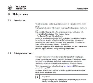
- This service manual contains important information on how to service the machine correctly and economically. The service manual helps to avoid hazardous situations and reduce repair costs and downtimes.
- Furthermore, the reliability and the service life of the machine will be increased by following the instructions in the Operator’s Manual. Careful and prudent working is the best way to avoid accidents! Operational safety and readiness of the machine do not only depend on your skill, but also on maintenance and servicing of the machine.
- This is why regular maintenance and servicing is absolutely necessary. Extensive maintenance and repair work must always be performed by a Wacker Neuson service center. Use only original spare parts for repairs. This ensures operational safety and readiness of your machine, and maintains its value.
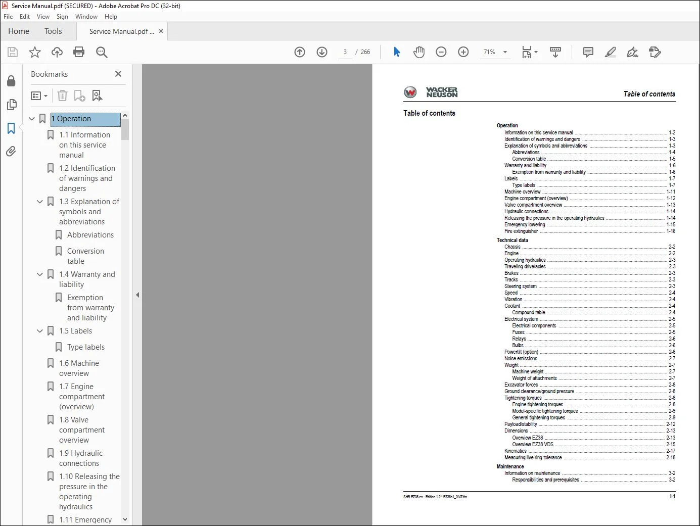
TABLE OF CONTENTS:
Wacker Neuson EZ38 Track excavator Service manual – PDF DOWNLOAD
Operation
Information on this service manual 1-2
Identification of warnings and dangers 1-3
Explanation of symbols and abbreviations 1-3
Abbreviations 1-4
Conversion table 1-5
Warranty and liability 1-6
Exemption from warranty and liability 1-6
Labels 1-7
Type labels 1-7
Machine overview 1-11
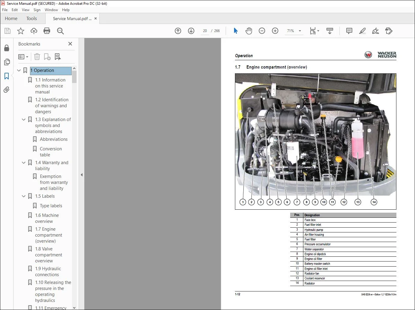
Engine compartment (overview) 1-12
Valve compartment overview 1-13
Hydraulic connections 1-14
Releasing the pressure in the operating hydraulics 1-14
Emergency lowering 1-15
Fire extinguisher 1-16
Technical data
Chassis 2-2
Engine 2-2
Operating hydraulics 2-3
Traveling drive/axles 2-3
Brakes 2-3
Tracks 2-3
Steering system 2-3
Speed 2-4
Vibration 2-4
Coolant 2-4
Compound table 2-4
Electrical system 2-5
Electrical components 2-5
Fuses 2-5
Relays 2-6
Bulbs 2-6
Powertilt (option) 2-6
Noise emissions 2-7
Weight 2-7
Machine weight 2-7
Weight of attachments 2-7
Excavator forces 2-8
Ground clearance/ground pressure 2-8
Tightening torques 2-8
Engine tightening torques 2-8
Model-specific tightening torques 2-9
General tightening torques 2-9
Payload/stability 2-12
Dimensions 2-13
Overview EZ38 2-13
Overview EZ38 VDS 2-15
Kinematics 2-17
Measuring live ring tolerance 2-18
Maintenance
Information on maintenance 3-2
Responsibilities and prerequisites 3-2
Table of contents
I-2 SHB EZ38 en – Edition 12 * EZ38s1_0IVZfm
Table of contents
Important safety instructions on maintenance 3-2
Fluids and lubricants 3-3
Oil types for diesel engine (depending on temperature) 3-4
Oil types for hydraulic system (depending on temperature) 3-5
Important information regarding operation with biodegradable oil 3-5
Maintenance overview 3-6
Maintenance label 3-6
Explanation of symbols on the maintenance label 3-7
Lubrication work 3-8
Preparing lubrication 3-8
Lubrication plan 3-9
Maintenance plan 3-1
Maintenance accesses 3-5
Engine cover 3-5
Valve compartment 3-6
Fuse box 3-6
Raising/lowering the cabin 3-6
Lowering the cabin 3-8
Fuel system 3-10
Important information regarding the fuel system 3-10
Diesel fuel specification 3-10
Refueling 3-10
Bleeding the fuel system 3-13
Checking the water separator 3-13
Emptying the water separator 3-14
Emptying the fuel filter 3-14
Replacing the fuel filter 3-15
Engine lubrication system 3-16
Important information regarding the engine lubrication system 3-16
Checking the engine oil level 3-16
Adding engine oil 3-17
Changing engine oil 3-18
Replacing the engine-oil filter cartridge 3-19
Cooling system 3-21
Checking the coolant level 3-21
Adding coolant 3-22
Draining coolant 3-23
Cleaning the radiator 3-24
Air filter 3-25
Important information regarding the air filter 3-25
Air filter monitoring 3-25
Replacing the air filter 3-26
Checking the air intake 3-27
V-belt 3-28
Checking the V-belt tension of the alternator 3-28
Retensioning the alternator V-belt 3-29
Replacing the alternator V-belt 3-30
Checking the V-belt tension of the air conditioning system (option) 3-31
Replacing the V-belt of the air conditioning system (option) 3-31
Heating/ventilation/air conditioning 3-32
Maintenance on the air conditioning system 3-32
Checking/replacing the fresh-air filter of the heating/air conditioning 3-32
Replacing the crankcase breather filter 3-33
Washer system 3-34
Important information regarding the washer system 3-34
Checking the fluid level and adding fluid 3-34
Pressure check 3-35
SHB EZ38 en – Edition 12 * EZ38s1_0IVZfm I-3
Table of contents
General 3-35
Prerequisites for pressure check 3-35
Preparations 3-35
Measurement connections (overview) 3-36
Overview of primary pressure limiting valves 3-36
Checking pilot control pressure 3-37
Pressure check of variable displacement pump P1 3-38
Pressure check of variable displacement pump P2 3-39
Pressure check of gear pump P3 3-40
Secondary pressure limiting valve of the gear motor 3-40
Test report 3-41
Hydraulic system 3-43
Important information on the hydraulic system 3-43
Checking the hydraulic oil level 3-44
Adding hydraulic oil 3-44
Changing hydraulic oil 3-45
Changing the hydraulic oil filter element 3-46
Draining condensation water from the hydraulic oil reservoir 3-47
Checking the hydraulic system for leaks 3-48
Checking the condition and age of hydraulic hoses 3-48
Axles/traveling drive 3-49
Important information on axles/traveling drive 3-49
Checking the oil level and adding oil 3-49
Draining oil 3-49
Tires/tracks 3-50
Important information regarding the tracks 3-50
Checking track tension 3-50
Correcting track tension 3-51
Replacing the tracks 3-52
Maintenance of attachments 3-53
Important information regarding maintenance of attachments 3-53
Maintenance of options 3-53
Joint rod (lifting eye) and load hook 3-53
Cleaning and maintenance 3-53
Exhaust gas treatment 3-53
Machine preservation 3-53
Electrical system 3-54
Important information regarding the electrical system 3-54
Fuses and relays 3-54
Battery charge condition 3-55
Charging the battery 3-55
Replacing the battery 3-55
Engine
Engine 3TNV88-BPNS 4-2
Fuel system 4-4
Removing the cylinder-head cover 4-5
Checking and adjusting valve clearance 4-5
Tightening order for cylinder head bolts 4-6
Checking the injection nozzles 4-7
Pressure check 4-7
Checking the nozzle jet 4-7
Injection time 4-8
Checking injection time 4-8
Setting injection time 4-9
Replacement of fuel injection pump 4-10
Adjusting engine speed 4-11
I-4 SHB EZ38 en – Edition 12 * EZ38s1_0IVZfm
Table of contents
Compression 4-11
Checking the coolant thermostat 4-12
Checking the thermal switch 4-12
Oil pressure switch 4-13
Checking the coolant circuit 4-13
Engine malfunctions 4-14
Engine 3TNV88F-EPNS (Tier IV) 4-17
Fuel system 4-19
Removing the cylinder-head cover 4-21
Checking and adjusting valve clearance 4-22
4-23
Tightening order for cylinder head bolts 4-24
Checking the injection nozzles 4-25
Pressure check 4-25
Checking the nozzle jet 4-26
Injection time 4-26
Checking injection time 4-26
Setting injection time 4-28
Compression 4-29
Checking the coolant temperature sensor 4-30
Checking the coolant thermostat 4-30
Oil pressure switch 4-30
Checking the coolant circuit 4-31
Engine malfunctions 4-32
Hydraulic system
Hydraulic pump PVD-1B-32BP-11G5-4904A / PVD-1B-32BCP-11G5-5596Z 5-2
Pump unit: exploded view 5-4
Diagram 5-5
Pilot oil supply unit 5-6
Main valve block 5-7
Connections 5-7
Legend 5-8
Main valve block diagram 5-9
Pressure limiting valves 5-10
Pump assignment 5-11
Drive counterbalancing system 5-12
Pump assignment for drive counterbalancing 5-12
Regeneration – stick section 5-13
Bucket pre-tension 5-13
Flow rate adjustment of auxiliary hydraulics 5-14
Pilot valves 5-15
Joystick 5-15
Pilot valve (machine travel) 5-16
Valves 5-17
7/2 directional valve (changeover valve) 5-17
Changeover valve for SAE/ISO controls (option) 5-18
2-fold proportional valve (option) 5-19
Hydraulic oil reservoir service valve 5-20
Traveling drive 5-21
Functions 5-22
Exploded view of traveling drive 5-23
Swivel unit 5-24
Parking brake/multidisk brake function 5-25
Swivel joint 5-28
Sealing 5-28
Swivel joint VDS (option) 5-29
SHB EZ38 en – Edition 12 * EZ38s1_0IVZfm I-5
Table of contents
Breather filter 5-30
Malfunctions in the hydraulic system 5-31
Electrical system
Ohm’s Law (current, voltage, resistance); power 6-2
Measuring equipment, measuring methods 6-2
Cable color coding 6-3
Relays 6-4
Use, mode of function 6-4
Socket 6-4
Alternator 6-4
Starter 6-5
Cabin switches wiring harness (legend) 6-8
Cabin switches wiring harness 6-9
Legend: engine/chassis wiring harness (Yanmar 3TNV88-BPNS) 6-10
Engine/chassis wiring harness (Yanmar 3TNV88-BPNS) 6-12
Legend: engine/chassis wiring harness (Yanmar 3TNV88F-EPNS) 6-13
Engine/chassis wiring harness (Yanmar 3TNV88F-EPNS) 6-15
Legend: seat console wiring harness (Yanmar 3TNV88-BPNS) 6-16
Seat console wiring harness (Yanmar 3TNV88-BPNS) 6-18
Legend: seat console wiring harness (Yanmar 3TNV88F-EPNS) 6-19
Seat console wiring harness (Yanmar 3TNV88F-EPNS) 6-21
Cabin wiring harness (legend) 6-22
Cabin wiring harness 6-23
Cabin roof wiring harness 6-24
Canopy lights wiring harness 6-25
Proportional controls wiring harness (option) 6-26
Fuel-filling pump wiring harness (option) 6-27
Immobilizer wiring harness (option) 6-28
Rotating beacon cable 6-29
Boom light cable 6-30
Wiring harness for output regulation (from serial number WNCE0702CPAL00901)
6-31
Hydraulics diagram 7-2
Hydraulics diagram (legend) 7-2
Hydraulics diagram 7-3
Hydraulics diagram option 7-4
Main valve block 7-5
Diagram 7-5
Electrical diagrams 7-6
Electrical diagram 1 7-7
Electrical diagram 2 7-8
Electrical diagram for output regulation (from serial number WNCE0702CPAL00901)
7-9
Electrical diagram Tier IV ECO 7-10
Options
Air conditioning 8-2
Specific safety instructions 8-2
Technical data 8-2
Components 8-4
Compressor 8-5
Filling up the air conditioning system 8-6
Maintenance 8-7
Troubleshooting 8-8
Counterweight 8-10
Technical data 8-10
Long stick 8-10
I-6 SHB EZ38 en – Edition 12 * EZ38s1_0IVZfm
Table of contents
Technical data 8-10
Safe load indicator 8-11
Safe load indicator pressure switch 8-11
Setting the pressure switch 8-12
Hydraulic quickhitch valve 8-14
Hydraulic quickhitch pressure variants 8-15
Easy Lock emergency unlocking 8-17
Immobilizer 8-18
Service valve 8-19
Function 8-19
Telematic 8-20
Connections 8-20
Functional check/diode 8-20
Special tools PAL
Need help? Contact: [email protected]
https://vimeo.com/735683432
PLEASE NOTE:
- This is the SAME MANUAL used by the dealerships to diagnose your vehicle
- No waiting for couriers / posts as this is a PDF manual and you can download it within 2 minutes time once you make the payment.
- Your payment is all safe and the delivery of the manual is INSTANT – You will be taken to the DOWNLOAD PAGE.
- So have no hesitations whatsoever and write to us about any queries you may have : heydownloadss @gmail.com
S.M