Wincor Nixdorf ProCash 2000 Service Manual PDF DOWNLOAD
Original price was: $120.00.$20.95Current price is: $20.95.
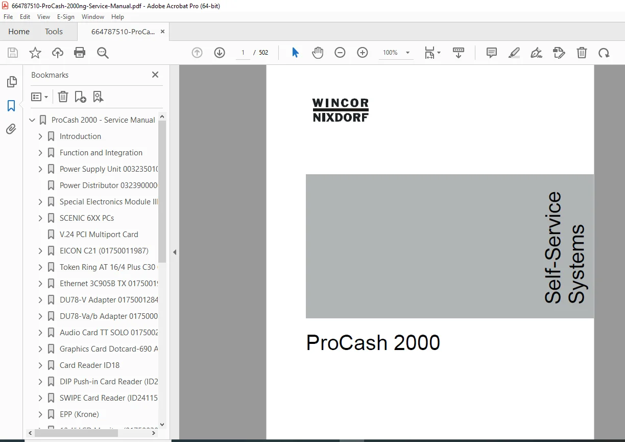
Detailed Wincor Nixdorf ProCash 2000 service manual PDF covering technical data, function integration, component descriptions, removal/installation procedures, and maintenance for ATM self-service systems. Includes ProCash 2000 cash-out module troubleshooting, Wincor Nixdorf ATM special electronics module guide, ProCash 2000 LCD monitor maintenance instructions, ProCash 2000 card reader service details, and error handling. 502 pages with diagrams, pin assignments, and block diagrams for technicians.
Description
Wincor Nixdorf ProCash 2000 Service Manual PDF DOWNLOAD
Description
This comprehensive Wincor Nixdorf ProCash 2000 service manual PDF is an indispensable resource for technicians servicing ProCash 2000 ATM self-service systems. Document number 01750030886 A, it provides in-depth coverage of system overview, safety precautions, technical specifications, block diagrams, power supply units, special electronics, PCs, monitors, printers, card readers, keyboards, UPS, cash-out modules, cameras, operator panels, and user guidance. Key sections emphasize practical guidance for ProCash 2000 cash-out module troubleshooting, including error codes, sensor overviews, and cash path descriptions for frontload/rearload variants. The Wincor Nixdorf ATM special electronics module guide details controls, pin assignments, and UPS integration for reliable operation.
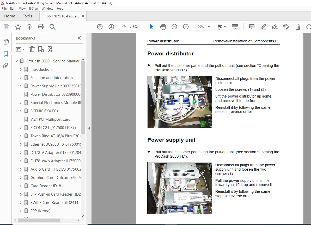
The manual supports Wincor Nixdorf ProCash 2000 removal and installation procedures with step-by-step instructions for components like LCD monitors (10.4″, 12.1″, 15″), card readers (ID18, DIP, SWIPE), printers (ND98, ND9C/ND9E), and power distributors in both rearload (RL) and frontload (FL) configurations. ProCash 2000 LCD monitor maintenance instructions cover inverter settings, backlight replacement, and interface cards for optimal display performance. Additional features include ProCash 2000 card reader service details for firmware, cleaning, and pin assignments, alongside maintenance tips for approved materials and test options.
Structured for efficient reference, it includes:
- Table of Contents (Neatly categorized from pages C-1 to C-18):
| Chapter | Title | Page |
|---|---|---|
| – | Introduction | 1-1 |
| – | Symbols used in this manual | 1-1 |
| – | Important safety precautions | 1-2 |
| – | General power interrupt | 1-4 |
| – | Description of the device | 1-5 |
| – | Function and use | 1-5 |
| – | Structure of the manual | 1-5 |
| – | Outline | 1-5 |
| – | Supplementary documentation | 1-6 |
| – | Manual release | 1-6 |
| – | Technical data | 1-7 |
| – | Electrical characteristics of the supply network | 1-7 |
| – | Device conditions | 1-7 |
| – | Installation conditions | 1-8 |
| – | Ambient conditions in accordance with DIN EN 60721 (IEC 721) | 1-9 |
| – | Mechanical conditions according to DIN IEC 721 | 1-9 |
| – | Noise emission in accordance with DIN EN 27779 | 1-10 |
| – | Compliance with standards and certifications | 1-11 |
| – | Function and Integration | 2-1 |
| – | Block diagrams | 2-1 |
| – | System wiring diagram | 2-2 |
| – | Cash-out module | 2-3 |
| – | Portrait camera | 2-3 |
| – | Audio Standard | 2-3 |
| – | Powersave feature | 2-4 |
| – | Power supply | 2-5 |
| – | Mains voltage | 2-5 |
| – | Direct voltage supply | 2-5 |
| – | Special electronics | 2-7 |
| – | Functions used | 2-7 |
| – | Signal assignment of user guidance | 2-7 |
| – | Sound system Audio Standard | 2-8 |
| – | CCTV monitoring | 2-8 |
| – | SOP button | 2-8 |
| – | System unit (PC) | 2-9 |
| – | Overview | 2-9 |
| – | LPT assignment | 2-9 |
| – | COM assignment | 2-10 |
| – | SCENIC PC system settings | 2-11 |
| – | Overview of PC cards | 2-13 |
| – | Monitors | 2-14 |
| – | Operating the flat displays | 2-15 |
| – | Microswitch and jumper positions | 2-15 |
| – | Setting the graphics card | 2-16 |
| – | Setting the interface card | 2-17 |
| – | PL adapter settings | 2-17 |
| – | Printers | 2-18 |
| – | Card reader ID18 | 2-18 |
| – | Card reader ID24 | 2-18 |
| – | Keyboards and keypads | 2-19 |
| – | Uninterruptible power supply unit (UPS) | 2-19 |
| – | Power Supply Unit 00323501000 | 3-1 |
| – | Description | 3-1 |
| – | Operating state indicator | 3-1 |
| – | Power failure | 3-1 |
| – | Technical data | 3-2 |
| – | Pin assignment | 3-2 |
| – | Input voltages | 3-4 |
| – | Output voltages | 3-4 |
| – | Miscellaneous | 3-4 |
| – | Power Distributor 0323900000 | 3-5 |
| – | Special Electronics Module III 01750003214 | 3-7 |
| – | Controls and indicators | 3-7 |
| – | Mode of operation | 3-7 |
| – | Switch-on characteristics | 3-8 |
| – | Controlling the power supply | 3-8 |
| – | UPS mode | 3-9 |
| – | System environment diagram | 3-10 |
| – | Views of the special electronics | 3-11 |
| – | Pin assignment | 3-12 |
| – | Power source, power supply unit control | 3-12 |
| – | Power distributor | 3-12 |
| – | Internal inputs/outputs I | 3-13 |
| – | Customer-specific inputs/outputs | 3-14 |
| – | V.24 control of the SE | 3-15 |
| – | Softkeys on the left | 3-15 |
| – | Softkeys on the right | 3-15 |
| – | Control of operator prompts (illuminated arrows) | 3-16 |
| – | PIN keyboard matrix | 3-17 |
| – | 2 externally accessible jumpers | 3-17 |
| – | Internal inputs/outputs II | 3-18 |
| – | SCENIC 6XX PCs | 4-1 |
| – | Overview of PC variants | 4-1 |
| – | Supplied software | 4-1 |
| – | Technical data | 4-2 |
| – | SCENIC 651 PII/400 IDE CD-R64 MB | 4-2 |
| – | SCENIC 651 PII/400 SCSI CD-R64 MB | 4-4 |
| – | SCENIC 661 PIII/450 IDE CD-R64 MB | 4-6 |
| – | SCENIC 661 PIII/550 IDE CD-R64 MB | 4-8 |
| – | ATX system board D1107 | 4-10 |
| – | Resource table | 4-12 |
| – | PCI bus interrupts | 4-13 |
| – | Settings with switches | 4-14 |
| – | Switch 1 | 4-15 |
| – | Switch 2: Recover system BIOS | 4-15 |
| – | Switch 3: Write protection for floppy drive | 4-15 |
| – | Switch 4 | 4-15 |
| – | Switches 5 to 8: Setting the clock frequency | 4-16 |
| – | Pentium II with 66 MHz Front Side Bus | 4-16 |
| – | Celeron with 66 MHz Front Side Bus | 4-17 |
| – | Pentium II with 100 MHz Front Side Bus | 4-17 |
| – | Pentium III with 100 MHz Front Side Bus | 4-17 |
| – | Extensions | 4-18 |
| – | Exchanging the processor | 4-20 |
| – | Inserting the processor | 4-21 |
| – | Removing the processor | 4-21 |
| – | Upgrading main memory | 4-22 |
| – | Inserting the memory module | 4-23 |
| – | Removing the memory module | 4-23 |
| – | Exchanging the lithium battery | 4-24 |
| – | CMOS-SETUP | 4-25 |
| – | Bios version: V4.06 R 1.04.1107 | 4-25 |
| – | Main | 4-25 |
| – | Main > Hard Disk 1 | 4-25 |
| – | Main > Boot Options | 4-26 |
| – | Advanced | 4-26 |
| – | Advanced > Cache Memory | 4-27 |
| – | Advanced > Peripheral Configuration | 4-27 |
| – | Advanced > PCI Configuration | 4-28 |
| – | Advanced > Advanced System Configuration | 4-28 |
| – | Advanced > Power On/Off | 4-29 |
| – | Advanced > System Management | 4-29 |
| – | Security | 4-30 |
| – | Power | 4-30 |
| – | Exit | 4-31 |
| – | V.24 PCI Multiport Card | 4-33 |
| – | EICON C21 (01750011987) | 4-35 |
| – | Item numbers incl. SW | 4-35 |
| – | Card accessories | 4-37 |
| – | Required hardware resources | 4-38 |
| – | Overview of possible I/O addresses | 4-38 |
| – | Interrupt setting | 4-39 |
| – | Installation | 4-40 |
| – | OSI gateway for DOS | 4-40 |
| – | OS/2, OSI or SNA Gateway | 4-42 |
| – | Windows NT 4.0: Connection for Windows NT V4R2 | 4-44 |
| – | Automatic installation | 4-45 |
| – | Manual installation | 4-47 |
| – | Configuration of the WAN Services | 4-50 |
| – | Testing the card with ECTEST | 4-53 |
| – | Technical data | 4-54 |
| – | Pin assignment | 4-55 |
| – | Appendix | 4-56 |
| – | Example for DOS | 4-56 |
| – | Example: OSI Gateway (depending on the above directory entry) | 4-56 |
| – | Examples for OS/2 | 4-56 |
| – | Token Ring AT 16/4 Plus C30 01750012715 | 4-61 |
| – | Hardware settings | 4-62 |
| – | Factory defaults | 4-62 |
| – | Overview of possible settings | 4-62 |
| – | Configuration program | 4-63 |
| – | Configuring the card | 4-64 |
| – | Command table | 4-65 |
| – | Software switches | 4-66 |
| – | SMARTLSP.EXE driver | 4-68 |
| – | Creating the SMARTLSP.EXE driver | 4-68 |
| – | Ethernet 3C905B TX 01750019090 | 4-71 |
| – | Introduction | 4-71 |
| – | DOS configuration program | 4-73 |
| – | Adjustment of the card | 4-74 |
| – | DU78-V Adapter 0175001284 | 4-75 |
| – | Setting | 4-76 |
| – | I/O address | 4-76 |
| – | DMA selection | 4-77 |
| – | Interrupt choice | 4-78 |
| – | Default setting | 4-79 |
| – | Interface | 4-80 |
| – | Signal assignment universal DT interface | 4-80 |
| – | DU78-Va/b Adapter 01750007738/-25516 | 4-81 |
| – | Setting | 4-81 |
| – | I/O address | 4-83 |
| – | DMA selection | 4-83 |
| – | Interrupt choice | 4-84 |
| – | Setting example | 4-85 |
| – | Interface | 4-85 |
| – | Signal assignment universal DT interface | 4-85 |
| – | Audio Card TT SOLO 01750022769 | 4-87 |
| – | Technical data | 4-87 |
| – | Graphics Card Dotcard-690 AGP | 4-89 |
| – | Introduction | 4-89 |
| – | Resources | 4-89 |
| – | DIP switches, connectors and jumpers | 4-90 |
| – | Description of connectors | 4-91 |
| – | Connector X8: External PanelLink | 4-91 |
| – | Connector X9: Connection for analogue monitor | 4-91 |
| – | Connector X2: Connection for separate 12 V supply | 4-91 |
| – | Jumper settings | 4-92 |
| – | JP4: BIOS access | 4-92 |
| – | JP5: DISPON Polarity | 4-92 |
| – | JP9: 12 V power supply | 4-93 |
| – | JP11 and JP12: Display CLK source | 4-93 |
| – | JP19: 3.3 V Core voltage | 4-94 |
| – | Potentiometer R117 | 4-94 |
| – | Adjusting the PanelLink signal peak | 4-94 |
| – | Setting the DIP switches | 4-95 |
| – | Fuse | 4-98 |
| – | Pin assignment | 4-98 |
| – | Connector X9 | 4-98 |
| – | Connector X2 | 4-98 |
| – | Connector X8 | 4-99 |
| – | Card Reader ID18 | 5-1 |
| – | Devices with hard-coded firmware | 5-2 |
| – | Devices with firmware download | 5-3 |
| – | Position of components | 5-5 |
| – | Pin assignment | 5-6 |
| – | RS232C Interface | 5-6 |
| – | I/O Port | 5-7 |
| – | Power supply | 5-8 |
| – | Maintenance and service | 5-9 |
| – | Cleaning and test utilities | 5-9 |
| – | Test utilities | 5-9 |
| – | Cleaning utilities | 5-9 |
| – | Spare parts | 5-9 |
| – | Technical data | 5-10 |
| – | DIP Push-in Card Reader (ID24102114) | 5-11 |
| – | System connection | 5-12 |
| – | Technical data | 5-13 |
| – | SWIPE Card Reader (ID24115214) | 5-15 |
| – | Schematic diagram | 5-16 |
| – | System connection | 5-17 |
| – | Technical data | 5-18 |
| – | Cleaning | 5-18 |
| – | EPP (Krone) | 5-19 |
| – | Description | 5-19 |
| – | Maintenance operations | 5-20 |
| – | Replacing the EPP in the event of an error | 5-20 |
| – | Replacing the battery | 5-20 |
| – | Battery type | 5-21 |
| – | Pin assignment | 5-21 |
| – | Pin assignment (9 pin M, D SUB) | 5-21 |
| – | 10.4“ LCD Monitor (01750020552) | 6-1 |
| – | Important safety precautions | 6-1 |
| – | Module view and integration | 6-2 |
| – | Technical data LCD | 6-3 |
| – | Mechanical and environmental conditions | 6-3 |
| – | Electrical properties (maximum values) | 6-3 |
| – | Electrical properties of background lighting | 6-4 |
| – | Pin assignment: Interface | 6-5 |
| – | Pin assignment: Lamp connector | 6-6 |
| – | Inverter | 6-7 |
| – | Technical data | 6-7 |
| – | Pin assignment: Input connector | 6-8 |
| – | Pin assignment: Lamp connector | 6-8 |
| – | Dotronic interface card | 6-9 |
| – | Pin assignment | 6-10 |
| – | Pin assignment: Inverter | 6-10 |
| – | Pin assignment: LC display | 6-10 |
| – | Pin assignment: Interface card | 6-10 |
| – | Removal/installation of background lighting | 6-11 |
| – | 10.4“ LCD Monitor (01750020555) | 6-13 |
| – | Important safety precautions | 6-13 |
| – | Module view and integration | 6-14 |
| – | Technical data LCD | 6-15 |
| – | Mechanical and environmental conditions | 6-15 |
| – | Electrical properties (maximum values) | 6-15 |
| – | Electrical properties of background lighting | 6-16 |
| – | Pin assignment: Interface | 6-17 |
| – | Pin assignment: Lamp connector | 6-18 |
| – | Inverter | 6-19 |
| – | Technical data | 6-19 |
| – | Pin assignment: Input connector | 6-20 |
| – | Pin assignment: Lamp connector | 6-20 |
| – | Dotronic interface card | 6-21 |
| – | Pin assignment | 6-22 |
| – | Pin assignment: Inverter | 6-22 |
| – | Pin assignment: LC display | 6-22 |
| – | Pin assignment: Interface card | 6-22 |
| – | Removal/installation of background lighting | 6-23 |
| – | 12.1“ LCD monitor (01750020892) | 6-25 |
| – | Important safety precautions | 6-25 |
| – | Module view and integration | 6-26 |
| – | Technical data | 6-27 |
| – | General | 6-27 |
| – | LCD | 6-28 |
| – | Pin assignment: Interface | 6-29 |
| – | Background lighting | 6-30 |
| – | Inverter | 6-31 |
| – | Dotronic interface card | 6-32 |
| – | Pin assignment | 6-33 |
| – | Removal/installation of background lighting | 6-34 |
| – | Dotcard-LVPL | 6-37 |
| – | Introduction | 6-37 |
| – | Placing DIP switches, connectors and jumpers | 6-38 |
| – | Description of the connectors | 6-39 |
| – | Connector X4: Connection between graphics card and receiver | 6-39 |
| – | Connector X2 and X5: Link for flat display | 6-39 |
| – | Connector X7: External connection for backlight ON / OFF | 6-39 |
| – | Jumper setting | 6-40 |
| – | JP1: Display voltage | 6-40 |
| – | JP5: “DISPON” Signal level | 6-40 |
| – | JP6: “DISPON” source | 6-41 |
| – | Setting DIP switch S1 | 6-42 |
| – | Fuse | 6-43 |
| – | Pin assignment | 6-44 |
| – | Connector X4 | 6-44 |
| – | Connector X2 | 6-45 |
| – | Connector X5 | 6-46 |
| – | Connector X7 | 6-46 |
| – | 15“ LCD Monitor (01750020326) | 6-47 |
| – | Important safety precautions | 6-47 |
| – | Module view and integration | 6-48 |
| – | Technical data | 6-49 |
| – | General | 6-49 |
| – | LCD | 6-50 |
| – | Interface – Pin assignment | 6-51 |
| – | Background lighting | 6-52 |
| – | Inverter | 6-53 |
| – | Dotronic interface card | 6-54 |
| – | Pin assignment | 6-56 |
| – | Removal/installation of background lighting | 6-57 |
| – | Dotcard-PL Adapter | 6-61 |
| – | Introduction | 6-61 |
| – | Position of connectors and jumpers | 6-62 |
| – | Description of the connectors | 6-63 |
| – | Connector X4: Connection between Dotronic graphics card and adapter | 6-63 |
| – | Connector X2: Connection for flat display | 6-63 |
| – | Connector X7: External connection for backlight ON / OFF | 6-63 |
| – | Jumper setting | 6-64 |
| – | JP1: Display voltage | 6-64 |
| – | JP5: “DISPON” Signal level | 6-64 |
| – | Potentiometer R150 | 6-65 |
| – | Fuse | 6-65 |
| – | Pin assignment | 6-66 |
| – | Connector X4 | 6-66 |
| – | Connector X2 | 6-67 |
| – | Connector X7 | 6-68 |
| – | Touchkit 15“ 01750019703/-32690 | 6-69 |
| – | Components | 6-69 |
| – | Operation | 6-71 |
| – | LED display | 6-72 |
| – | Technical data | 6-73 |
| – | Touchscreen | 6-73 |
| – | Pin assignment of touch controller cable (9-pin D-SUB F) | 6-74 |
| – | Journal Printer ND98 | 7-1 |
| – | Structure | 7-1 |
| – | Interfaces | 7-1 |
| – | Serial interface connectors | 7-1 |
| – | Functions | 7-2 |
| – | Initialising the printer | 7-2 |
| – | Indicators | 7-2 |
| – | Status indicator | 7-3 |
| – | Paper handling | 7-3 |
| – | Loading paper | 7-3 |
| – | Removing the paper | 7-3 |
| – | Error handling | 7-4 |
| – | Error indication | 7-4 |
| – | Offline status | 7-4 |
| – | Command monitoring | 7-4 |
| – | Paper-low message | 7-5 |
| – | End-of-paper message | 7-5 |
| – | Hardware | 7-6 |
| – | Controller | 7-6 |
| – | Functions | 7-6 |
| – | Test programs | 7-7 |
| – | Controls | 7-7 |
| – | Internal test procedure | 7-7 |
| – | Test levels | 7-8 |
| – | Test level 1 (paper sensor test) | 7-8 |
| – | Test level 2 (carrier sensor test) | 7-8 |
| – | Test level 3 (carrier test) | 7-8 |
| – | Test level 4 (printer test) | 7-9 |
| – | If an error occurs | 7-9 |
| – | Technical data | 7-10 |
| – | Service life of printing unit | 7-10 |
| – | Room classification | 7-10 |
| – | Printing unit | 7-10 |
| – | Ribbon cartridge | 7-11 |
| – | Paper feed unit | 7-11 |
| – | Print functions | 7-11 |
| – | Paper specifications | 7-12 |
| – | Dimensions and weights | 7-12 |
| – | Electrical data | 7-12 |
| – | Interface to the host | 7-13 |
| – | Receipt Printer ND9C / ND9E | 7-15 |
| – | Connection of the printer | 7-16 |
| – | Power supply | 7-16 |
| – | Data interface | 7-16 |
| – | Block diagram ND9C | 7-17 |
| – | Views of thermal printer ND9C | 7-18 |
| – | Overall view | 7-18 |
| – | Individual modules | 7-19 |
| – | Views of needle printer ND9E | 7-23 |
| – | Overall view | 7-23 |
| – | Individual modules | 7-24 |
| – | Paper path, position of photosensors (ND9C) | 7-27 |
| – | Paper path, position of photosensors (ND9E) | 7-28 |
| – | Paper path monitoring | 7-29 |
| – | Status indicators | 7-30 |
| – | Meaning of LEDs | 7-30 |
| – | Indicators when online | 7-30 |
| – | Indicators in case of malfunction | 7-31 |
| – | Indicators in test mode | 7-31 |
| – | Key functions at power up | 7-32 |
| – | Key functions in normal operation | 7-33 |
| – | Internal test – key functions | 7-34 |
| – | Internal test | 7-35 |
| – | Displaying the test level | 7-36 |
| – | Binary displaying test level | 7-36 |
| – | Description of the test programs | 7-37 |
| – | Test level 1 (Paper sensor 1) | 7-37 |
| – | Test level 2 (Paper sensor 2) | 7-37 |
| – | Test 3 (Test carrier-sensors) (only ND9E) | 7-38 |
| – | Test 4 (Test carrier) (only ND9E) | 7-38 |
| – | Test level 5 (Cutter/Presenter) | 7-39 |
| – | Test level 6 (Print test) | 7-39 |
| – | Test level 7 (Mark control) | 7-40 |
| – | Paper controlling | 7-41 |
| – | Procedure of Paper controlling | 7-41 |
| – | Mark detection | 7-42 |
| – | Reset when switching on | 7-43 |
| – | Reset when switching on without mark control | 7-43 |
| – | Reset when switching on with mark control | 7-43 |
| – | Reset at feed-in | 7-44 |
| – | Reset at feed-in without mark control | 7-44 |
| – | Reset at feed-in with mark control | 7-45 |
| – | Formfeed | 7-46 |
| – | Formfeed without mark control | 7-46 |
| – | Formfeed with mark control | 7-46 |
| – | Mark control | 7-47 |
| – | Switching on the mark control | 7-47 |
| – | Disabling the mark control | 7-48 |
| – | Enabling the mark control when switching on | 7-48 |
| – | Eject | 7-49 |
| – | Paper out | 7-49 |
| – | Physical paper out | 7-49 |
| – | Paper out during printing | 7-50 |
| – | Paper out detection | 7-50 |
| – | Paper low detection | 7-50 |
| – | Mark errors | 7-51 |
| – | Error handling | 7-51 |
| – | Pin assignment | 7-52 |
| – | Data connector | 7-52 |
| – | 24 V connector | 7-53 |
| – | Technical data | 7-54 |
| – | Power supply | 7-54 |
| – | Power input (ND9C) | 7-54 |
| – | Power input (ND9E) | 7-54 |
| – | Service life | 7-55 |
| – | Paper specification | 7-55 |
| – | Mark detection | 7-56 |
| – | Mark position (ND9C) | 7-57 |
| – | Mark position (ND9E) | 7-58 |
| – | Ribbon cartridge (only ND9E) | 7-59 |
| – | Cash-out module with SAT 2X00 | 8-1 |
| – | Introduction | 8-1 |
| – | Structure of the SAT 2X00 cash-out module | 8-2 |
| – | Rearload | 8-4 |
| – | Frontload | 8-5 |
| – | Central cash-out controller (ZAC) | 8-6 |
| – | Assignment of ZAC | 8-6 |
| – | Function principle | 8-11 |
| – | Mode of operation of cash-out module SAT 2X00 and new MDMS II | 8-11 |
| – | Main features of cash-out module SAT 2X00 | 8-21 |
| – | Functions of the various modules of cash-out module SAT 2X00 | 8-24 |
| – | Overview of sensors and electromechanical components | 8-28 |
| – | Explanation of abbreviations | 8-29 |
| – | Description of cash path (Frontload) | 8-31 |
| – | Cash-out | 8-31 |
| – | Bundle retract when notes are not removed | 8-33 |
| – | Bundle reject | 8-35 |
| – | Bundle reject from wait position | 8-37 |
| – | Error codes | 8-38 |
| – | Start-up phase | 8-39 |
| – | Normal mode | 8-41 |
| – | Camera 01750010360 | 9-1 |
| – | Technical data | 9-2 |
| – | Pin assignment | 9-2 |
| – | Customer Connector Panel 3338700112 | 10-1 |
| – | Description | 10-1 |
| – | Technical data | 10-3 |
| – | Circuit diagram | 10-3 |
| – | Pin assignment | 10-4 |
| – | Operator Panel 01750018100 | 10-5 |
| – | Mechanical construction | 10-6 |
| – | Labelling of keys and indicators | 10-7 |
| – | Switching on | 10-9 |
| – | Operation | 10-10 |
| – | Simulating the key-operated switch function | 10-10 |
| – | Display lighting | 10-11 |
| – | Setup | 10-12 |
| – | Setup program start mask | 10-12 |
| – | Setting the operator panel type | 10-13 |
| – | Setting the national language | 10-13 |
| – | Setting the interface parameters | 10-14 |
| – | Setting the display contrast | 10-15 |
| – | Calling the special functions | 10-15 |
| – | Special functions: keyboard test | 10-16 |
| – | Electronic test | 10-17 |
| – | Display test | 10-17 |
| – | Firmware version | 10-18 |
| – | Maintenance | 10-19 |
| – | Technical data | 10-19 |
| – | Pin assignment | 10-20 |
| – | Smart UPS 700 | 10-21 |
| – | Controls | 10-21 |
| – | Front side | 10-21 |
| – | Rear side | 10-22 |
| – | Switching on | 10-23 |
| – | Switching off | 10-23 |
| – | Self-test | 10-24 |
| – | Indicators and warnings | 10-25 |
| – | Error messages | 10-28 |
| – | Data interface | 10-30 |
| – | Pin assignment | 10-30 |
| – | Technical data | 10-31 |
| – | Safety precautions | 10-32 |
| – | Maintenance and installation | 10-32 |
| – | Special settings | 10-32 |
| – | Meaning of the LED symbols | 10-32 |
| – | Voltage threshold | 10-33 |
| – | Warning interval with low battery charge | 10-34 |
| – | Repairs and battery replacement | 10-34 |
| – | User Guidance | 10-35 |
| – | Control | 10-35 |
| – | 4- / 6-digit user guidance | 10-36 |
| – | Pin assignment | 10-37 |
| – | Powersave Print | 10-39 |
| – | Powersave Print without LED control | 10-39 |
| – | Powersave Print with LED control | 10-39 |
| – | Views | 10-40 |
| – | Powersave Print without LED control | 10-40 |
| – | Powersave Print with LED control | 10-41 |
| – | Wiring plans | 10-42 |
| – | Powersave Print without LED control | 10-42 |
| – | Powersave Print with LED control | 10-43 |
| – | Pin assignment | 10-44 |
| – | X1: Signals from connector, internal in/outputs II from SE III | 10-44 |
| – | X2: 24 V input from power supply unit | 10-45 |
| – | X3: Switched 24 V output for consumers | 10-45 |
| – | X4: Connector for fan control and SE III / power distributor connection | 10-45 |
| – | X5: Connector for fan control and SE III / power distributor connection | 10-46 |
| – | X6: Output for power sources 9-12 and fans | 10-47 |
| – | X7: Output for power sources 13-16 and fans | 10-48 |
| – | Removal/Installation of Components RL | 11-1 |
| – | Device views | 11-1 |
| – | Front view | 11-1 |
| – | Rear view | 11-2 |
| – | Device door opened | 11-3 |
| – | Safe door opened | 11-4 |
| – | Opening the ProCash 2000 | 11-5 |
| – | Opening / closing the device door | 11-5 |
| – | Opening / closing the customer panel | 11-5 |
| – | Pulling out the printer carriage | 11-6 |
| – | Pulling out the pull-out unit | 11-6 |
| – | Pulling out the cash-out module | 11-7 |
| – | AZM output transport | 11-8 |
| – | Operator panel | 11-8 |
| – | Special electronics | 11-10 |
| – | Powersave Print | 11-10 |
| – | Power distributor | 11-11 |
| – | Power supply unit | 11-11 |
| – | Capacitor (only ID18) | 11-12 |
| – | Journal printer ND98 | 11-13 |
| – | Receipt printer ND9C | 11-14 |
| – | ID18 | 11-15 |
| – | DIP push-in card reader | 11-16 |
| – | SWIPE card reader | 11-18 |
| – | Customer connector panel | 11-18 |
| – | MM converter | 11-19 |
| – | PC | 11-19 |
| – | User guidance LEDs | 11-20 |
| – | 10,4’’ LCD monitor without Touchscreen | 11-20 |
| – | Pane / softkey unit for 10,4’’ LCD | 11-21 |
| – | 15’’ LCD monitor | 11-25 |
| – | Touch pane for 15’’ LCD monitor | 11-27 |
| – | Keyboard | 11-29 |
| – | PIN keyboard | 11-29 |
| – | EPP keyboard | 11-29 |
| – | Loudspeaker | 11-30 |
| – | Removal/Installation of Components FL | 11-31 |
| – | Device views | 11-31 |
| – | Front view | 11-31 |
| – | Customer panel opened | 11-32 |
| – | Safe door opened | 11-33 |
| – | Opening the ProCash 2000 FL | 11-34 |
| – | Opening / closing the device door | 11-34 |
| – | Opening /closing the customer panel | 11-34 |
| – | Pulling out the printer carriage | 11-35 |
| – | Pulling out the pull-out unit | 11-35 |
| – | Pulling out the AZM cash-out module | 11-36 |
| – | AZM output transport | 11-37 |
| – | Operator panel | 11-37 |
| – | Special electronics | 11-39 |
| – | Powersave Print | 11-39 |
| – | Power distributor | 11-40 |
| – | Power supply unit | 11-40 |
| – | Capacitor (only ID18) | 11-41 |
| – | Journal printer ND98 | 11-42 |
| – | Receipt printer ND9C | 11-43 |
| – | ID18 | 11-43 |
| – | DIP push-in card reader | 11-44 |
| – | SWIPE card reader | 11-46 |
| – | Customer connector panel | 11-46 |
| – | MM converter | 11-47 |
| – | EDM module | 11-47 |
| – | PC | 11-48 |
| – | User guidance LEDs | 11-48 |
| – | 10,4’’ LCD monitor without Touchscreen | 11-49 |
| – | Pane / softkey unit 10,4’’ LCD | 11-50 |
| – | 15’’ LCD monitor | 11-54 |
| – | Touch pane for 15“ LCD monitor | 11-55 |
| – | Keyboard | 11-57 |
| – | PIN keyboard | 11-57 |
| – | EPP keyboard | 11-57 |
| – | Loudspeaker | 11-58 |
| – | Maintenance and Service | 12-1 |
| – | Test options | 12-1 |
| – | Preventive maintenance | 12-2 |
| – | Keyboard | 12-2 |
| – | LCD monitor | 12-2 |
| – | User guidance display | 12-2 |
| – | UPS | 12-2 |
| – | ID card readers (ID18, DIP, SWIPE) | 12-3 |
| – | Printers | 12-3 |
| – | Approved maintenance materials | 12-4 |
Index (Alphabetical, excerpted from pages I-1 to I-4):
- A: Audio card TT SOLO 01750022769 (4-87), Audio Standard (2-3)
- B: Block diagram System wiring diagram (2-2), Block diagrams Cash-out module (2-3), Portrait camera (2-3), Powersave feature (2-4)
- C: Camera 01750010360 (9-1), Card reader ID18 (2-18, 5-1), Cash-out module Central cash-out controller (8-6, 8-24), Collecting tray and stacker (8-24), Description of cash path (8-31), Error codes (8-38), Explanation of abbreviations (8-29), Functions of the various modules (8-24), Main features (8-21), Mode of operation of cash-out module SAT 2X00 and new MDMS II (8-11), Overview of sensors and electromechanical components (8-28), Structure (8-2), CCTV monitoring (2-8), Central cash-out controller (ZAC) (8-6), COM assignment (2-10), Customer connector panel 3338700112 (10-1)
- D: Description of the device (1-5), DIP push-in card reader ID24102114 (5-11), Dotcard-LVPL (2-17, 6-37), Dotcard-PL (6-61), Dotcard-PL adapter (2-17), DU78 DU78-V adapter 0175001284 (4-75), DU78-Va/b adapter 01750007738/-25516 (4-81)
- E: EICON C21 (01750011987) (4-35), EPP (Krone) (5-19), Ethernet 3C905B TX 01750019090 (4-71)
- G: General power interrupt (1-4), Graphics card Dotcard-690 AGP (01750023889) (4-89)
- I: ID18 card reader (5-1), Interface Dotcard – LVPL (6-37)
- K: Keyboards and keypads (2-19)
- L: LPT assignment (2-9)
- M: Maintenance and service (12-1), Manual (Structure) (1-5), Monitor 10.4’’ LCD SVGA (01750020552) (6-1), 10.4’’ LCD VGA (01750020555) (6-13), 12.1’’ LCD SVGA (01750020892) (6-25), LCD 15’’ (01750020326) (6-47), Monitors (2-14), multiport card PCI (4-33)
- N: ND98 01750020687 (7-1)
- O: Operating the flat displays (2-15), Operator panel 01750018100 (10-5), Overview of PC cards (2-13)
- P: PC Overview (2-9), SCENIC 6XX PCs (4-1), Pin assignment Card reader ID18 (5-6), Power distributor 0323900000 (3-5), Power distributor 0323900000 (2-5), Power interrupt (1-4), Power supply (2-5), Power supply unit 00323501000 (2-5), Power supply unit 3235 (3-1), Powersave Print (10-39), Printer ND98 01750020687 (7-1), Printers (2-18), Push-in card reader ID24102114 (5-11)
- R: Receipt printer ND9C / ND9E (7-15), Removal/Installation of Components FL 10,4’’ LCD-Monitor without touchscreen (11-49), 15 (11-54), AZM output transport (11-37), Customer connector panel (11-46), Device views (11-31), DIP push-in card reader (11-44), ID18 (11-43), Journal printer ND98 (11-42), Keyboard (11-57), Loudspeakers (11-58), MM converter (11-46), Opening the device (11-34), Operator panel (11-37), Pane / softkey unit for 10,4’’ (11-50), PC (11-48), Power distributor (11-40), Power supply unit (11-40), Powersave Print (11-39), Receipt printer ND9C (11-43), Special electronics (11-39), SWIPE card reader (11-46), Touch pane for 15’’ LCD monitor (11-55), User guidance LEDs (11-48), Removal/Installation of Components RL 10,4’’ LCD-Monitor without touchscreen (11-20), 15 (11-25), AZM output transport (11-8), Capacitor (only ID18) (11-12, 11-41), Customer connector panel (11-18), Device views (11-1), DIP push-in card reader (11-16), ID 18 (11-15), Journal printer ND98 (11-13), Keyboard (11-29), Loudspeakers (11-30), MM converter (11-19), Opening the device (11-5), Operator panel (11-8), Pane / softkey unit for 10,4’’ (11-21), PC (11-19), Power distributor (11-11), Power supply unit (11-11), Powersave Print (11-10), Receipt printer ND9C (11-14), Special electronics (11-10), SWIPE card reader (11-18), Touch pane for 15” LCD monitor (11-27), User guidance LEDs (11-20)
- S: Safety precautions (1-2), SCENIC PC system settings (2-11), Smart UPS 700 (10-21), SOP button (2-8), Sound system Audio Standard (2-8), Special electronics III 01750003214 (3-7), Special electronics module (2-7), Structure of the manual (1-5), SWIPE card reader ID24115214 (5-15), System unit (PC) (2-9)
- T: Technical data (1-7), Token Ring AT 16/4 Plus C30 01750012715 (4-61), Touchkit 15 (6-69)
- U: Uninterruptable power supply unit (UPS) (2-19), UPS (2-5), User guidance – signal assignment (2-7), User guidance 4- / 6-digit (10-36)
- V: V.24 multiport card 16-channel (4-33), V.24 PCI multiport card 8-channel (4-33)
Essential for ProCash 2000 cash-out module troubleshooting, Wincor Nixdorf ATM special electronics module guide, ProCash 2000 LCD monitor maintenance instructions, and ProCash 2000 card reader service details. Always use approved materials and follow safety guidelines; specifications may vary.
File Details
- Manual Name: ProCash 2000 Service Manual
- Models Covered: ProCash 2000 (Rearload/Frontload variants)
- Year: 2001 (based on document references)
- Manual PDF Quality: High quality with clear text, diagrams, and illustrations
- No. of Pages: 502