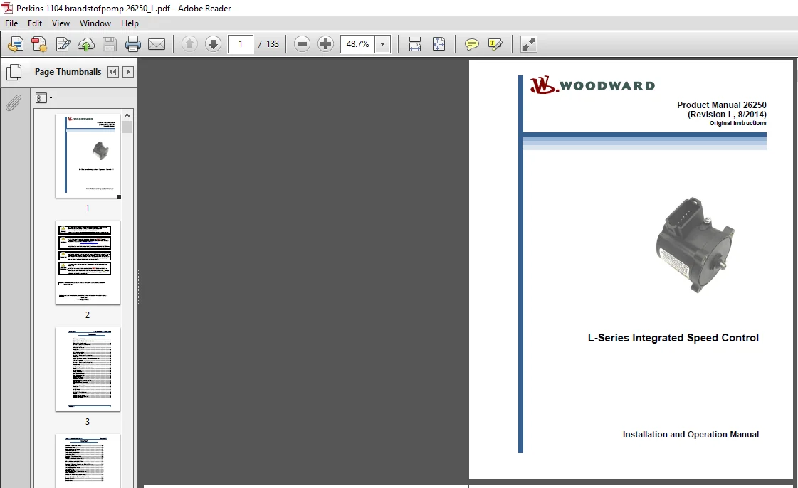
Woodward Product Manual 26250 L-Series Integrated Speed Control Installation & Op Manual
Original price was: $39.00.$19.95Current price is: $19.95.
Woodward Product Manual 26250 L-Series Integrated Speed Control Installation & Operation Manual – PDF Download
Description
Woodward Product Manual 26250 L-Series Integrated Speed Control Installation & Operation Manual – PDF Download
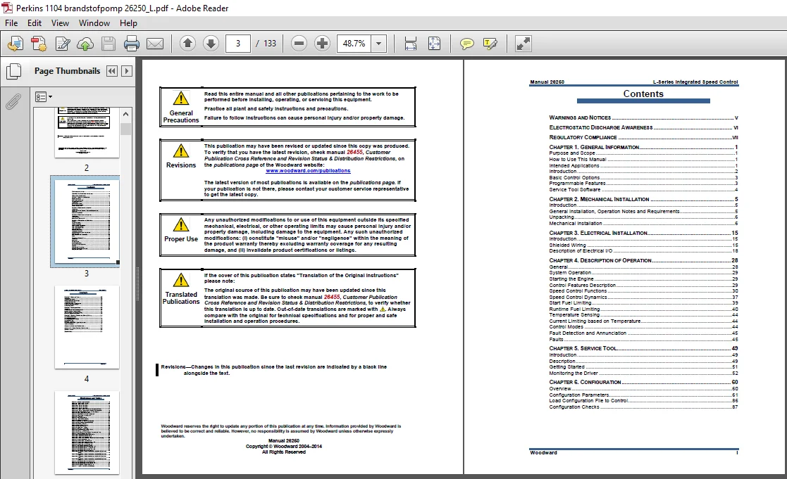
The Woodward Product Manual 26250 L-Series Integrated Speed Control Installation & Op Manual covers the following topics:
WARNINGS AND NOTICES …………………………………………………………………. V
ELECTROSTATIC DISCHARGE AWARENESS …………………………………………. VI
REGULATORY COMPLIANCE ……………………………………………………………..VII
CHAPTER 1. GENERAL INFORMATION ………………………………………………….. 1
Purpose and Scope …………………………………………………………………………………… 1
How to Use This Manual ……………………………………………………………………………. 1
Intended Applications ………………………………………………………………………………… 1
Introduction ………………………………………………………………………………………………. 2
Basic Control Options ………………………………………………………………………………… 3
Programmable Features …………………………………………………………………………….. 3
Service Tool Software ……………………………………………………………………………….. 4
CHAPTER 2. MECHANICAL INSTALLATION ……………………………………………. 5
Introduction ………………………………………………………………………………………………. 5
General Installation, Operation Notes and Requirements ……………………………….. 5
Unpacking ………………………………………………………………………………………………… 6
Mechanical Installation ………………………………………………………………………………. 6
CHAPTER 3. ELECTRICAL INSTALLATION ……………………………………………. 15
Introduction …………………………………………………………………………………………….. 15
Shielded Wiring ………………………………………………………………………………………. 15
Description of Electrical I/O ………………………………………………………………………. 18
CHAPTER 4. DESCRIPTION OF OPERATION …………………………………………. 28
General ………………………………………………………………………………………………….. 28
System Operation ……………………………………………………………………………………. 29
Starting the Engine ………………………………………………………………………………….. 29
Control Features Description …………………………………………………………………….. 29
Speed Control Functions ………………………………………………………………………….. 30
Speed Control Dynamics ………………………………………………………………………….. 37
Start Fuel Limiting……………………………………………………………………………………. 39
Runtime Fuel Limiting ………………………………………………………………………………. 40
Temperature Sensing ………………………………………………………………………………. 44
Current Limiting based on Temperature ……………………………………………………… 44
Control Modes ………………………………………………………………………………………… 44
Fault Detection and Annunciation ……………………………………………………………… 45
Faults …………………………………………………………………………………………………….. 45
CHAPTER 5. SERVICE TOOL…………………………………………………………….. 49
Introduction …………………………………………………………………………………………….. 49
Description ……………………………………………………………………………………………… 49
Getting Started ……………………………………………………………………………………….. 51
Monitoring the Driver ……………………………………………………………………………….. 52
CHAPTER 6. CONFIGURATION ………………………………………………………….. 60
Overview ………………………………………………………………………………………………… 60
Configuration Parameters …………………………………………………………………………. 61
Load Configuration File to Control ……………………………………………………………… 86
Configuration Checks ………………………………………………………………………………. 87
L-Series Integrated Speed Control Manual 26250
ii Woodward
Contents
CHAPTER 7. SETUP AND TUNING ………………………………………………………. 90
Introduction …………………………………………………………………………………………….. 90
Tuning the Speed PID ……………………………………………………………………………… 90
Editing of Configuration Settings ……………………………………………………………….. 91
Tuning the Position PID ……………………………………………………………………………. 93
Position Calibration and Verification …………………………………………………………… 95
Calibration Sequence Overview ………………………………………………………………… 95
Position Verification …………………………………………………………………………………. 96
CHAPTER 8. TROUBLESHOOTING ……………………………………………………. 100
Introduction ……………………………………………………………………………………………100
General System Troubleshooting Guide ……………………………………………………101
Engine/Generator Troubleshooting …………………………………………………………..101
Troubleshooting Diagnostic Fault Flags …………………………………………………….105
Electrical Troubleshooting Guide ………………………………………………………………109
CHAPTER 9. PRODUCT SUPPORT AND SERVICE OPTIONS ……………………. 111
Product Support Options …………………………………………………………………………111
Product Service Options ………………………………………………………………………….111
Returning Equipment for Repair ……………………………………………………………….112
Replacement Parts …………………………………………………………………………………112
Engineering Services ………………………………………………………………………………113
Contacting Woodward’s Support Organization …………………………………………..113
Technical Assistance ………………………………………………………………………………114
APPENDIX A. ACRONYMS/ABBREVIATIONS ……………………………………….. 115
APPENDIX B. L-SERIES CONTROL SPECIFICATIONS ……………………………. 116
REVISION HISTORY ………………………………………………………………………. 120
DECLARATIONS …………………………………………………………………………… 121
Manual 26250 L-Series Integrated Speed Control
Woodward iii
Illustrations and Tables
Figure 2-1. Linkage Design Examples …………………………………………………………. 8
Figure 2-2. L-Series Outline Drawing …………………………………………………………. 10
Figure 2-3. L-Series Cover Types ……………………………………………………………… 11
Figure 2-4a. L-Series Shaft Types …………………………………………………………….. 12
Figure 2-4b. L-Series Shaft Types …………………………………………………………….. 13
Figure 2-4c. L-Series Shaft Types ……………………………………………………………… 14
Figure 3-1a. Typical L-Series Speed Control Application Wiring ……………………. 17
Figure 3-1b. L-Series Speed Control Connector Pin Arrangement …………………. 18
Figure 3-2. Correct and Incorrect Wiring to Power Supply …………………………….. 19
Figure 3-3. MPU Speed Sensing Input ……………………………………………………….. 20
Figure 3-4. Proximity Probe Speed Sensing Input ……………………………………….. 21
Figure 3-5. Ignition Speed Sensing Input ……………………………………………………. 21
Figure 3-6. TPS Output ……………………………………………………………………………. 22
Figure 3-7. Relay Driver Output ………………………………………………………………… 23
Figure 3-8. Typical AUX Input Usage …………………………………………………………. 25
Figure 3-9. Ground Junction Point …………………………………………………………….. 27
Figure 4-1 Overview of L-Series Inputs/Outputs ………………………………………….. 30
Figure 4-2 Speed Setpoint Actions and Rates …………………………………………….. 31
Figure 4-3. 5% Droop Example …………………………………………………………………. 35
Figure 4-4 Remote Speed Setpoint ……………………………………………………………. 36
Figure 4-5. Dual Gain Settings ………………………………………………………………….. 38
Figure 4-6. Single Start Fuel Limit ……………………………………………………………… 39
Figure 4-7. Dual Start Fuel Limiters …………………………………………………………… 40
Figure 4-8. Boost (External) Fuel Limit Curve ……………………………………………… 41
Figure 4-9. Runtime Fuel Limit Curve ………………………………………………………… 42
Figure 4-10. Runtime Curve with Altitude Compensation Curve …………………….. 43
Figure 5-1. Example Service Tool Screen …………………………………………………… 49
Figure 5-2a. Programming Harness Connections ………………………………………… 50
Figure 5-2b. Programming Harness Wiring …………………………………………………. 51
Figure 5-3a. Service Tool—Overview Tab ………………………………………………….. 54
Figure 5-3b. Service Tool—Overview Tab (5418-2193 software only) ……………. 54
Figure 5-4. Service Tool—Alarms Tab ……………………………………………………….. 56
Figure 5-5. Service Tool—Shutdowns Tab …………………………………………………. 57
Figure 5-6. Service Tool—Internal Shutdowns Tab ……………………………………… 57
Figure 5-7. Service Tool—Simulated I/O Tab ……………………………………………… 58
Figure 5-8. Service Tool—Identification Tab ……………………………………………….. 59
Figure 6-1. Configuration Selection Options ……………………………………………….. 61
Figure 6-2. Configuration Editor—OVERVIEW TAB …………………………………….. 62
Figure 6-3. Configuration Editor—SETPOINT TAB ……………………………………… 64
Figure 6-4. Configuration Editor—CONTROL TAB ………………………………………. 66
Figure 6-5. Configuration Editor—Modifiers Tab ………………………………………….. 70
Figure 6-6a. Configuration Editor—Fuel Limiting Tab (5418-1680 software
version) ……………………………………………………………………………….. 72
Figure 6-6b. Configuration Editor—Fuel Limiting Tab (5418-6634 software
only) ……………………………………………………………………………………. 73
Figure 6-6c. Configuration Editor—Fuel Limiting Tab (5418-2193 software
only) ……………………………………………………………………………………. 73
Figure 6-6d. Configuration Editor—Fuel Limiting Tab (5418-2193 software
only) ……………………………………………………………………………………. 74
Figure 6-7. Configuration Editor—Dynamics Tab ………………………………………… 77
Figure 6-8. Configuration Editor—Discrete I/O Tab ……………………………………… 79
Figure 6-9. Configuration Editor—Alarm/Shutdown Tab ……………………………….. 82
Figure 6-10. Configuration Editor—Security Tab …………………………………………. 84
Figure 6-11. Security Tab Set Password Pop-up ………………………………………….
Figure 6-12. Password Entry Prompt …………………………………………………………. 85
Figure 6-13. Configuration Loading ……………………………………………………………. 86
Figure 6-14. Direct Load of Configuration File …………………………………………….. 86
Figure 7-1. Service Tool–Speed Dynamics …………………………………………………. 91
Figure 7-2a. Edit Configuration Settings Menu (5418-2193 software only) ……… 92
Figure 7-2b. Speed Input Window (5418-1680 software version) …………………… 92
Figure 7-2c. Configuration Settings Window (5418-2193 software only) …………. 93
Figure 7-3. Service Tool—PID Tuning Window ……………………………………………. 94
Figure 7-4. Service Tool—PID Tuning Properties Window ……………………………. 94
Figure 7-5. Service Tool—Manual Position Calibration selection …………………… 95
Figure 7-6. Service Tool—Verify Position Calibration …………………………………… 96
Figure 7-7. Service Tool—Manual Position Calibration…………………………………. 97
Figure 7-8. Service Tool—Manual Position Calibration Settings ……………………. 98
Figure 7-9. Service Tool—Auto Position Calibration …………………………………….. 99
Figure B-1. Bode Plot of L-Series Response ……………………………………………..119
WOODWARD PRODUCT MANUAL 26250 L-SERIES INTEGRATED SPEED CONTROL INSTALLATION & OP MANUAL:
IMAGE PREVIEW
PLEASE NOTE:
- This is the same manual used by the dealers to diagnose and troubleshoot your vehicle
- You will be directed to the download page as soon as the purchase is completed. The whole payment and downloading process will take anywhere between 2-5 minutes
- Need any other service / repair / parts manual, please feel free to contact [email protected] . We still have 50,000 manuals unlisted