Yale С839 ERC 35-55 HG Service Manual – PDF DOWNLOAD
Original price was: $87.95.$26.95Current price is: $26.95.
Yale С839 ERC 35-55 HG Service Manual – PDF DOWNLOAD
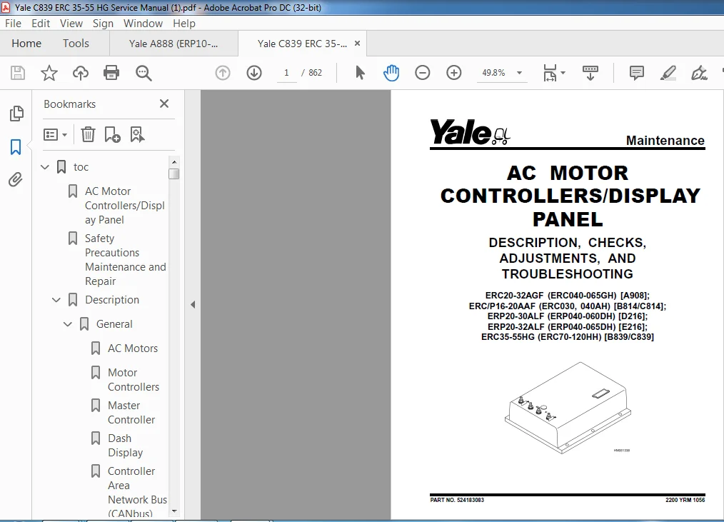
ERC20-32AGF (ERC040-065GH) [A908];
ERC/P16-20AAF (ERC030, 040AH) [B814/C814];
ERP20-30ALF (ERP040-060DH) [D216];
ERP20-32ALF (ERP040-065DH) [E216];
ERC35-55HG (ERC70-120HH) [B839/C839]
Description
Yale С839 ERC 35-55 HG Service Manual – PDF DOWNLOAD
FILE DETAILS:
Yale С839 ERC 35-55 HG Service Manual – PDF DOWNLOAD
Format: PDF
Language: English
Brand: Yale
DESCRIPTION:
Yale С839 ERC 35-55 HG Service Manual – PDF DOWNLOAD
ERC20-32AGF (ERC040-065GH) [A908];
ERC/P16-20AAF (ERC030, 040AH) [B814/C814];
ERP20-30ALF (ERP040-060DH) [D216];
ERP20-32ALF (ERP040-065DH) [E216];
ERC35-55HG (ERC70-120HH) [B839/C839]
SAFETY PRECAUTIONS MAINTENANCE AND REPAIR:
• When lifting parts or assemblies, make sure all slings, chains, or cables are correctly fastened, and that the load being lifted is balanced. Make sure the crane, cables, and chains have the capacity to support the weight of the load.
• Do not lift heavy parts by hand, use a lifting mechanism.
• Wear safety glasses.
• DISCONNECT THE BATTERY CONNECTOR before doing any maintenance or repair on electric lift trucks. Disconnect the battery ground cable on internal combustion lift trucks.
• Always use correct blocks to prevent the unit from rolling or falling. See HOW TO PUT THE LIFT TRUCK ON BLOCKS in the Operating Manual or the Periodic Maintenance section.
• Keep the unit clean and the working area clean and orderly.
• Use the correct tools for the job.
• Keep the tools clean and in good condition.
• Always use YALE APPROVED parts when making repairs. Replacement parts must meet or exceed the specifications of the original equipment manufacturer.
• Make sure all nuts, bolts, snap rings, and other fastening devices are removed before using force to remove parts.
• Always fasten a DO NOT OPERATE tag to the controls of the unit when making repairs, or if the unit needs repairs.
• Be sure to follow the WARNING and CAUTION notes in the instructions.
• Gasoline, Liquid Petroleum Gas (LPG), Compressed Natural Gas (CNG), and Diesel fuel are flammable. Be sure to follow the necessary safety precautions when handling these fuels and when working on these fuel systems.
• Batteries generate flammable gas when they are being charged. Keep fire and sparks away from the area. Make sure the area is well ventilated.
GENERAL:
The alternating current (AC) system consists of AC motors, motor controller(s), a master controller, and a dash display. The major difference between the AC system and the direct current (DC) system is the master controller performs many of the same functions that previously were performed in the motor controllers on the DC system.
AC Motors :
The AC motors are three-phase AC induction motors. They do not include motor brushes or commutators. An AC induction motor operates on three-phase AC power provided directly by the motor controller. The motor’s speed is controlled by the motor controller and can be changed by changing the frequency of the AC power provided to the motor. A speed sensor is built into the rear motor bearing, which provides RPM and direction feedback to the motor controller. The motor controller continuously monitors motor direction and speed. Using this feedback, the AC motor control system can provide much better vehicle top speed control than is available with DC SEM systems. The AC motors also have thermal sensors embedded in the motor windings that are continuously monitored by the motor controllers.
YALE С839 ERC 35-55 HG SERVICE MANUAL – PDF DOWNLOAD:
TABLE OF CONTENTS:
Yale С839 ERC 35-55 HG Service Manual – PDF DOWNLOAD
toc 1
AC Motor Controllers/Display Panel 1
Safety Precautions Maintenance and Repair 2
Description 5
General 5
AC Motors 5
Motor Controllers 5
Master Controller 5
Dash Display 5
Controller Area Network Bus (CANbus) 5
Master Controller Checks and Adjustments 6
Function Settings 7
General 7
Function Numbers 7
Function Descriptions 10
General 10
Function Number 1 BATTERY VOLTAGE 10
Function Number 2 EXTENDED SHIFT 10
Function Number 3 ACCELERATION 1 10
Function Number 4 ACCELERATION 2 10
Function Number 5 TOP SPEED LIMIT 10
Function Number 6 REGEN BRAKING 10
Function Number 7 AUTO DECELERATION 11
Function Number 8 BDI ADJUSTMENT 11
Function Number 9 LIFT INTERRUPT 11
Function Number 10 POWER STEERING TIME DELAY 11
Function Number 11 SERVICE REMINDER 11
Function Number 12 CUSTOM 11
Function Number 13 PUMP SPEED 1 11
Function Number 14 PUMP SPEED 2 12
Function Number 15 PUMP SPEED 3 12
Function Number 16 PUMP ACCELERATION 12
Troubleshooting 12
General 12
Controller Status Light Emitting Diodes (LEDs) 13
Master Controller 13
AC Motor Controllers 13
Status Codes 19
AC Motor Controllers Status Code Charts 21
Troubleshooting When Dash and/or Lift Truck is not Operational 42
Typical Symptoms 42
Truck Runs but Dash Display is not Operational, or Only Displays 42
Truck Does Not Run and Dash is Not Operational or Only Displays 43
Hydraulics Operate Normally, Traction Does Not Operate Correctly 44
Traction Operates Normally, Hydraulics do Not Operate Correctly, 44
AC Transistor Motor Controller Replacement 44
General 44
General Maintenance Instructions 50
Special Precautions 50
Fuses 51
Fan Test 51
Contactors 51
Repair 51
Thermal Sensors 55
Motor Controller, Replace 55
Display Panel 56
General 56
Premium Display Panel 56
Standard Display Panel 56
Display Functions and Features 57
Key-On Initialization 57
Standard Display 58
Premium Display 58
Lift Truck Inspection Function 59
Access to Service Functions 59
Service Functions 59
Service Functions 60
Performance Modes 62
Battery Discharge Indicator (BDI) 62
Hourmeter 63
Dash Display Service Menu Navigation 69
General 69
Moving Through Menu Selections 69
Editing and Adding Information 69
tables 1
Table 1 Factory Parameters for ERP20-30ALF (ERP040-060DH) (D216 7
Table 2 Factory Setting for ERC020-032AGF (ERC40-65GH) (A908) 8
Table 3 Factory Setting for ERC/P16-20AAF (ERC030-040AH) (B814/ 8
Table 4 Factory Parameters for ERC35-55HG (ERC70-120HH) (B839/C 9
Table 5 List of Status Codes 19
Table 6 42-Pin Connections/Descriptions for Master Controller 52
Table 7 Pin Connections/Descriptions for 72/80 (Gen IV) Volt Mo 54
Table 8 Pin Connections/Descriptions for 36/48 and 72v/80v (Gen 54
toc 73
AC Motor Repair 73
Safety Precautions Maintenance and Repair 74
General 77
AC Motor Repair 77
Disassemble 77
Assemble 81
Troubleshooting 83
toc 87
Brake System 87
Safety Precautions Maintenance and Repair 88
General 91
Description and Operation 91
Brake Booster and Master Cylinder 91
Master Cylinder 91
Service Brake Assembly 91
Parking Brake 95
Seat Brake 96
Brake Shoe Assemblies Repair 97
Remove and Disassemble 97
Clean and Inspect 97
Assemble and Install 99
Master Cylinder Repair 103
Master Cylinder For Lift Truck Models GC/GLC70-120LG/MG (B818) a 103
Remove 103
Disassemble 103
Assemble 104
Install 104
Master Cylinder For Lift Truck Models ERC70-120HD, ERC70-120HG ( 105
Remove and Disassemble 105
Clean and Inspect 106
Assemble and Install 106
Brake Booster Repair 106
Remove 106
Disassemble 106
Clean and Inspect 107
Assemble 108
Install 108
Brake System Air Removal 108
Brake Pedal Adjustment 108
Brake Pedal GP/GLP/GDP70-120LG/MG (B813) With Manual Transmissio 108
Brake Shoes Adjustment 110
Parking Brake Adjustment 110
Parking Brake Adjustment, Lift Truck Models GC/GLC70-120LG/MG (B 110
Parking Brake Lever and Switch Adjustment ERC70-120HD and ERC70- 111
Seat Brake Assembly 112
Remove 112
Clean and Inspect 112
Install 112
Adjustments 114
Solenoid Adjustment 114
Traction cutoff Switch Adjustment 114
Cable Adjustment 114
Brake Booster Relief Valve Check 117
Troubleshooting 117
toc 123
Capacities and Specifications 123
Safety Precautions Maintenance and Repair 124
Lift Truck Lifting Capacity 127
Counterweight Weights 127
Tire Sizes 127
Capacities 128
Hydraulic System 128
Steering System 129
Specifications 129
Turning Radius 129
Mast Speeds 130
Maximum Carriage and Tilt Creep Rates 131
Battery Specifications 131
Traction Motor Speed 132
Battery Current at Hoist Relief 132
Torque Specifications 132
Brake System 132
Differential 133
Drive Axle 133
Frame 133
Mast 133
Main Control Valve 133
Steering System 133
Tilt Cylinders 134
Hydraulic System 134
Electrical System 134
tables 123
Table 1 Manual Control Valve 128
Table 2 E-Hydraulic Control Valve 128
toc 137
Cylinder Repair 137
Safety Precautions Maintenance and Repair 138
General 141
Description 141
Safety Procedures When Working Near Mast 142
Tilt Cylinder Repair 144
Remove 144
Disassemble 145
Inspect 145
Clean 145
Assemble 148
Install 149
Tilt Cylinders, Adjust 150
Tilt Cylinder Leak Check 152
Torque Specifications 153
Piston Rod Nut 153
Gland 153
Tilt Cylinder Mounting Capscrew 153
Tilt Cylinder Rod End Nut 153
Lift Cylinder Repair 154
Main Lift Cylinders 154
Remove 154
Disassemble 155
Clean 156
Inspect 156
Assemble 156
Install 156
System Air Bleed Procedures 157
Two-Stage FFL Left Side Main Lift Cylinder 158
Disassemble 158
Clean 160
Inspect 160
Assemble 160
Install 160
Free-Lift Cylinder 161
Remove 161
Disassemble 164
Clean 164
Inspect 165
Assemble 165
Install 166
Torque Specifications 166
Lift Cylinders Leak Check 167
tables 137
Table 1 Movement Rates (Maximum) for Tilt Cylinders 152
toc 171
Diagrams 171
Safety Precautions Maintenance and Repair 172
toc 211
Drive Axle, Speed Reducer, and Differential 211
Safety Precautions Maintenance and Repair 212
General 215
Description 215
Drive Axle, Speed Reducer, and Differential Repair 216
Remove 216
General 216
Traction Motor, Speed Reducer, and Differential 217
Motor, Speed Reducer, and Differential, Remove 217
Disassemble 220
Speed Reducer 220
Differential 221
Clean 222
Inspect 222
Assemble 222
Speed Reducer 222
Input Gear, Install 222
New Pinion, Install 222
Differential 225
Drive Axle Housing 228
Remove 228
Clean 229
Inspect 229
Assemble 229
Troubleshooting 232
tables 211
Table 1 Pinion Assembly Shims Adjustment 224
Table 2 Ring and Pinion Tooth Contact Adjustment 226
toc 235
Electrical System (Trucks With AC Controllers) 235
Safety Precautions Maintenance and Repair 236
General 239
Description 240
Features of the Display Panels 240
Other Control Components 241
Display Panel and Key Switch Replacement 242
Display Panel, Replace 242
Key Switch, Replace 244
Controller Replacement 244
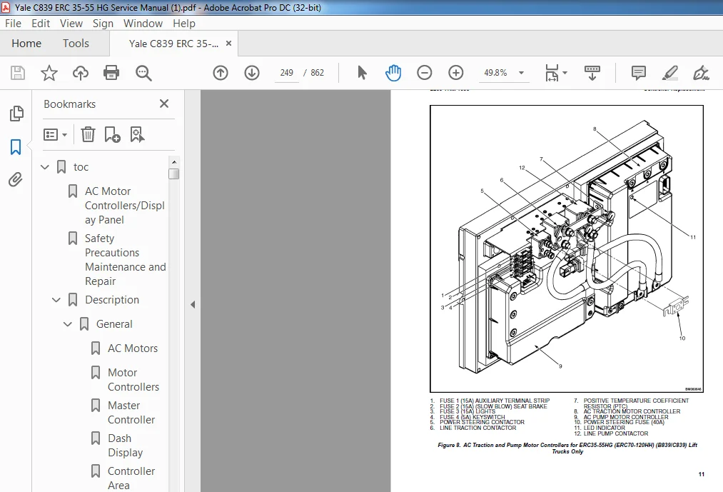
Traction and Pump Motor Controller Replacement 244
Master Controller, Replace 250
Master Controller, Remove ERP20-30ALF (ERP040-060DH) (D216), ERP 250
Master Controller, Install ERP20-30ALF (ERP040-060DH) (D216), ER 250
Master Controller, Remove ERC/P16-20AAF (ERC030-040AH) (B814/C81 252
Master Controller, Install ERC/P16-20AAF (ERC030-040AH) (B814/C8 252
Master Controller, Remove ERC35-55HG (ERC070-120HH) (B839/C839) 254
Master Controller, Install ERC35-55HG (ERC070-120HH) (B839/C839) 254
Control Components Replacement 255
General 255
Start Switch, Replace 255
Brake Light Switch, Replace 256
Seat Switch, Replace 256
Parking Brake Switch, Replace 257
Foot Directional Control Pedal Direction Switches, Replace 259
Steering Column Direction Control Switches, Replace 262
Remove 262
Install 262
Brake Fluid Switch, Replace 264
Brush Wear and Over Temperature Sensors (DC Pump Motor Only) 264
Rocker Switches for Lights, Replace 264
Accelerator Position Sensor, Replace 265
On-Demand Steering Sensor, Replace 266
Lights, Converter, Relay, and Reverse Alarm 266
Brake, Tail, and Reverse Light Assembly, Replace 267
Incandescent Assembly 267
LED Assembly – Remove 269
LED Assembly – Install 269
Strobe Light Assembly, Replace 272
Wire Harness Repair 273
Del-City Crimp-Solder-Shrink Splice 273
Front, Rear Driving Light or Spot Light Assemblies, Replace 274
Converter, Replace 274
Remove, Lift Truck Models ERP20-30ALF (ERP040-060DH) (D216), ERP 274
Install, Lift Truck Models ERP20-30ALF (ERP040-060DH) (D216), ER 276
Remove, Lift Truck Models ERC20-32AGF (ERC040-065GH) (A908) and 276
Install, Lift Truck Models ERC20-32AGF (ERC040-065GH) (A908) and 276
Remove, Lift Truck Models ERC35-55HG (ERC70-120HH) (B839/C839) 278
Install, Lift Truck Models ERC35-55HG (ERC70-120HH) (B839/C839) 278
Reverse Relay, Replace 279
Lift Truck Models ERC20-32AGF (ERC040-065GH) (A908), ERC/P16-20A 279
Lift Truck Models ERC35-55HG (ERC70-120HH) (B839/C839) 279
Backup Alarm, Replace 281
Horn and Horn Button, Replace 281
Horn Replacement for Lift Trucks ERP20-30ALF (ERP040-060DH) (D21 281
Horn Replacement for Lift Trucks ERC35-55HG (ERC70-120HH) (B839/ 283
Horn Switch and Cover, Replace 284
Hydraulic Pump Switches 285
Fan Power Supply, Replace 285
Remove, Lift Truck Models ERC35-55HG (ERC70-120HH) (B839/C839) 285
Install, Lift Truck Models ERC35-55HG (ERC70-120HH) (B839/C839) 285
Remove, Lift Truck Models ERP20-30ALF (ERP040-060DH) (D216) and 286
Install, Lift Truck Models ERP20-30ALF (ERP040-060DH) (D216) and 287
Remove, Lift Truck Models ERC20-32AGF (ERC040-065GH) (A908) 287
Install, Lift Truck Models ERC20-32AGF (ERC040-065GH) (A908) 287
Control and Power Fuse Check 288
Fuse Locations 288
Brake Light Switch Adjustment 294
Seat Switch Check 295
Seat Brake Adjustment 295
Parking Brake Switch Adjustment 296
Direction Switches Check 296
Foot Directional Control Pedal 296
Steering Column 297
Foot Directional Control Pedal or Accelerator Pedal Adjustment 297
Accelerator Position Sensor Adjustment and Start Switch Adjustme 298
Acceleration Position Sensor, Adjust 298
Start Switch, Adjust 300
tables 235
Table 1 Wire Splice Size 273
toc 303
Frame 303
Safety Precautions Maintenance and Repair 304
General 307
Description 307
Overhead Guard Replacement 309
Remove 309
Install 310
Battery and Operator Restraint, Hood and Seat Brake Repair 311
Battery Restraint and Hood Repair 311
Operator Restraint System and Seat Assembly 314
Automatic Locking Retractor (ALR) 314
Emergency Locking Retractor (ELR) 314
Seat Brake Repair 315
Counterweight Replacement 315
Remove 315
Install 316
Traction Motor Repair 316
Remove 316
Install 317
Hydraulic Tank Repair 318
Inspect 318
Small Leaks, Repair 318
Large Leaks, Repair 318
Clean 318
Steam Method 319
Chemical Solution Method 319
Additional Preparations For Repair 319
Safety Label Replacement 320
Battery Specifications 322
tables 303
Table 1 Torque Values 310
Table 2 Weight of Counterweights 315
Table 3 Battery Specifications* 322
toc 325
Hydraulic System 325
Safety Precautions Maintenance and Repair 326
General 329
Description 329
Hydraulic System 329
Operation 337
Hydraulic System 337
Hydraulic Gear Pump 343
Steering Pump 343
Hydraulic Tank Repair 351
Tank, Remove [ERC/P16-20AAF (ERC030-040AF, AG/BG) (A814); ERC/P1 351
Tank, Remove [ERP20-30ALF (B216) and ERP20-30ALF (ERP040-060DH) 353
Tank, Remove [ERP20-32ALF (ERP040-065DH) (E216)] 354
Hydraulic Tank [ERC35-55HG (ERC70-120HH) (B839/C839)] 354
Inspect 355
Small Leaks, Repair 356
Large Leaks, Repair 356
Clean 356
Steam Method 356
Chemical Solution Method 357
Additional Methods for Tank Repair 357
Tank, Install [ERC/P16-20AAF (ERC030-040AF, AG/BG) (A814); ERC/P 357
Tank, Install [ERP20-30ALF (B216) and ERP20-30ALF (ERP040-060DH) 358
Tank, Install [ERP20-32ALF (ERP040-065DH) (E216)] 358
Filter Replacement 359
All Lift Trucks Except [ERC35-55HG (ERC70-120HH) (B839/C839); ER 359
Remove 359
Install 360
Lift Truck Models [ERC35-55HG (ERC70-120HH) (B839/C839)] 360
Remove 360
Install 360
Lift truck Models [ERC20-32AGF (ERC040-065GH) (A908) and ERC/P16 361
Remove 361
Install 361
Lift Truck Models [ERP20-32ALF (ERP040-065DH) (E216)] 363
Remove 363
Install 363
Hydraulic Pump Repair 366
Hydraulic Pump, Remove [ERC/P16-20AAF (ERC030-040AF, AG/BG) (A81 366
Hydraulic Pump, Disassemble ERC/P16-20AAF (ERC030-040AF, AG/BG) 366
Inspect 368
Clean 368
Pump Seal Replace and Pump Assemble 368
Assemble Pump on Motor 368
Hydraulic Pump and Motor, Install [ERC/P16-20AAF (ERC030-040AF, 370
Hydraulic Pump, Remove [ERP20-30ALF (B216); ERP20-30ALF (ERP040- 371
Hydraulic Pump, Disassemble [ERC35-55HG (ERC70-120HH) (B839/C839 372
Hydraulic Pump, Inspect [ERC35-55HG (ERC70-120HH) (B839/C839) an 374
Hydraulic Pump, Clean [ERC35-55HG (ERC70-120HH) (B839/C839) and 374
Hydraulic Pump, Assemble [ERC35-55HG (ERC70-120HH) (B839/C839) a 374
Hydraulic Pump and Motor, Install [ERP20-30ALF (B216); ERP20-30A 374
Main Control Valve Repair 376
Steering Pump Repair 376
Pump, Remove and Disassemble [ERC/P16-20AAF (ERC030-040AF, ERC03 376
Pump, Remove and Disassemble [ERP20-30ALF (B216); ERP20-30ALF (E 378
Pump, Assemble and Install 380
Steering Control Unit Replacement 381
Remove 381
Install 381
Steering Cylinder Repair 387
Main Control Valve Check and Adjust 387
Steering Relief Valve Check and Adjust 388
Specifications 388
Relief Valve Pressures* 388
Hydraulic Tank Capacity (dipstick full mark) 389
Hydraulic Pump Capacities – All Models Except ERC35-55HG (ERC70- 389
Hydraulic Pump Capacities – Models ERC35-55HG (ERC70-120HH) (B83 389
Troubleshooting 389
Steering 389
Steering Housing and Steering Control Unit 390
Hydraulic System 391
toc 397
Industrial Battery 397
Safety Precautions Maintenance and Repair 398
General 401
Lead-Acid Batteries 401
Specific Gravity 402
Chemical Reaction in a Cell 402
Electrical Terms 403
Battery Selection 404
Battery Voltage 405
Battery as a Counterweight 405
Battery Ratings 406
Kilowatt-Hours 406
Battery Maintenance 406
Safety Procedures 406
Maintenance Records 407
New Battery 407
Cleaning Battery 407
Adding Water to Battery 409
Hydrometer 410
Battery Temperature 410
Charging Battery 411
Types of Battery Charges 412
Methods of Charging 413
Troubleshooting Charger 414
Knowing When Battery Is Fully Charged 414
Where to Charge Batteries 414
Equipment Needed 414
Battery Connectors 415
Battery Care 415
tables 397
Table 1 Battery Capacity Terms 406
toc 419
Electro-hydraulic Control Valve 419
Safety Precautions Maintenance and Repair 420
General 423
Description 423
Electro-Hydraulic Control System 423
Electro-Hydraulic Control Valve 426
Electro-Hydraulic Valve Driver Module 442
Mini-Lever Module (MLM) 442
Joystick 443
Electro-Hydraulic Control Valve Repair 444
Remove 444
Disassemble 453
Solenoid Coil Replacement 455
Cartridge Replacement 457
Electro-Hydraulic Pressure Reducing Valve (EHPR) Replacement 458
Lift Circuit Check Valve Replacement 459
Compensator Cartridge Replacement 459
Primary and Secondary Relief Valves Replacement 459
Tilt Counterbalance Valve Replacement 460
Flow Regulator Valve Replacement 460
Assemble 460
Install 460
E-Hydraulics Calibration 469
Mini-Lever Module 471
Mini-Lever Module (MLM) 471
Remove 471
Install 471
Mini-Lever Replacement 471
Remove 471
Clean and Inspect 472
Install 472
Push Button Switch Replacement 473
Remove 473
Install 474
Test 475
Mini-levers 475
Full Stroke Test 475
Function Returns to Neutral Test 475
Push Button Switch 476
Joystick 476
Remove and Disassemble 476
Inspect 476
Assemble and Install 476
Troubleshooting 477
tables 419
Table 1 Primary and Secondary Relief Valve Values 429
Table 2 Solenoid Resistance Values 455
Table 3 Cartridge and Solenoid Coil Nut Torque for Lift truck M 458
Table 4 Cartridge and Solenoid Coil Nut Torque for Lift truck M 458
toc 489
Manual hydraulic Control Valve 489
Safety Precautions Maintenance and Repair 490
General 493
Description 493
Operation 495
Lift Section 497
Tilt Section 498
Tilt Backward 498
Tilt Forward 498
Relief Valve 500
Solenoid Valve for Auxiliary Function 501
Main Control Valve Repair 502
Remove and Disassemble – Control Valve Without OPS Solenoid 502
Remove and Disassemble – Control Valve With OPS Solenoid 502
Clean and Inspect 504
Assemble – Control Valve Without OPS 504
Assemble – Control Valve With OPS 504
Install 505
Solenoid Valve for Auxiliary Function Repair 505
Remove and Disassemble 505
Assemble and Install 507
Troubleshooting 507
Pressure Relief Valve Check and Adjustment 508
Primary Relief Valve 508
Secondary Relief Valve 508
Control Lever Arrangement and Adjustment 509
Specifications 511
Troubleshooting 511
toc 517
Mast Repairs 517
Safety Precautions Maintenance and Repair 518
Safety Procedures When Working Near Mast 521
Fork Replacement 523
Remove 523
Install 524
Checks 524
Carriage Replacement 525
Remove 525
Install 531
Disconnecting Attachment Hydraulic Quick Disconnect Hoses 532
Connecting Attachment Hydraulic Quick Disconnect Hoses 533
Integral Sideshift Carriage Repair 533
Remove, for lift truck models ERC35-55HG (ERC70-120HH) (C839), G 533
Disassemble 534
Assemble 536
Install, for lift truck models ERC35-55HG (ERC70-120HH) (C839), 536
Hang On Sideshift Carriage Repair 536
Remove, Lift Truck Models GLP/GDP60VX, GLP/GDP70VX (GP/GLP/GDP13 536
Disassemble 542
Clean and Inspect 544
Assemble 544
Install 545
Two-Stage Mast With Limited Free-Lift Repair 546
Remove 546
Disassemble 548
Clean and Inspect 550
Assemble 559
Install, GLP/GDP40VX5/VX6; GLP/GDP45SVX5, GLP/GDP45VX6; GLP/GDP5 560
Install, GLC40, 45, 55VX; GLC55SVX; (GC/GLC080, 100, 120VX; GC/G 561
Header Hose Alignment 571
Two-Stage Mast With Full Free-Lift Repair 582
Remove 582
Disassemble 583
Clean and Inspect 589
Assemble 590
Install, GLP/GDP40VX5/VX6; GLP/GDP45SVX5, GLP/GDP45VX6; GLP/GDP5 592
Install, GLC40, 45, 55VX; GLC55SVX; (GC/GLC080, 100, 120VX; GC/G 594
Header Hose Installation and Adjustment 597
Installation 597
Adjustment 597
Three-Stage Mast With Full Free-Lift Repair 598
Remove 598
Disassemble 599
Clean and Inspect 611
Assemble 612
Install, GLP/GDP40VX5/VX6; GLP/GDP45SVX5, GLP/GDP45VX6; GLP/GDP5 614
Install, GLC40, 45, 55VX; GLC55SVX; (GC/GLC080, 100, 120VX; GC/G 618
Header Hose Alignment for GLC40, 45, 55VX; GLC55SVX; (GC/GLC080, 623
Header Hose Alignment for GLP/GDP60VX, GLP/GDP70VX (GP/GLP/GDP13 629
Mast Operation Check 633
Tilt Cylinder Adjustment 633
Lift Chains Adjustment 634
Mast Adjustments 635
Load Roller Adjustment 635
Mast Side Kicking Adjustment 637
Carriage Adjustments 638
tables 517
Table 1 Fork Tip Alignment 524
Table 2 Standard Mast Height; Header Hose Tension Mark Location 579
Table 3 Standard Mast Height; Header Hose Tension Mark Location 579
Table 4 Standard Mast Height; Header Hose Tension Mark Location 580
Table 5 Standard Mast Height; Header Hose Tension Mark Location 580
Table 6 Standard Mast Height; Header Hose Tension Mark Location 581
Table 7 Standard Mast Height; Header Hose Tension Mark Location 626
Table 8 Standard Mast Height; Header Hose Tension Mark Location 628
Table 9 Standard Mast Height; Header Hose Tension Mark Location 628
Table 10 Hook-Type Carriage Chain Adjustment 634
toc 641
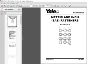
Metric and Inch (SAE) Fasteners 641
Safety Precautions Maintenance and Repair 642
General 645
Threaded Fasteners 645
Nomenclature, Threads 645
Strength Identification 646
Cotter (Split) Pins 646
Fastener Torque Tables 651
Conversion Table 653
tables 641
Table 1 Bolts and Screws 647
Table 2 Studs and Nuts 648
Table 3 Torque Nuts 649
Table 4 Torque Nuts with Nylon Insert 650
Table 5 Torque Values for Metric Fasteners* 651
Table 6 Torque Values for Inch Fasteners* 652
Table 7 Conversion Table for Metric and English Units 653
Table 8 Cotter Pin Dimensional Data 654
Table 9 Cotter Pin Dimensional Data 655
Table 10 Cotter Pin Dimensional Data 656
Table 11 Cotter Pin Dimensional Data 658
toc 661
Periodic Maintenance 661
Safety Precautions Maintenance and Repair 662
General 667
How to Move Disabled Lift Truck 667
How to Tow Lift Truck 667
How to Put Lift Trucks on Blocks 668
How to Raise Drive Tires 668
How to Raise Steering Tires 668
How to Clean a Lift Truck 669
Maintenance Schedule 670
Maintenance Procedures Every 8 Hours or Daily 674
General 674
How to Make Checks With Key Switch OFF 675
Tires and Wheels 675
Forks 675
Remove 675
Inspect 675
Install 676
Adjust 676
Inspection of Mast, Mast Pivots, Header Hoses and Lift Chains 677
Safety Labels 677
Steering Column Latch 677
Operator Restraint System 678
Automatic Locking Retractor (ALR) 678
Emergency Locking Retractor (ELR) 678
Battery Restraint System 679
Battery 680
Hydraulic System 681
How to Make Checks With Key Switch ON 682
Horn, Lights, and Alarm 682
Steering System 683
Service Brakes 683
Parking Brake 683
Seat Brake 683
Control Levers and Pedals 683
Direction and Speed Control Pedals 683
Lift System Operation 683
Oil Leaks 684
First Service After First 100 Hours of Operation 684
Change Hydraulic Oil and Filter 684
Lift Truck Models ERC35-55HG (ERC70-120HH) (C839) 684
Remove 684
Install 686
Lift Truck Models ERC35-55HG (ERC70-120HH) (B839) 687
Remove 687
Install 688
Maintenance Procedures Every 500 Hours or 3 Months 689
Wheel Nuts 689
Header Hose Checks 689
Mast Lubrication 689
Integral Sideshift Carriage 692
Brake Fluid 693
Other Lubrication 693
Maintenance Procedures Every 1000 Hours or 6 Months 693
Differential and Speed Reducer 693
Lift Chains 693
Wear Check 693
Lubrication 694
Forks 694
Parking Brake 694
Brake Linkage Shafts 695
Steering Spindles and Tie Rod Ends 695
Seat Rails 695
Seat Plate Hinges 695
Electrical Inspection 696
Contactors 696
Maintenance Procedures Every 2000 Hours or Yearly 698
Brake Fluid 698
Hydraulic System 699
Hydraulic Tank Breather, Lift Truck Models ERC35-55HG (ERC70-120 699
Change Hydraulic Oil and Hydraulic Oil Filter, Lift Truck Models 699
Remove 699
Install 700
Hydraulic Tank Breather, Lift Truck Models ERC35-55HG (ERC70-120 701
Remove 701
Install 701
Change Hydraulic Oil and Hydraulic Oil Filter, Lift Truck Models 701
Remove 701
Install 703
Differential and Speed Reducer 703
Service Brakes 704
Wheel Bearings 704
Steer Wheels, Lubrication 704
Drive Wheels, Lubrication 704
Lift Chains 704
Battery Maintenance 705
How to Charge Battery 705
How to Change Battery 706
Safety Procedures When Working Near Mast 709
Lift and Tilt System Leak Check 712
Check Lift Cylinders for Leaks 712
Check Tilt Cylinders for Leaks 712
Lift Chain Adjustments 713
Welding Repairs 714
Overhead Guard Changes 715
Wheels and Tires 715
General 715
Remove Wheels From Lift Truck 715
Remove Tire From Wheel and Install Tire on Wheel 715
Remove 715
Install 715
Install Wheels 716
tables 661
Table 1 Maintenance Schedule 671
Table 2 Battery Specifications* 709
Table 3 Hook-Type Carriage Chain Adjustment 714
toc 719
Steering Axle 719
Safety Precautions Maintenance and Repair 720
General 723
Description 723
Steering Axle Assembly Repair 728
Steering Axle GP/GLP/GDP070-110LG/MG (B813), GC/GLC070-120LG/MG 728
Remove 728
Install 728
Steering Axle GDP60-70CA (GP/GLP/GDP135-155CA) (A878, B878), GLP 729
Remove 729
Install 729
Wheels and Hubs Repair (All Units) 730
Remove and Disassemble 730
Clean 730
Inspect 730
Assemble and Install 730
Spindles and Bearings Repair (All Units) 732
Remove 732
Clean 732
Assemble and Install 733
Tie Rods Repair (All Units) 734
Remove 734
Clean 734
Install 734
Steering Cylinder Repair 737
Remove and Disassemble 737
Clean and Inspect 737
Assemble and Install 737
Troubleshooting 738
toc 743
Steering Housing and Control Unit 743
Safety Precautions Maintenance and Repair 744
General 747
Description 747
Operation 748
Steering Wheel and Column Assembly Repair 749
Assembly Components, Remove 749
Steering Control Unit, Disassemble 754
Steering Control Unit, Clean 754
Steering Control Unit, Assemble 754
Assembly Components, Install 756
System Air Removal 758
Troubleshooting 758
toc 763
Steering System for AC Electric Lift Trucks 763
Safety Precautions Maintenance and Repair 764
General 767
Description 768
Steering Wheel and Column Assembly Repair 769
General 769
Assembly Components, Remove 771
Assembly Components, Install 772
Power Steering Motor and Pump 773
Description 773
Remove 773
Disassemble 776
Install 776
Power Steering Pump, Repair 776
Seal, Replace 777
Steering System Air Removal 778
Steering Pressure Check 778
Steering Motor Circuits Check 779
Troubleshooting 780
toc 785
Troubleshooting and Adjustments Using the AC Controls Program (E 785
Safety Precautions Maintenance and Repair 786
General 789
Computer Requirements 789
Software, Install 789
Language Selection 789
Demo Mode 790
Connect PC to Lift Truck 794
Starting AC Controls Program 796
Lift Truck Control Setup 801
Change Lift Truck Serial Number or Hourmeter 801
Setting Factory Default Values or Changing Lift Truck Parameters 802
Create New Custom Lift Truck Configuration 808
Lift Truck Configuration Properties 811
Import New Lift Truck Configuration From Disk 814
Delete Custom Lift Truck Configuration or Password File 816
Dash Display 819
Custom Display Languages 819
Download Display Language 821
Clear Operator Log 821
Password Functions 824
Enable/Disable Password and Lift Truck Inspection Functions 824
Truck Inspection Checklist 824
Password 824
Password Properties 824
Create New Password File 829
Download Passwords 830
Upload Passwords 832
Reports Menu 834
Devices Report 834
Custom Report 834
Password Report 834
Operator Report 841
Current Settings Report 844
Status Code Report 848
Status Codes Log 851
Troubleshooting 853
Diagnostics 853
Help Menu 856
General 856
Contents 856
Technical Support 856
About Electric Truck AC Controls Program 856
IMAGES PREVIEW OF THE MANUAL:
PLEASE NOTE:
- This is the SAME manual used by the dealers to troubleshoot any faults in your vehicle. This can be yours in 2 minutes after the payment is made.
- Contact us at [email protected] should you have any queries before your purchase or that you need any other service / repair / parts operators manual.