Yale Forklift A284 (MPR080VG, MPR100VG) Service Manual – PDF DOWNLOAD
$35.95
Yale Forklift A284 (MPR080VG, MPR100VG) Service Manual – PDF DOWNLOAD
Description
Yale Forklift A284 (MPR080VG, MPR100VG) Service Manual – PDF DOWNLOAD
FILE DETAILS:
Yale Forklift A284 (MPR080VG, MPR100VG) Service Manual – PDF DOWNLOAD
Language : English
Pages : 1304
Downloadable : Yes
File Type : PDF
IMAGES PREVIEW OF THE MANUAL:
TABLE OF CONTENTS:
Yale Forklift A284 (MPR080VG, MPR100VG) Service Manual – PDF DOWNLOAD
524150797-8000YRM0231-(02-2023)-US-EN (1) 1
General 7
Threaded Fasteners 7
Nomenclature, Threads 7
Strength Identification 8
Cotter (Split) Pins 9
Fastener Torque Tables 14
Conversion Table 16
524150797-8000YRM0231-(02-2023)-US-EN 23
General 29
Threaded Fasteners 29
Nomenclature, Threads 29
Strength Identification 30
Cotter (Split) Pins 31
Fastener Torque Tables 36
Conversion Table 38
524150797-8000YRM0231-(03-2020)-US-EN 45
General 49
Threaded Fasteners 49
Nomenclature, Threads 49
Strength Identification 50
Cotter (Split) Pins 51
Fastener Torque Tables 56
Conversion Table 58
524158040-2240YRM0001-(01-2023)-US-EN (1) 65
General 71
Battery Type 71
Lead-Acid Batteries 71
Lithium-Ion Batteries 72
Specific Gravity 72
Chemical Reaction in a Cell 72
Electrical Terms 74
Battery Selection 75
Battery Voltage 76
Battery as a Counterweight 76
Battery Ratings 76
Kilowatt-Hours 76
Battery Maintenance 77
Safety Procedures 77
Maintenance Records 77
New Battery 77
Cleaning Battery 78
Adding Water to Battery 80
Hydrometer 80
Battery Temperature 81
Charging Battery 82
Types of Battery Charges 83
Methods of Charging 84
Troubleshooting Charger 85
Knowing When Battery Is Fully Charged 85
Where to Charge Batteries 85
Equipment Needed 85
Battery Connectors 86
Battery Care 86
Troubleshooting 88
524158040-2240YRM0001-(01-2023)-US-EN 93
General 99
Battery Type 99
Lead-Acid Batteries 99
Lithium-Ion Batteries 100
Specific Gravity 100
Chemical Reaction in a Cell 100
Electrical Terms 102
Battery Selection 103
Battery Voltage 104
Battery as a Counterweight 104
Battery Ratings 104
Kilowatt-Hours 104
Battery Maintenance 105
Safety Procedures 105
Maintenance Records 105
New Battery 105
Cleaning Battery 106
Adding Water to Battery 108
Hydrometer 108
Battery Temperature 109
Charging Battery 110
Types of Battery Charges 111
Methods of Charging 112
Troubleshooting Charger 113
Knowing When Battery Is Fully Charged 113
Where to Charge Batteries 113
Equipment Needed 113
Battery Connectors 114
Battery Care 114
Troubleshooting 116
524158040-2240YRM0001-(03-2020)-US-EN 121
General 125
Battery Type 125
Lead-Acid Batteries 125
Lithium-Ion Batteries 126
Specific Gravity 126
Chemical Reaction in a Cell 126
Electrical Terms 128
Battery Selection 128
Battery Voltage 129
Battery as a Counterweight 130
Battery Ratings 130
Kilowatt-Hours 130
Battery Maintenance 130
Safety Procedures 130
Maintenance Records 131
New Battery 131
Cleaning Battery 131
Adding Water to Battery 133
Hydrometer 134
Battery Temperature 135
Charging Battery 136
Types of Battery Charges 136
Methods of Charging 138
Troubleshooting Charger 138
Knowing When Battery Is Fully Charged 139
Where to Charge Batteries 139
Equipment Needed 139
Battery Connectors 140
Battery Care 140
Troubleshooting 142
550073167-0630YRM1609-(03-2021)-US-EN (1) 147
Master Drive Unit 151
General 151
Description 151
Maintenance 152
Changing the Oil 152
Remove 152
Clean and Inspect 157
Install 160
Troubleshooting 161
550073167-0630YRM1609-(03-2021)-US-EN 165
Master Drive Unit 169
General 169
Description 169
Maintenance 170
Changing the Oil 170
Remove 170
Clean and Inspect 175
Install 178
Troubleshooting 179
550101333-0100YRM1694-(03-2022)-US-EN (1) 183
General 187
Frame Separation and Assembly 188
Disassemble 188
Assemble 188
Painting Instructions 189
Label Replacement 189
550101333-0100YRM1694-(03-2022)-US-EN 195
General 199
Frame Separation and Assembly 200
Disassemble 200
Assemble 200
Painting Instructions 201
Label Replacement 201
550101333-0100YRM1694-(06-2014)-US-EN 207
550101334-0620YRM1695-(06-2014)-US-EN (1) 219
550101334-0620YRM1695-(06-2014)-US-EN 235
550101335-1600YRM1696-(05-2015)-US-EN (1) 251
General 255
Discharging the Capacitors 256
Raising the Lift Truck 257
How to Raise the Drive Tire End 257
How to Raise the Entire Lift Truck 258
Description 258
Steering Handle Assembly 260
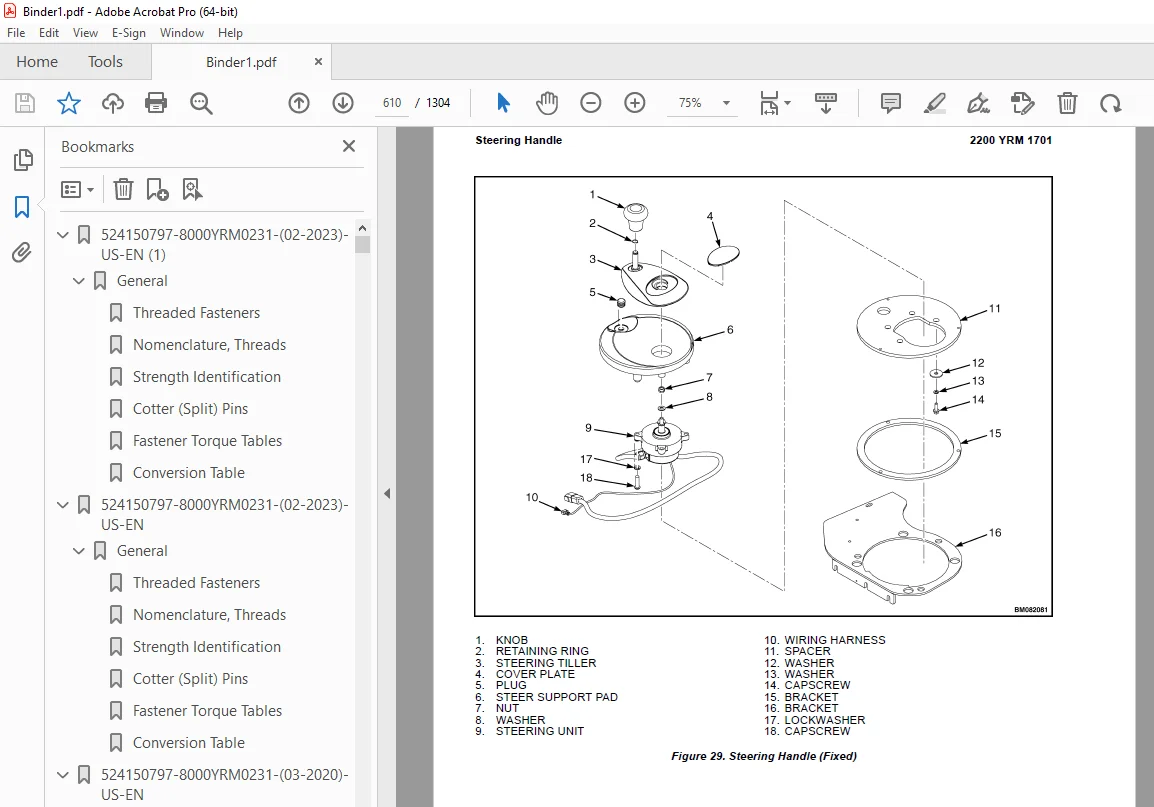
Steering Handle 260
Description 260
Remove 261
Disassemble 262
Assemble 265
Install 265
Steering Controller 266
Description 266
Remove 266
Install 266
Steering Proximity Switch 267
Replace 267
Steering Motor 268
Description 268
Remove 268
Disassemble 268
Assemble 269
Install 269
Troubleshooting 270
550101335-1600YRM1696-(05-2015)-US-EN 273
General 277
Discharging the Capacitors 278
Raising the Lift Truck 279
How to Raise the Drive Tire End 279
How to Raise the Entire Lift Truck 280
Description 280
Steering Handle Assembly 282
Steering Handle 282
Description 282
Remove 283
Disassemble 284
Assemble 287
Install 287
Steering Controller 288
Description 288
Remove 288
Install 288
Steering Proximity Switch 289
Replace 289
Steering Motor 290
Description 290
Remove 290
Disassemble 290
Assemble 291
Install 291
Troubleshooting 292
550101336-1800YRM1697-(03-2022)-US-EN (1) 295
General 301
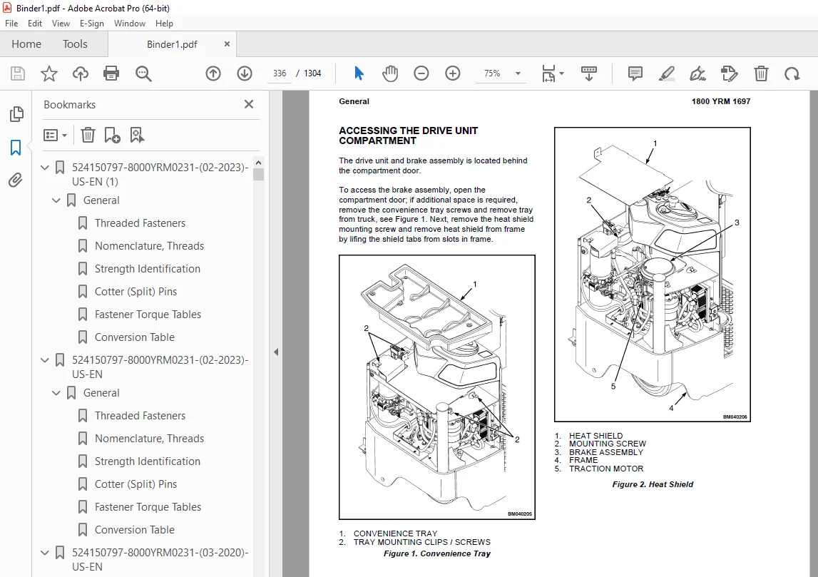
Accessing the Drive Unit Compartment 301
Description 303
Special Precautions 304
Repair 305
Air Gap 305
Brake Hub Alignment 306
Remove 24V Brake Assembly 306
Remove 2-Stage Brake Assembly 308
Install 24V Brake Assembly 309
Install 2-Stage Brake Assembly 309
Troubleshooting 310
550101336-1800YRM1697-(03-2022)-US-EN 313
General 319
Accessing the Drive Unit Compartment 319
Description 321
Special Precautions 322
Repair 323
Air Gap 323
Brake Hub Alignment 324
Remove 24V Brake Assembly 324
Remove 2-Stage Brake Assembly 326
Install 24V Brake Assembly 327
Install 2-Stage Brake Assembly 327
Troubleshooting 328
550101336-1800YRM1697-(06-2014)-US-EN 331
550101337-1900YRM1698-(06-2014)-US-EN (1) 345
550101337-1900YRM1698-(06-2014)-US-EN 373
550101338-2200YRM1699-(09-2014)-US-EN (1) 401
550101338-2200YRM1699-(09-2014)-US-EN 417
550101339-2200YRM1700-(04-2020)-US-EN (1) 433
General 439
Introduction 439
Description 439
Button Keypad 439
LED Indicator Lights 439
LCD Screen 439
Dash Display Menu Access 439
Menu Navigation 440
Dash Display Menu Operation 440
Nodes 440
Menu Structure 440
Service-Level Menu 441
Hour Meters 442
H1 Truck Hours 443
H2 Traction Hours 443
H3 Pump Hours 443
H4 Steer Hours 443
H5 Odometer Hours 443
H10 Display Hours 443
H32 Combination Node Hours 443
H40 Steer Node Hours 443
Performance 444
Performance Level 1 444
P1 1 Forward 445
P1 2 Reverse 445
P1 3 Acceleration 445
P1 4 Plug 445
P1 5 Coast 445
P1 32 Steer Effort 445
P1 33 Steer Ratio 445
Operator Passwords 446
Add Password 446
Delete Password 446
Edit Password 446
Operator Password 446
Clear Log 447
Operator Logs 447
Operator 1-150 447
Information 447
I3 Serial Number 447
I5 Truck Voltage 447
Settings 448
S1 Metric 449
S2 User Performance 449
S3 Timeout 449
S4 Battery Type 449
S5 BDI Startup Full 449
S6 BDI Full 449
S7 BDI Empty 449
S8 BDI Reset 450
S9 Lift Interrupt 450
S10 Audible Warning 450
S11 Visual Warning 450
S12 Checklist 450
S13 Maint Reminder 450
S14 Restore Default 450
S15 Truck Lockout 451
S23 Set Steer 0 Positive 451
S25 Max CW Angle Fine 451
S27 Max CCW Angle Fine 451
S61 Extended Shift 451
Software Versions 451
Error Log 451
(E1) Error Log 1 452
Error 1 1 (E1 1) 452
Error 1 2 (E1 2) 452
Error 1 3 (E1 3) 452
Error 1 4 (E1 4) 452
Diagnostics 453
Diagnostics 453
D1 Status 453
D2 Input 453
D3 Output 453
D1 Status 453
D1 1 CAN 454
D1 2 Contactor 454
D1 3 Full Traction 454
D1 4 Limp Traction 454
D1 5 Steering 454
D1 6 Lift 454
D1 7 Lower 454
D2 Inputs 455
D2 10 Display 455
D2 10 1 Bus Error 455
D2 10 2 Bus Max Error 455
D2 10 32 Combination Controller 455
D2 10 40 Steer 455
D2 32 Combination Controller 456
D2 32 1 Target Speed 458
D2 32 2 Motor Speed 458
D2 32 3 Motor Encoder 458
D2 32 5 Controller Temperature 458
D2 32 6 Motor Temperature 458
D2 32 7 Motor Current 458
D2 32 8 Cap Voltage 458
D2 32 9 Cap Maximum Voltage 458
D2 32 10 Cap Minimum Voltage 458
D2 32 14 MC Connect 458
D 2 32 16 Horn Switch 458
D2 32 17 Brake Switch 458
D2 32 20 Pump Current 458
D2 32 28 Steer Status 458
D2 32 32 SOC 458
D2 32 33 Operator Sensor Switch 458
D2 32 34 Traction Input 458
D2 32 35 Lift/Lower Input 458
D2 32 36 Work Light Auto Switch 459
D2 32 37 Work Light Manual Switch 459
D2 32 38 Light Sensor 459
D2 40 Steer 459
D2 40 1 Target Speed 460
D2 40 2 Motor Speed 460
D2 40 3 Motor Encoder 461
D2 40 5 Controller Temperature 461
D2 40 7 Motor Temperature 461
D2 40 8 Cap Voltage 461
D2 40 9 Cap Maximum Voltage 461
D2 40 10 Cap Minimum Voltage 461
D2 40 11 Key Voltage 461
D2 40 12 Key Max Voltage 461
D2 40 13 Key Minimum Voltage 461
D2 40 17 Center Prox SW 461
D2 40 19 Steer Angle 461
D2 40 28 Pressure Sensor 461
D2 40 29 Steer Input A 461
D2 40 30 Steer Input B 461
D3 Output 462
D3 10 Display 462
D3 10 10 Display Com 462
D3 10 32 Combination Com 462
D3 10 40 Steer Com 462
D3 32 Combination Controller 463
D3 32 1 U-V Line DC Curr 464
D3 32 2 U-W Line DC Curr 464
D3 32 3 V-W Line DC Curr 464
D3 32 7 Pump Motor Short 464
D3 32 9 Load Hold 464
D3 32 10 Backup Alarm 464
D3 32 11 Strobe 464
D3 32 12 Horn 464
D3 40 Steer 464
D3 40 1 U-V Line DC Current 465
D3 40 2 U-W Line DC Current 465
D3 40 3 V-W Line DC Current 465
D3 40 4 Motor Open 465
D3 40 5 Motor Circuit 465
D3 40 6 Status Line 465
Calibration 465
550101339-2200YRM1700-(04-2020)-US-EN 469
General 475
Introduction 475
Description 475
Button Keypad 475
LED Indicator Lights 475
LCD Screen 475
Dash Display Menu Access 475
Menu Navigation 476
Dash Display Menu Operation 476
Nodes 476
Menu Structure 476
Service-Level Menu 477
Hour Meters 478
H1 Truck Hours 479
H2 Traction Hours 479
H3 Pump Hours 479
H4 Steer Hours 479
H5 Odometer Hours 479
H10 Display Hours 479
H32 Combination Node Hours 479
H40 Steer Node Hours 479
Performance 480
Performance Level 1 480
P1 1 Forward 481
P1 2 Reverse 481
P1 3 Acceleration 481
P1 4 Plug 481
P1 5 Coast 481
P1 32 Steer Effort 481
P1 33 Steer Ratio 481
Operator Passwords 482
Add Password 482
Delete Password 482
Edit Password 482
Operator Password 482
Clear Log 483
Operator Logs 483
Operator 1-150 483
Information 483
I3 Serial Number 483
I5 Truck Voltage 483
Settings 484
S1 Metric 485
S2 User Performance 485
S3 Timeout 485
S4 Battery Type 485
S5 BDI Startup Full 485
S6 BDI Full 485
S7 BDI Empty 485
S8 BDI Reset 486
S9 Lift Interrupt 486
S10 Audible Warning 486
S11 Visual Warning 486
S12 Checklist 486
S13 Maint Reminder 486
S14 Restore Default 486
S15 Truck Lockout 487
S23 Set Steer 0 Positive 487
S25 Max CW Angle Fine 487
S27 Max CCW Angle Fine 487
S61 Extended Shift 487
Software Versions 487
Error Log 487
(E1) Error Log 1 488
Error 1 1 (E1 1) 488
Error 1 2 (E1 2) 488
Error 1 3 (E1 3) 488
Error 1 4 (E1 4) 488
Diagnostics 489
Diagnostics 489
D1 Status 489
D2 Input 489
D3 Output 489
D1 Status 489
D1 1 CAN 490
D1 2 Contactor 490
D1 3 Full Traction 490
D1 4 Limp Traction 490
D1 5 Steering 490
D1 6 Lift 490
D1 7 Lower 490
D2 Inputs 491
D2 10 Display 491
D2 10 1 Bus Error 491
D2 10 2 Bus Max Error 491
D2 10 32 Combination Controller 491
D2 10 40 Steer 491
D2 32 Combination Controller 492
D2 32 1 Target Speed 494
D2 32 2 Motor Speed 494
D2 32 3 Motor Encoder 494
D2 32 5 Controller Temperature 494
D2 32 6 Motor Temperature 494
D2 32 7 Motor Current 494
D2 32 8 Cap Voltage 494
D2 32 9 Cap Maximum Voltage 494
D2 32 10 Cap Minimum Voltage 494
D2 32 14 MC Connect 494
D 2 32 16 Horn Switch 494
D2 32 17 Brake Switch 494
D2 32 20 Pump Current 494
D2 32 28 Steer Status 494
D2 32 32 SOC 494
D2 32 33 Operator Sensor Switch 494
D2 32 34 Traction Input 494
D2 32 35 Lift/Lower Input 494
D2 32 36 Work Light Auto Switch 495
D2 32 37 Work Light Manual Switch 495
D2 32 38 Light Sensor 495
D2 40 Steer 495
D2 40 1 Target Speed 496
D2 40 2 Motor Speed 496
D2 40 3 Motor Encoder 497
D2 40 5 Controller Temperature 497
D2 40 7 Motor Temperature 497
D2 40 8 Cap Voltage 497
D2 40 9 Cap Maximum Voltage 497
D2 40 10 Cap Minimum Voltage 497
D2 40 11 Key Voltage 497
D2 40 12 Key Max Voltage 497
D2 40 13 Key Minimum Voltage 497
D2 40 17 Center Prox SW 497
D2 40 19 Steer Angle 497
D2 40 28 Pressure Sensor 497
D2 40 29 Steer Input A 497
D2 40 30 Steer Input B 497
D3 Output 498
D3 10 Display 498
D3 10 10 Display Com 498
D3 10 32 Combination Com 498
D3 10 40 Steer Com 498
D3 32 Combination Controller 499
D3 32 1 U-V Line DC Curr 500
D3 32 2 U-W Line DC Curr 500
D3 32 3 V-W Line DC Curr 500
D3 32 7 Pump Motor Short 500
D3 32 9 Load Hold 500
D3 32 10 Backup Alarm 500
D3 32 11 Strobe 500
D3 32 12 Horn 500
D3 40 Steer 500
D3 40 1 U-V Line DC Current 501
D3 40 2 U-W Line DC Current 501
D3 40 3 V-W Line DC Current 501
D3 40 4 Motor Open 501
D3 40 5 Motor Circuit 501
D3 40 6 Status Line 501
Calibration 501
550101340-2200YRM1701-(03-2022)-US-EN (1) 505
General 513
Accessing the Drive Unit Compartment 514
Special Precautions 515
Discharging the Internal Capacitors 515
Major Electrical System Features 516
Integrated System 516
CANbus Advantages 516
CANbus Communications 516
Electric Steering 516
Centering Proximity Sensor 516
Traction 517
Combi 517
Input Devices 517
Output Devices 517
Encoder Integrity 517
Test Encoders 517
Proximity Switches 518
Key Switch 518
Multifunction Displays 518
BDI 518
Speed 518
Steer Angle 518
Truck Hours 518
Operational Mode 518
Setup 519
Setup Instructions 519
Combi Traction/Hydraulic Control Unit 519
Normal Operation 519
Display 519
Password Access 519
Startup Checklist 519
Truck Operation Mode 520
Diagnostics 520
Calibration 521
Traction Throttle 521
Lift/Lower 521
Contactor and Electrical Panel Checks 522
Contactors 522
General 522
Test 522
Tips 523
Disassemble and Assemble 523
Repairs 525
Controller, Replace 525
Remove 525
Install 527
Steering Controller, Replace 527
Remove 527
Install 529
HVC Controller, Replace 529
Remove 529
Install 529
Display 529
Contactor Coil, Check 530
Fuses 530
Key Switch 530
Replace 530
Power Disconnect Switch 532
Replace 532
Multifunction Controls 534
Multifunction Control Handle (Before February 2022) 534
Remove 534
Install 536
Multifunction Control Handle (After February 2022) 536
Multifunction Control Handle (After February 2022) 536
Inspection 537
Remove 537
Install 539
Multifunction Control Handle Adjustable Armrest (After February 2022) 539
Remove 540
Disassemble 540
Assemble 542
Install 542
Multifunction Control Handle Disassembly and Repair (After February 2022) 543
Handle Grip and Switch Repairs 543
Handle Grip Support Mounting 543
Handle Disassembly 544
Steering Handle 547
Steering Unit Repair 547
Foot Switches 551
Brake Switch 551
Operator Sensing (Before February 2022) 552
Repair 552
Operator Sensing System (After February 2022) 554
General 554
Remove 555
Install and Adjust 555
Dash Display Assembly 556
Description 556
Remove 556
Test 557
Install 557
Horn 558
Replace 558
Light Assemblies 558
Front Lights 558
Bulb Replacement (Before February 2022) 558
Assembly Replacement (Before February 2022) 559
Bulb and Assembly Replacement (After February 2022) 559
Ultrasonic Sensor Replacement (After February 2022) 560
Caution Light (Before February 2022) 561
Caution Light 561
Light Switches 561
Cooling Fans 563
Operator Fan 563
Repair 563
Proximity Switch (Steering) 564
Remove 564
Install 564
Troubleshooting 564
550101340-2200YRM1701-(03-2022)-US-EN 567
General 575
Accessing the Drive Unit Compartment 576
Special Precautions 577
Discharging the Internal Capacitors 577
Major Electrical System Features 578
Integrated System 578
CANbus Advantages 578
CANbus Communications 578
Electric Steering 578
Centering Proximity Sensor 578
Traction 579
Combi 579
Input Devices 579
Output Devices 579
Encoder Integrity 579
Test Encoders 579
Proximity Switches 580
Key Switch 580
Multifunction Displays 580
BDI 580
Speed 580
Steer Angle 580
Truck Hours 580
Operational Mode 580
Setup 581
Setup Instructions 581
Combi Traction/Hydraulic Control Unit 581
Normal Operation 581
Display 581
Password Access 581
Startup Checklist 581
Truck Operation Mode 582
Diagnostics 582
Calibration 583
Traction Throttle 583
Lift/Lower 583
Contactor and Electrical Panel Checks 584
Contactors 584
General 584
Test 584
Tips 585
Disassemble and Assemble 585
Repairs 587
Controller, Replace 587
Remove 587
Install 589
Steering Controller, Replace 589
Remove 589
Install 591
HVC Controller, Replace 591
Remove 591
Install 591
Display 591
Contactor Coil, Check 592
Fuses 592
Key Switch 592
Replace 592
Power Disconnect Switch 594
Replace 594
Multifunction Controls 596
Multifunction Control Handle (Before February 2022) 596
Remove 596
Install 598
Multifunction Control Handle (After February 2022) 598
Multifunction Control Handle (After February 2022) 598
Inspection 599
Remove 599
Install 601
Multifunction Control Handle Adjustable Armrest (After February 2022) 601
Remove 602
Disassemble 602
Assemble 604
Install 604
Multifunction Control Handle Disassembly and Repair (After February 2022) 605
Handle Grip and Switch Repairs 605
Handle Grip Support Mounting 605
Handle Disassembly 606
Steering Handle 609
Steering Unit Repair 609
Foot Switches 613
Brake Switch 613
Operator Sensing (Before February 2022) 614
Repair 614
Operator Sensing System (After February 2022) 616
General 616
Remove 617
Install and Adjust 617
Dash Display Assembly 618
Description 618
Remove 618
Test 619
Install 619
Horn 620
Replace 620
Light Assemblies 620
Front Lights 620
Bulb Replacement (Before February 2022) 620
Assembly Replacement (Before February 2022) 621
Bulb and Assembly Replacement (After February 2022) 621
Ultrasonic Sensor Replacement (After February 2022) 622
Caution Light (Before February 2022) 623
Caution Light 623
Light Switches 623
Cooling Fans 625
Operator Fan 625
Repair 625
Proximity Switch (Steering) 626
Remove 626
Install 626
Troubleshooting 626
550101340-2200YRM1701-(09-2014)-US-EN 629
550101341-4000YRM1702-(02-2016)-US-EN (1) 667
General 671
Description of Operation 671
Load Wheel 672
Remove 672
Install 672
Caster Adjustment 675
Casters 675
Caster Adjustment Check 675
Caster Adjust Procedure 676
Caster Repair 678
Caster Replacement 678
Disassemble 679
Assemble 679
Rear Link and Load Wheel 679
Remove 679
Install 681
Pull Rod 682
Remove 683
End Replacement 683
Install 683
Fork Height Adjustment 684
Rocker Arm 685
Remove 685
Install 686
Upper Link 687
Remove 687
Install 687
Entry Rollers 688
Replacement 688
Troubleshooting 689
550101341-4000YRM1702-(02-2016)-US-EN 693
General 697
Description of Operation 697
Load Wheel 698
Remove 698
Install 698
Caster Adjustment 701
Casters 701
Caster Adjustment Check 701
Caster Adjust Procedure 702
Caster Repair 704
Caster Replacement 704
Disassemble 705
Assemble 705
Rear Link and Load Wheel 705
Remove 705
Install 707
Pull Rod 708
Remove 709
End Replacement 709
Install 709
Fork Height Adjustment 710
Rocker Arm 711
Remove 711
Install 712
Upper Link 713
Remove 713
Install 713
Entry Rollers 714
Replacement 714
Troubleshooting 715
550101342-8000YRM1703-(03-2022)-US-EN (1) 719
Hydraulic System 725
Hydraulic Oils 725
Gear Oils 725
Grease 726
Truck Weight 726
Tire Sizes 727
Torque Specifications 728
Drive Wheel Assembly 728
Master Drive Unit 728
Traction Motor 728
Steering System 728
Electrical 728
Lift Mechanism 728
Hydraulics 728
Battery Specifications 729
550101342-8000YRM1703-(03-2022)-US-EN 731
Hydraulic System 737
Hydraulic Oils 737
Gear Oils 737
Grease 738
Truck Weight 738
Tire Sizes 739
Torque Specifications 740
Drive Wheel Assembly 740
Master Drive Unit 740
Traction Motor 740
Steering System 740
Electrical 740
Lift Mechanism 740
Hydraulics 740
Battery Specifications 741
550101342-8000YRM1703-(06-2014)-US-EN 743
550101343-8000YRM1704-(03-2022)-US-EN (1) 755
Schematic / Diagram 761
550101343-8000YRM1704-(03-2022)-US-EN 809
Schematic / Diagram 815
550101343-8000YRM1704-(12-2016)-US-EN 863
Schematic / Diagram 867
550101344-8000YRM1705-(03-2021)-US-EN 901
General 905
Operator’s Compartment Covers/Console 905
Operator’s Compartment Covers 905
Remove 905
Install 906
Operator’s Compartment Console 906
Remove 906
Install 908
Console Tray 908
Remove 908
Install 908
Drive Unit Compartment Door 909
Caster Wheel Cover 909
How to Move a Disabled Truck 909
How to Tow the Lift Truck 910
How to Put a Lift Truck on Blocks 910
How to Raise Drive/Steer Tire 910
How to Raise Load Wheels 911
Special Precautions 911
Discharging the Capacitors 911
Welding Repairs 912
Maintenance Schedule 912
Maintenance Procedures Every 8 Hours or Daily 917
Checks With Key Switch Turned OFF 917
Battery 917
Hydraulic Leaks 918
Drive Tire, Load Wheels, Casters, and Frame 918
Checks With Key Switch Turned ON 919
Operation 919
Maintenance Procedures Every 250 Hours or Every 6 Weeks 921
Caster Lubrication 921
Casters 921
Caster Adjustment Check 921
Caster Adjust Procedure 922
Maintenance Procedures Every 500 Hours or Every 3 Months 924
Hydraulic System 924
Hydraulic Oil 924
Hydraulic Reservoir Breather 924
Steering System 925
Power Steering 925
Lift Linkage and Load Wheels 925
Master Drive Unit 925
Change Gear Oil 925
Check Oil Level 925
Drive Tire Check 926
Maintenance Procedures Every 2000 Hours or Yearly 926
Lubrication 926
Repack Load Wheel Bearings 926
Hydraulic System 926
Oil Change 926
Brake 927
Electrical 927
Battery Maintenance 927
How to Charge the Battery 927
Equalizing Charge 928
Normal Charge 928
How to Change the Battery 928
Transporting 930
Loading 930
Unloading 930
Preparation for Storage 930
Short-Term Storage (1 to 6 months) 931
Long-Term Storage (6 months or longer) 931
Preparation for Use 931
Preparation After Shipment 931
Preparation After Storage 931
550101344-8000YRM1705-(03-2022)-US-EN (1) 933
General 937
Operator’s Compartment Covers/Console 937
Operator’s Compartment Covers 937
Remove 937
Install 940
Operator’s Compartment Console 940
Remove 940
Install 942
Console Tray 943
Remove 943
Install 943
Drive Unit Compartment Door 943
Caster Wheel Cover 943
How to Move a Disabled Truck 944
How to Tow the Lift Truck 944
How to Put a Lift Truck on Blocks 945
How to Raise Drive/Steer Tire 945
How to Raise Load Wheels 945
Special Precautions 946
Discharging the Capacitors 946
Welding Repairs 946
Maintenance Schedule 947
Maintenance Procedures Every 8 Hours or Daily 952
Checks With Key Switch Turned OFF 952
Battery 952
Hydraulic Leaks 953
Drive Tire, Load Wheels, Casters, and Frame 953
Checks With Key Switch Turned ON 954
Operation 954
Maintenance Procedures Every 250 Hours or Every 6 Weeks 956
Caster Lubrication 956
Casters 956
Caster Adjustment Check 956
Caster Adjust Procedure 957
Maintenance Procedures Every 500 Hours or Every 3 Months 960
Hydraulic System 960
Hydraulic Oil 960
Hydraulic Reservoir Breather 960
Steering System 960
Power Steering 960
Lift Linkage and Load Wheels 961
Master Drive Unit 961
Change Gear Oil 961
Check Oil Level 961
Drive Tire Check 963
Maintenance Procedures Every 2000 Hours or Yearly 964
Lubrication 964
Repack Load Wheel Bearings 964
Hydraulic System 964
Oil Change 964
Brake 965
Electrical 965
Battery Maintenance 966
How to Charge the Battery 966
Equalizing Charge 966
Normal Charge 966
How to Change the Battery 967
Transporting 968
Loading 968
Unloading 968
Preparation for Storage 968
Short-Term Storage (1 to 6 months) 969
Long-Term Storage (6 months or longer) 969
Preparation for Use 969
Preparation After Shipment 969
Preparation After Storage 969
550101344-8000YRM1705-(03-2022)-US-EN 971
General 975
Operator’s Compartment Covers/Console 975
Operator’s Compartment Covers 975
Remove 975
Install 978
Operator’s Compartment Console 978
Remove 978
Install 980
Console Tray 981
Remove 981
Install 981
Drive Unit Compartment Door 981
Caster Wheel Cover 981
How to Move a Disabled Truck 982
How to Tow the Lift Truck 982
How to Put a Lift Truck on Blocks 983
How to Raise Drive/Steer Tire 983
How to Raise Load Wheels 983
Special Precautions 984
Discharging the Capacitors 984
Welding Repairs 984
Maintenance Schedule 985
Maintenance Procedures Every 8 Hours or Daily 990
Checks With Key Switch Turned OFF 990
Battery 990
Hydraulic Leaks 991
Drive Tire, Load Wheels, Casters, and Frame 991
Checks With Key Switch Turned ON 992
Operation 992
Maintenance Procedures Every 250 Hours or Every 6 Weeks 994
Caster Lubrication 994
Casters 994
Caster Adjustment Check 994
Caster Adjust Procedure 995
Maintenance Procedures Every 500 Hours or Every 3 Months 998
Hydraulic System 998
Hydraulic Oil 998
Hydraulic Reservoir Breather 998
Steering System 998
Power Steering 998
Lift Linkage and Load Wheels 999
Master Drive Unit 999
Change Gear Oil 999
Check Oil Level 999
Drive Tire Check 1001
Maintenance Procedures Every 2000 Hours or Yearly 1002
Lubrication 1002
Repack Load Wheel Bearings 1002
Hydraulic System 1002
Oil Change 1002
Brake 1003
Electrical 1003
Battery Maintenance 1004
How to Charge the Battery 1004
Equalizing Charge 1004
Normal Charge 1004
How to Change the Battery 1005
Transporting 1006
Loading 1006
Unloading 1006
Preparation for Storage 1006
Short-Term Storage (1 to 6 months) 1007
Long-Term Storage (6 months or longer) 1007
Preparation for Use 1007
Preparation After Shipment 1007
Preparation After Storage 1007
550101345-9000YRM1706-(03-2022)-US-EN (1) 1009
SECTION 9030 Electrical System 1015
Group 03 – General Maintenance and Diagnostic Data 1017
Group 20 – Diagnostic Trouble Codes 1027
550101345-9000YRM1706-(03-2022)-US-EN 1093
SECTION 9030 Electrical System 1099
Group 03 – General Maintenance and Diagnostic Data 1101
Group 20 – Diagnostic Trouble Codes 1111
550101345-9000YRM1706-(12-2017)-US-EN 1177
SECTION 9030 9030 – Electrical System 1183
Group 03 – General Maintenance and Diagnostic Data 1185
Group 20 – Diagnostic Trouble Codes 1195
550267564-0630YRM2448-(09-2022)-US-EN (1) 1261
General 1267
General 1267
Description 1267
Discharging The Capacitors 1268
Master Drive Unit Repair 1272
Maintenance 1272
Draining the Oil 1272
Remove 1272
Disassemble 1274
Clean and Inspect 1275
Assemble 1275
Install 1276
Replace the Wheel Seal on Kordel Drive Units 1276
Tools required 1276
Truck setup 1276
Wheel shaft seal and protection ring removal (method 1) 1277
Wheel shaft seal and protection ring removal (method 2) 1277
Wheel shaft seal and protection ring installation 1279
Troubleshooting 1280
550267564-0630YRM2448-(09-2022)-US-EN 1283
General 1289
General 1289
Description 1289
Discharging The Capacitors 1290
Master Drive Unit Repair 1294
Maintenance 1294
Draining the Oil 1294
Remove 1294
Disassemble 1296
Clean and Inspect 1297
Assemble 1297
Install 1298
Replace the Wheel Seal on Kordel Drive Units 1298
Tools required 1298
Truck setup 1298
Wheel shaft seal and protection ring removal (method 1) 1299
Wheel shaft seal and protection ring removal (method 2) 1299
Wheel shaft seal and protection ring installation 1301
Troubleshooting 1302
S.V 05/24