Yale Forklift A292 (MPE060VG) Service Manual – PDF DOWNLOAD
$31.95
Yale Forklift A292 (MPE060VG) Service Manual – PDF DOWNLOAD
Description
Yale Forklift A292 (MPE060VG) Service Manual – PDF DOWNLOAD
FILE DETAILS:
Yale Forklift A292 (MPE060VG) Service Manual – PDF DOWNLOAD
Language : English
Pages : 624
Downloadable : Yes
File Type : PDF
IMAGES PREVIEW OF THE MANUAL:
TABLE OF CONTENTS:
Yale Forklift A292 (MPE060VG) Service Manual – PDF DOWNLOAD
524150797-8000YRM0231-(02-2023)-US-EN 1
General 7
Threaded Fasteners 7
Nomenclature, Threads 7
Strength Identification 8
Cotter (Split) Pins 9
Fastener Torque Tables 14
Conversion Table 16
524150797-8000YRM0231-(03-2020)-US-EN 23
General 27
Threaded Fasteners 27
Nomenclature, Threads 27
Strength Identification 28
Cotter (Split) Pins 29
Fastener Torque Tables 34
Conversion Table 36
524158040-2240YRM0001-(01-2023)-US-EN 43
General 49
Battery Type 49
Lead-Acid Batteries 49
Lithium-Ion Batteries 50
Specific Gravity 50
Chemical Reaction in a Cell 50
Electrical Terms 52
Battery Selection 53
Battery Voltage 54
Battery as a Counterweight 54
Battery Ratings 54
Kilowatt-Hours 54
Battery Maintenance 55
Safety Procedures 55
Maintenance Records 55
New Battery 55
Cleaning Battery 56
Adding Water to Battery 58
Hydrometer 58
Battery Temperature 59
Charging Battery 60
Types of Battery Charges 61
Methods of Charging 62
Troubleshooting Charger 63
Knowing When Battery Is Fully Charged 63
Where to Charge Batteries 63
Equipment Needed 63
Battery Connectors 64
Battery Care 64
Troubleshooting 66
524158040-2240YRM0001-(03-2020)-US-EN 71
General 75
Battery Type 75
Lead-Acid Batteries 75
Lithium-Ion Batteries 76
Specific Gravity 76
Chemical Reaction in a Cell 76
Electrical Terms 78
Battery Selection 78
Battery Voltage 79
Battery as a Counterweight 80
Battery Ratings 80
Kilowatt-Hours 80
Battery Maintenance 80
Safety Procedures 80
Maintenance Records 81
New Battery 81
Cleaning Battery 81
Adding Water to Battery 83
Hydrometer 84
Battery Temperature 85
Charging Battery 86
Types of Battery Charges 86
Methods of Charging 88
Troubleshooting Charger 88
Knowing When Battery Is Fully Charged 89
Where to Charge Batteries 89
Equipment Needed 89
Battery Connectors 90
Battery Care 90
Troubleshooting 92
524164715-0630YRM0961-(03-2022)-US-EN 97
General 105
Check Oil Level 106
Change Gear Oil MTR005-007-F, MPE060-080-F, MPC060-080-F, MPE060-VG, MPE080-VG, MPE060VH, and MPE080VH 107
Drive Tire 107
Remove 107
Install 107
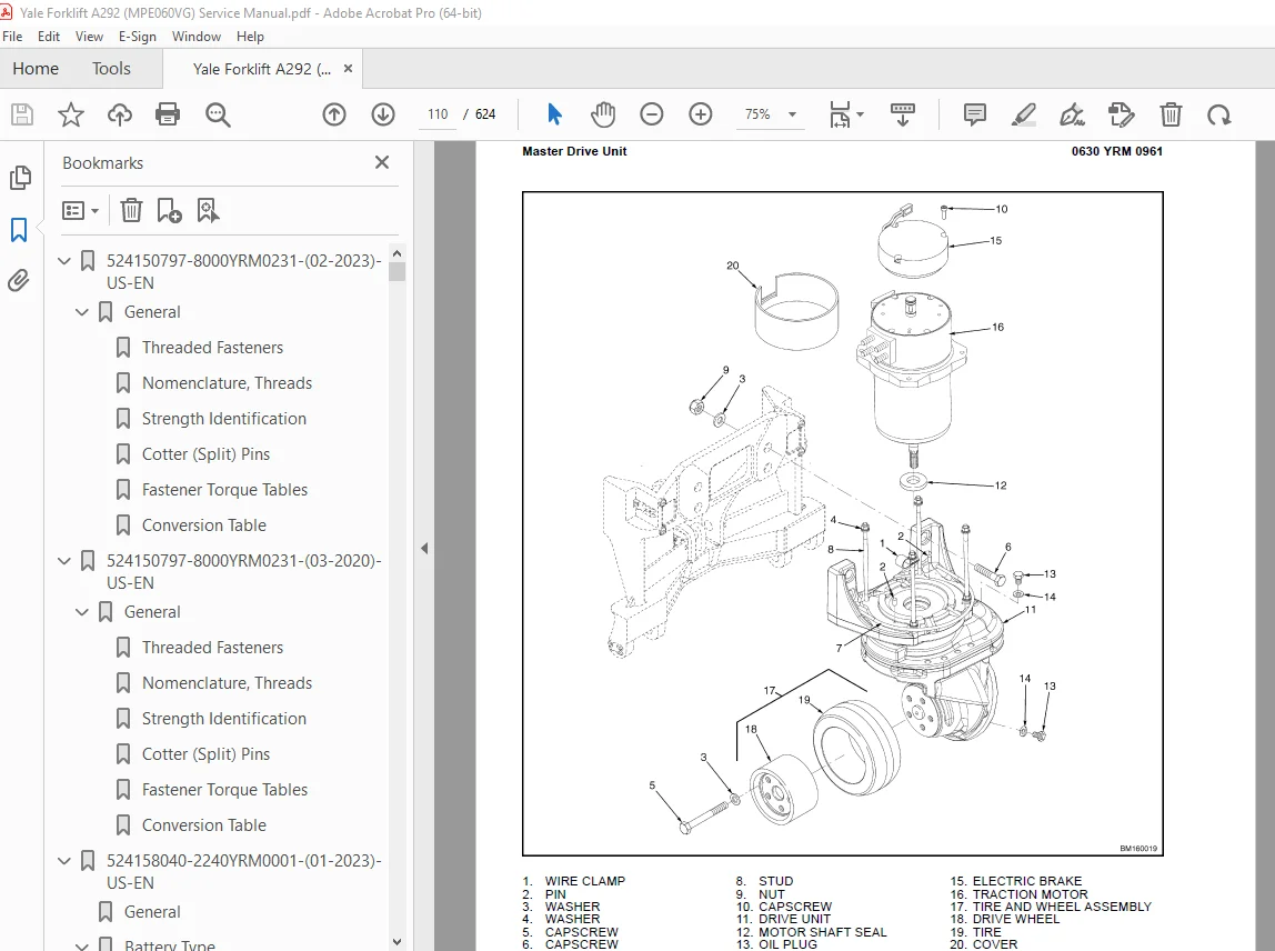
Master Drive Unit 108
Remove 108
Disassemble 115
Remove Drive Axle Group 115
Remove Upper Housing Group 116
Remove Pinion Group 116
Install 118
Troubleshooting 120
524164715-0630YRM0961-(12-2018)-US-EN 123
General 131
Check Oil Level 132
Change Gear Oil MTR005-007-F, MPE060-080-F, MPC060-080-F, MPE060-VG, MPE080-VG, MPE060VH, and MPE080VH 133
Drive Tire 133
Remove 133
Install 133
Master Drive Unit 133
Remove 133
Disassemble 140
Remove Drive Axle Group 140
Remove Upper Housing Group 140
Remove Pinion Group 140
Install 143
Troubleshooting 145
524183085-2200YRM1058-(04-2011)-US-EN 149
toc 149
Troubleshooting and Adjustments Using the AC Controls Program (E 149
Safety Precautions Maintenance and Repair 150
General 153
Computer Requirements 153
Software, Install 153
Language Selection 153
Demo Mode 154
Connect PC to Lift Truck 158
Starting AC Controls Program 160
Lift Truck Control Setup 165
Change Lift Truck Serial Number or Hourmeter 165
Setting Factory Default Values or Changing Lift Truck Parameters 166
Create New Custom Lift Truck Configuration 172
Lift Truck Configuration Properties 175
Import New Lift Truck Configuration From Disk 178
Delete Custom Lift Truck Configuration or Password File 180
Dash Display 183
Custom Display Languages 183
Download Display Language 185
Clear Operator Log 185
Password Functions 188
Enable/Disable Password and Lift Truck Inspection Functions 188
Truck Inspection Checklist 188
Password 188
Password Properties 188
Create New Password File 193
Download Passwords 194
Upload Passwords 196
Reports Menu 198
Devices Report 198
Custom Report 198
Password Report 198
Operator Report 205
Current Settings Report 208
Status Code Report 212
Status Codes Log 215
Troubleshooting 217
Diagnostics 217
Help Menu 220
General 220
Contents 220
Technical Support 220
About Electric Truck AC Controls Program 220
524274698-8000YRM1288-(08-2012)-US-EN 227
toc 227
Diagrams 227
Safety Precautions Maintenance and Repair 228
524274699-0620YRM1283-(12-2018)-US-EN 247
General 251
Accessing the Drive Unit Compartment 251
MPE060VG and MPE080VGMPE060VH and MPE080VH 251
MPC060/080-F and MTR005/007-F 252
Special Precautions 254
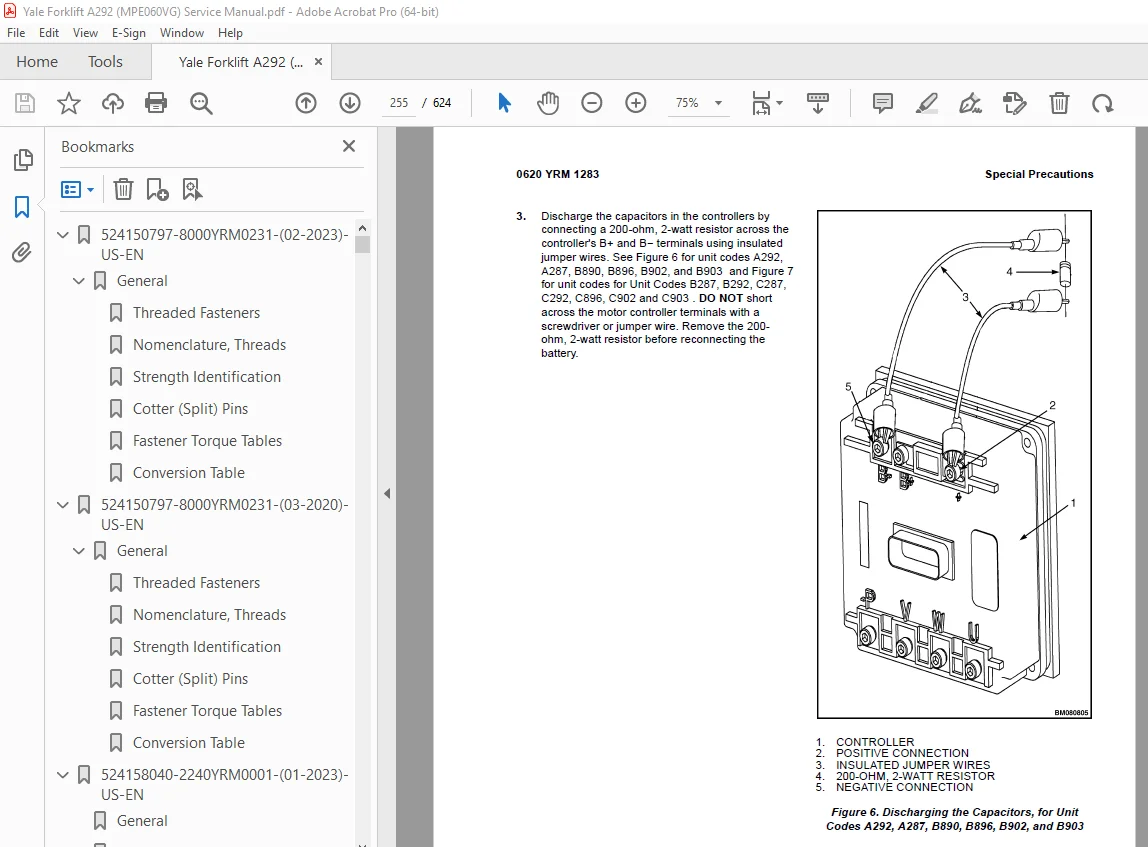
Discharging the Capacitors 254
Description 256
AC Motor Repair 256
Remove 256
Disassemble 257
Inspect 259
Assemble 259
Install 259
Troubleshooting 260
524274701-1800YRM1285-(04-2011)-US-EN 265
toc 265
Brakes 265
Safety Precautions Maintenance and Repair 266
General 269
Accessing the Drive Unit Compartment 269
MPE060/080-F, MPE060-VG, and MPE080-VG 269
MPC060/080-F and MTR005/007-F 270
Description 271
Special Precautions 273
Brake Check 274
Brake Release 274
Brake Apply 274
Air Gap 274
Hold On Grade Test 276
Brake Assembly Repair 276
MPE060-F, MPC060-F, MTR005-F, and MPE060-VG 276
Remove 276
Repair 277
Install 277
MPE080-F, MPC080-F, MTR007-F, and MPE080-VG 278
Remove 278
Repair 278
Install 279
Troubleshooting 280
tables 265
Table 1 Stator Resistance 274
Table 2 Adjustment Specifications 275
524274702-2200YRM1286-(04-2011)-US-EN 285
toc 285
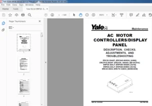
AC Motor Controller 285
Safety Precautions Maintenance and Repair 286
General 289
Discharging the Capacitors 289
Description 290
Electrical System 290
AC Traction Motor 291
Controller 291
Service PC Connection 291
Parameters 291
General 291
Parameter Description 293
Parameters 293
Extended Shift 293
Walk Speed (Both Directions) 293
Hi Speed (FWD) 293
Hi Speed (REV) 293
Minimum Acceleration 293
Maximum Acceleration 293
Plugging 293
ADS-Neutral 293
ADS-Throttle 293
Pick Acceleration 293
Pick Deceleration 294
Battery Full Voltage 294
Lift Interrupt 294
Troubleshooting 294
General 294
Non-Status Code Errors 295
Powered Black Screen 295
Tiller Oscillation and Bias (EPAS Option) 296
Status Codes 296
Electrical Checks 389
General Electrical System Checks 389
Static Checks on Power and Ground Connections 389
Static Checks on CAN Connections 390
Tiller Harness Shorts and Continuity Checks 391
Control Card Functional Test 392
Dash Display 394
General 394
Startup 395
Status LED 395
Performance Mode Indicator 395
Hourmeter 395
Battery Charge Indicator 396
Fault Log 396
Connector Pin-Outs 397
System Logic Diagram 399
tables 285
Table 1 Parameter Default Values 292
Table 2 Fault Codes 297
524290090-2200YRM1323-(04-2011)-US-EN 403
toc 403
User Interface 403
Safety Precautions Maintenance and Repair 404
General 407
Description 407
Dash Display Menu Access (Standard Handle) 407
Dash Display Menu Access (Metal Handle Option) 408
Menu Navigation 409
Standard Handle 409
Metal Handle Option 411
Dash Display Versions 412
Supervisor Menu 413
View Versions 414
Hourmeters 414
Diagnostics 414
Fault Log 415
Controller Inputs 416
Control Handle Inputs 416
Run Diagnostics 417
Traction Motor 418
Pump Motor and Valve 418
Control Handle 418
Temperatures 419
Power Steering 419
Service Reminder 420
Change Supervisor Password 420
Operator Modes 421
Exit to Run Mode 421
tables 403
Table 1 Corresponding Buttons 411
Table 2 Supervisor Menu 413
Table 3 Diagnostics Menu 415
Table 4 Controller Inputs 416
Table 5 Control Handle Inputs 416
Table 6 Run Diagnostics Menu 417
524290091-2200YRM1324-(10-2012)-US-EN 425
toc 425
User Interface 425
Safety Precautions Maintenance and Repair 426
General 429
Description 429
Dash Display Menu Access (Standard Handle) 429
Dash Display Menu Access (Metal Handle Option) 430
Menu Navigation 431
Standard Handle 431
Metal Handle Option 433
Dash Display Versions 434
Technician Menu 435
View Versions 436
Hourmeters 436
Diagnostics 437
Fault Log 437
Controller Inputs 438
Control Handle Inputs 438
Run Diagnostics 439
Traction Motor 440
Pump Motor and Valve 441
Control Handle 441
Traction Temps 441
Power Steering 442
Service Reminder 442
Change Supervisor Password 443
Operator Modes 443
Set Performance 444
Extended Shift 445
Walk Speed 446
High Speed (FWD) 446
High Speed (REV) 446
Minimum Acceleration 447
Maximum Acceleration 447
Plugging 447
ADS-Neutral 448
ADS-Throttle 448
Pick Acceleration 448
Pick Deceleration 449
Battery Full 449
Lift Interrupt 449
Min Steer Assist FWD (Power Steering Assist Only) 450
Min Steer Assist REV (Power Steering Assist Only) 450
Max Steer Assist (Power Steering Assist Only) 450
Defaults 451
Save and Exit 451
Exit Without Saving 451
Set General Items 452
A/V Alarm (Audible/Visual) 452
Clear Fault Log 453
Calibrations 453
Throttle 454
MPE060-80F and MPE060-80VG Composite Handle ( ⇒ S/N B890N02938 454
MPE060-80F and MPE060-80VG Composite Handle ( S/N B890N02939J, B 454
MPE060-80F and MPE060-80VG Metal Handle 455
Steer Handle (Power Steering Assist Only) 456
Change Service Technician Password 456
Exit to Run Mode 457
tables 425
Table 1 Corresponding Buttons 433
Table 2 Technician Menu 435
Table 3 Diagnostics Menu 437
Table 4 Controller Inputs 438
Table 5 Control Handle Inputs 438
Table 6 Run Diagnostics Menu 440
Table 7 Performance Parameters 444
Table 8 Set Performance Menu 444
Table 9 Set General Items Menu 452
Table 10 Calibrations Menu 453
550025465-8000YRM1453-(04-2011)-US-EN 461
toc 461
Periodic Maintenance 461
Safety Precautions Maintenance and Repair 462
General 465
How to Move a Disabled Truck 465
How to Tow the Lift Truck 466
How to Put a Lift Truck on Blocks 466
How to Raise Drive/Steer Tire 466
How to Raise Load Wheels 467
Accessing the Drive Unit Compartment 467
Special Precautions 468
Discharging the Capacitors 468
Welding Repairs 470
Maintenance Schedule 470
Maintenance Procedures Every 8 Hours or Daily 474
Checks With Key Switch Turned OFF 474
Battery 474
Hydraulic Leaks 475
Drive Tire, Load Wheels, Casters, and Frame 475
Checks With Key Switch Turned ON 476
Operation 476
Maintenance Procedures Every 250 Hours or Every 6 Weeks 477
Caster Lubrication 477
Maintenance Procedures Every 500 Hours or Every 3 Months 478
Hydraulic System 478
Hydraulic Oil 478
Hydraulic Reservoir Breather 478
Steering System 478
Power Assist Steering 478
Lift Linkage and Load Wheels 479
Casters 479
Caster Adjustment Check 479
Caster Adjust Heavy-Duty 479
Master Drive Unit 480
Change Gear Oil 480
Check Oil Level 480
Drive Tire Check 481
Maintenance Procedures Every 2000 Hours or Yearly 481
Lubrication 481
Repack Load Wheel Bearings 481
Repack Steer Bearings (Manual Steer Only) 481
Hydraulic System 481
Oil Change 481
Brake 482
Electrical 482
MDU 482
Oil Change 482
Battery Maintenance 483
How to Charge the Battery 483
Equalizing Charge 483
Normal Charge 484
How to Change the Battery 484
Transporting 485
Loading 485
Unloading 485
Preparation for Storage 486
Short-Term Storage (1 to 6 months) 486
Long-Term Storage (6 months or longer) 486
Preparation for Use 486
Preparation After Shipment 486
Preparation After Storage 486
tables 461
Table 1 Maintenance Schedule 471
Table 2 Specific Gravity Corrections 483
550025475-0100YRM1448-(04-2011)-US-EN 489
toc 489
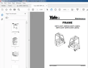
Frame 489
Safety Precautions Maintenance and Repair 490
General 493
Frame Separation and Assembly 494
Disassemble 494
Assemble 494
Painting Instructions 495
Label Replacement 495
550025476-1600YRM1449-(09-2012)-US-EN 499
toc 499
Steering Mechanism 499
Safety Precautions Maintenance and Repair 500
General 503
Accessing the Drive Unit Compartment 503
Special Precautions 504
Electromagnetic Shield 505
Calibration 505
Power Assist Steering 505
Control Handle 506
Control Handle Head 506
Control Handle 506
Standard Steering 506
Remove 506
Install 507
Power Assist Steering 508
Remove 508
Install 509
Gas Spring 511
Discharging the Gas Spring 511
Remove 511
Install 512
Articulating Shaft and Pinions (Power Assist Models) 513
Remove 513
Pinion Repair 513
Upper Pinion 513
Remove 514
Install 514
Lower Pinion 515
Install 516
Steer Motor Assembly 516
Repair 516
Steer Motor, Replace 516
Steer Motor Gear, Replace 517
Gearbox/Complete Assembly, Replace 518
Steer Support Assembly 519
Standard Steering 519
Remove (Complete Unit) 519
Disassemble 519
Assemble 521
Install (Complete Unit) 521
Power Assist Steering (Option) 522
Remove (Complete Unit) 523
Disassemble 523
Support Base 523
Steer Swivel 524
Assemble 524
Steer Swivel 524
Support Base 524
Install (Complete Unit) 528
Electronic Coast Control (Option) 529
Disassemble 529
Assemble 531
Checks 531
Troubleshooting 532
550025477-4000YRM1452-(12-2012)-US-EN 535
toc 535
Lifting Mechanism 535
Safety Precautions Maintenance and Repair 536
General 539
Description of Operation 539
Load Wheel 539
Remove 539
Install 540
Casters 541
Caster Adjustment Check 541
Caster Adjust Heavy-Duty 541
Caster Replacement 541
Disassemble 542
Heavy-Duty 542
Assemble 543
Heavy-Duty 543
Rear Link and Load Wheel 543
Remove 543
Install 543
Pull Rod 547
Remove 547
End Replacement 547
Install 547
Fork Height Adjustment 548
Rocker Arm 549
Remove 549
Install 550
Upper Link 551
Remove 551
Install 551
Entry Rollers 552
Replacement 552
Troubleshooting 553
550025478-8000YRM1454-(04-2011)-US-EN 557
toc 557
Capacities and Specifications 557
Safety Precautions Maintenance and Repair 558
Hydraulic System 561
Hydraulic Oils 561
Gear Oils 562
Grease 562
Truck Weight 562
Tire Sizes 563
Torque Specifications 563
Caster Assembly 563
Drive Wheel Assembly 563
Master Drive Unit 563
Standard Steering 563
Power Assist Steering 564
Brake 564
Electrical 564
Lift Mechanism 564
Hydraulics 564
Battery Specifications 564
tables 557
Table 1 MPE060-VG 565
Table 2 MPE080-VG 565
550026124-1900YRM1450-(04-2011)-US-EN 569
toc 569
Hydraulic System 569
Safety Precautions Maintenance and Repair 570
General 573
Description of Operation 573
Lifting a Load 574
Lowering a Load 574
Hydraulic Lines 574
Hydraulic Oil 574
Clean 574
Sound Level 575
Special Precautions 576
Hydraulic Reservoir 576
Drive Unit Compartment Covers 577
Lift Pump and Motor 578
General 578
Remove 578
Lift Pump and Motor Assembly 578
Disassemble 579
Remove Reservoir 579
Remove Pump Motor 579
Disassemble Pump 579
Assemble 581
Assemble Pump 581
Install Pump Motor 581
Install Reservoir to Pump 581
Install 582
Lift Pump and Motor Assembly 582
Valve Repair 583
Lowering Valve 583
Remove 583
Install 583
Relief Valve 583
Remove 583
Install 584
Check Valve 584
Remove 584
Install 584
Lift Cylinder 585
Remove 585
Disassemble 586
Assemble 586
Install 586
Relief Valve Pressure Check 587
Relief Valve Adjust 588
Troubleshooting 589
Lift Assemblies 589
Lift Cylinders 590
Lift Pump and Motor Assembly 591
550026125-2200YRM1451-(04-2011)-US-EN 597
toc 597
Electrical System 597
Safety Precautions Maintenance and Repair 598
General 601
Accessing the Drive Unit Compartment 602
Special Precautions 603
Discharging the Capacitors 603
Electromagnetic Shield 604
Electrical System Checks 604
Safety Precautions 604
Calibration 606
Power Assist Steering Sensor 606
Repairs 607
Controller, Replace 607
Remove 607
Install 608
Contactor Coil, Check 609
Fuses 609
Horn 610
Replace 610
Brake Switch Operation 610
Brake and Interlock Switches 611
Standard Steering 611
Power Assist Steering 611
Height Limit 612
Control Handle (Standard) 613
Disassemble 613
Assemble 613
Control Handle (HD Option) 614
Disassemble 614
Remove Top Cover 614
Remove Function Switches 615
Remove Throttle Sensor Assembly 615
Remove Handle Shaft Assembly 616
Remove Quick Pick Switches 616
Remove the Coast Control Switches 616
Assemble 617
Install the Coast Control Switches 617
Install Quick Pick Switches 617
Install Handle Shaft Assembly 617
Install Throttle Sensor Assembly 617
Install Function Switches 618
Install Top Cover 618
Control Module 619
Check 619
Remove 620
Install 620
Proximity Switch (Power Assist Steering) 621
Remove 621
Install 621
Remote Control Box Switches 622
Remove 622
Install 622
Troubleshooting 622
tables 597
Table 1 Voltage Checks 606
Table 2 Input Connector Voltages 620
S.V 05/24