Yale Forklift A372 (MPC060VG, MPC080VG) Service Manual – PDF DOWNLOAD
$29.95
Yale Forklift A372 (MPC060VG, MPC080VG) Service Manual – PDF DOWNLOAD
Description
Yale Forklift A372 (MPC060VG, MPC080VG) Service Manual – PDF DOWNLOAD
FILE DETAILS:
Yale Forklift A372 (MPC060VG, MPC080VG) Service Manual – PDF DOWNLOAD
Language : English
Pages : 452
Downloadable : Yes
File Type : PDF
IMAGES PREVIEW OF THE MANUAL:
TABLE OF CONTENTS:
Yale Forklift A372 (MPC060VG, MPC080VG) Service Manual – PDF DOWNLOAD
524150797-8000YRM0231-(02-2023)-US-EN 1
General 7
Threaded Fasteners 7
Nomenclature, Threads 7
Strength Identification 8
Cotter (Split) Pins 9
Fastener Torque Tables 14
Conversion Table 16
524150797-8000YRM0231-(03-2020)-US-EN 23
General 27
Threaded Fasteners 27
Nomenclature, Threads 27
Strength Identification 28
Cotter (Split) Pins 29
Fastener Torque Tables 34
Conversion Table 36
524158040-2240YRM0001-(01-2023)-US-EN 43
General 49
Battery Type 49
Lead-Acid Batteries 49
Lithium-Ion Batteries 50
Specific Gravity 50
Chemical Reaction in a Cell 50
Electrical Terms 52
Battery Selection 53
Battery Voltage 54
Battery as a Counterweight 54
Battery Ratings 54
Kilowatt-Hours 54
Battery Maintenance 55
Safety Procedures 55
Maintenance Records 55
New Battery 55
Cleaning Battery 56
Adding Water to Battery 58
Hydrometer 58
Battery Temperature 59
Charging Battery 60
Types of Battery Charges 61
Methods of Charging 62
Troubleshooting Charger 63
Knowing When Battery Is Fully Charged 63
Where to Charge Batteries 63
Equipment Needed 63
Battery Connectors 64
Battery Care 64
Troubleshooting 66
524158040-2240YRM0001-(03-2020)-US-EN 71
General 75
Battery Type 75
Lead-Acid Batteries 75
Lithium-Ion Batteries 76
Specific Gravity 76
Chemical Reaction in a Cell 76
Electrical Terms 78
Battery Selection 78
Battery Voltage 79
Battery as a Counterweight 80
Battery Ratings 80
Kilowatt-Hours 80
Battery Maintenance 80
Safety Procedures 80
Maintenance Records 81
New Battery 81
Cleaning Battery 81
Adding Water to Battery 83
Hydrometer 84
Battery Temperature 85
Charging Battery 86
Types of Battery Charges 86
Methods of Charging 88
Troubleshooting Charger 88
Knowing When Battery Is Fully Charged 89
Where to Charge Batteries 89
Equipment Needed 89
Battery Connectors 90
Battery Care 90
Troubleshooting 92
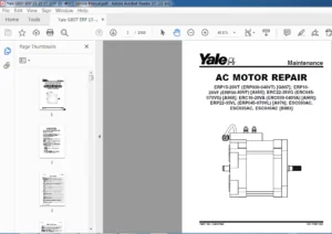
550073166-0620YRM1621-(12-2018)-US-EN 97
General 101
Special Precautions 101
Discharging the Capacitors 101
Traction Motor Repair 101
Remove 102
Disassemble 104
Clean/Inspect 108
Assemble 109
Install 110
Hydraulic Motor Repair 111
Disassemble 111
Inspect 113
Assemble 114
Special Tools 115
Tool Chart 115
Troubleshooting 116
550073167-0630YRM1609-(03-2021)-US-EN 121
Master Drive Unit 125
General 125
Description 125
Maintenance 126
Changing the Oil 126
Remove 126
Clean and Inspect 131
Install 134
Troubleshooting 135
550090222-8000YRM1634-(03-2018)-US-EN 139
550090223-8000YRM1635-(10-2013)-US-EN 157
550090441-2200YRM1631-(07-2017)-US-EN 187
General 193
Introduction 193
Description 193
Button Keypad 193
LED Indicator Lights 193
LCD Screen 194
Dash Display Menu Access 194
Menu Navigation 194
Dash Display Menu Operation 194
Nodes 194
Menu Structure 195
Service-Level Menu 196
Hour Meters 197
H1 Truck Hours 197
H2 Traction Hours 197
H3 Pump Hours 197
H5 Odometer Hours 197
H10 Display Hours 197
H32 Combinatin Node Hours 197
Performance 198
Performance Level 1 198
P1 1 Forward 199
P1 2 Reverse 199
P1 3 Acceleration 199
P1 4 Plug 199
P1 5 Coast 199
P1 6 Lift Speed 199
P1 7 Lower Speed 199
Operator Passwords 200
Add Password 200
Delete Password 200
Edit Password 200
Operator Password 200
Clear Log 201
Operator Logs 201
Operator 1-150 201
Information 202
I1 Model 202
I3 Serial Number 202
I5 Truck Voltage 202
Settings 203
S1 Metric 203
S2 User Performance 203
S3 Timeout 203
S4 Battery Type 203
S5 BDI Startup Full 203
S6 BDI Full 203
S7 BDI Empty 203
S8 BDI Reset 203
S9 Lift Interrupt 204
S10 Audible Warning 204
S11 Visual Warning 204
S12 Checklist 204
S13 Maint Reminder 204
S14 Restore Default 204
S15 Truck Lockout 204
S61 Extended Shift 205
S63 Walk Speed Accel 205
S64 Walk Speed Decel 205
S65 Pick Accel 205
S66 Pick Decel 205
S67 Min Steer Assist F 205
S68 Min Steer Assist R 205
Software Versions 205
Error Log 206
(E1) Error Log 1 207
Error 1 1 (E1 1) 207
Error 1 2 (E1 2) 207
Error 1 3 (E1 3) 207
Error 1 4 (E1 4) 207
Diagnostics 208
Diagnostics 208
D1 Status 208
D2 Input 208
D3 Output 208
D1 Status 208
D1 1 CAN 209
D1 2 Contactor 209
D1 3 Full Traction 209
D1 4 Limp Traction 209
D1 6 Lift 209
D1 7 Lower 209
D2 Inputs 210
D2 10 Display 210
D2 10 1 Bus Error 210
D2 10 2 Bus Max Error 210
D2 10 32 Combination Controller 210
D2 10 60 CTRL Hand 210
D2 32 Combination Controller 211
D2 32 1 Target Speed 213
D2 32 2 Motor Speed 213
D2 32 3 Motor Encoder 213
D2 32 4 Controller Temperature 213
D2 32 5 Motor Temperature 213
D2 32 6 Motor Current 213
D2 32 7 Cap Voltage 214
D2 32 8 Cap Maximum Voltage 214
D2 32 9 Cap Minimum Voltage 214
D2 32 10 Key Voltage 214
D2 32 11 Key Max Voltage 214
D2 32 12 Key Minimum Voltage 214
D2 32 16 MC Connct 214
D2 32 17 MC Current 214
D2 32 18 Horn Switch 214
D2 32 19 Brake Switch 214
D2 32 20 Horn Connect 214
D2 32 22 Pump Current 214
D2 32 22 Rabbit Switch 214
D2 32 26 Regen Switch 214
D2 32 27 Lift Switch 214
D2 32 28 Lower Switch 214
D2 32 31 Load Hold Connect 214
D2 32 32 Load Hold Current 215
D2 32 33 SOC 215
D2 60 Control Handle 215
D2 60 1 Horn Switch 215
D2 60 2 Lift Switch 215
D2 60 4 Lower Switch 215
D2 60 10 Tilt Up SW 215
D2 60 11 Tilt Down SW 215
D2 50 14 4th Aux IN SW 215
D2 50 15 4th Aux OUT SW 216
D2 60 19 Trac Input 216
D3 Output 216
D3 10 Display 216
D3 10 10 Display Com 216
D3 10 32 Combination Com 216
D3 10 60 Handle Com 216
D3 32 Traction 217
D3 32 1 U-V Line DC Curr 218
D3 32 2 U-W Line DC Curr 218
D3 32 3 V-W Line DC Curr 218
D3 32 6 Pump DC Current 218
D3 32 7 Pump Motor Short 218
D3 32 9 Load Hold 218
D3 32 10 Backup Alarm 218
D3 32 11 Strobe 218
D3 32 12 Horn 218
Calibration 219
219
C4 Throttle 219
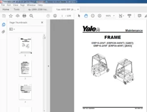
550090934-0100YRM1580-(01-2016)-US-EN 223
General 227
Description 227
Features 230
MPC060-VG and MPC080-VG
230
MTR005-F and MTR007-F
230
Covers 230
Special Precautions 230
Frame Separation and Assembly 230
MPC060-VG and MPC080-VG
230
Frame Separation 230
Painting Instructions 231
Label Replacement 231
Battery Compartment 233
550090937-1600YRM1627-(01-2016)-US-EN 237
Introduction 241
General 241
Description of Operation 241
Special Precautions 242
Control Handle 243
Remove 243
Install 246
Support Assembly 246
Remove 246
Disassemble 246
Repair 247
Assemble 247
Install 247
Control Handle and Support Assembly (Complete) 248
Remove 248
Install 248
Troubleshooting 250
550090938-1800YRM1628-(01-2016)-US-EN 253
General 257
Accessing the Drive Unit Compartment 257
Description 258
Special Precautions 259
Brake Check 260
Brake Release 260
Brake Apply 260
Air Gap 261
Hold On Grade Test 262
Brake Assembly Repair 262
MPC060-VG and MTR005-F
263
Remove 263
Repair 264
Install 264
MPC080-VG and MTR007-F
265
Remove 265
Repair 266
Install 266
Troubleshooting 266
550090939-1900YRM1629-(10-2013)-US-EN 271
550090940-2200YRM1630-(01-2016)-US-EN 299
General 303
Introduction 303
Description 303
Button Keypad 303
LED Indicator Lights 303
LCD Screen 304
Dash Display Menu Access 304
Menu Navigation 304
Dash Display Menu Operation 305
Nodes 305
Menu Structure 305
Supervisor-Level Menu 306
Hour Meters 306
H1 Truck Hours 308
H2 Traction Hours 308
H3 Pump Hours 308
H5 Odometer Hours 308
H10 Display Hours 308
H32 Combination Node Hours 308
Performance 308
Performance Level 1 309
P1 1 Forward 310
P1 2 Reverse 310
P1 3 Acceleration 310
P1 4 Plug 310
P1 5 Coast 310
P1 6 Lift Speed 310
P1 7 Lower Speed 310
Operator Passwords 310
Add Password 311
Delete Password 311
Edit Password 311
Operator Password 311
Clear Log 311
Operator Logs 311
Operator 1-150 312
Information 312
I1 Model 313
I3 Serial Number 313
I5 Truck Voltage 313
Software Versions 313
550090942-2200YRM1632-(01-2016)-US-EN 317
General 321
Description of Operation 322
Special Precautions 326
Discharging the Capacitors 326
Electrical System Checks 327
Repairs 329
Calibration Mode 329
Controller, Replace 329
Remove 329
Install 330
Control Module 331
Check 331
Remove 333
Install 334
Contactor 334
Check 334
Remove 334
Install 335
Key Switch 335
Remove 335
Install 336
Parking Brake Switch 336
Remove 336
Install 337
Fuses 337
Horn 337
Replace 337
High Speed Switch Assembly 338
Remove 338
Install 339
Control Handle 339
Disassemble 339
Hand-brake 339
Upper Cover 340
Handle Shaft 341
Lower Cover 341
Directional/Throttle Switch 341
Neutral Switches 341
Throttle Sensor 341
Assemble 345
Directional/Throttle Switch 345
Neutral Switches 345
Throttle Sensor 346
Lower Cover 346
Handle Shaft 346
Upper Cover 347
Hand-brake 347
Lift Pump Motor (MPC060-VG and MPC080-VG Only) 347
Remove 348
Install 348
Troubleshooting 348
General Troubleshooting 348
550090943-4000YRM1589-(10-2013)-US-EN 353
550090944-8000YRM1633-(10-2013)-US-EN 375
550090945-9000YRM1657-(01-2016)-US-EN 389
SECTION 9030 ELECTRICAL SYSTEM 393
Group 03 – General Maintenance and Diagnostic Data 395
Group 20 – Diagnostic Trouble Codes 405
S.V 05/24