Yale Forklift A879 (GC_GDCGLC135-155CA) Service Manual – PDF DOWNLOAD
$36.95
Yale Forklift A879 (GC_GDCGLC135-155CA) Service Manual – PDF DOWNLOAD
Description
Yale Forklift A879 (GC_GDCGLC135-155CA) Service Manual – PDF DOWNLOAD
FILE DETAILS:
Yale Forklift A879 (GC_GDCGLC135-155CA) Service Manual – PDF DOWNLOAD
Language : English
Pages : 1048
Downloadable : Yes
File Type : PDF
IMAGES PREVIEW OF THE MANUAL:
TABLE OF CONTENTS:
Yale Forklift A879 (GC_GDCGLC135-155CA) Service Manual – PDF DOWNLOAD
524150774-0600YRM0705-(03-2006)-US-EN 1
toc 1
Perkins Diesel Engines 1
Safety Precautions Maintenance and Repair 2
General 9
General Safety Rules 9
Description 10
Engine Serial Number Codes 13
Engine Data 13
Engine Removal and Installation 15
Lift Engine 15
Cylinder Head Assembly Repair 15
Valve Cover 15
Remove 15
Install 16
Rocker Arm Assembly 16
Remove 16
Install 16
Disassemble 16
Inspect 17
Assemble 17
Valve Clearance Adjustments 17
Four-Cylinder Engines 18
Six-Cylinder Engines 18
Valve Springs 18
Cylinder Head Assembly 20
Remove 20
Install 22
Valves and Valve Springs 26
Remove 26
Inspect 26
Install 27
Valve Guides 27
Inspect 27
Remove 28
Install 28
Cylinder Head and Valve Seats 28
Inspect 28
Repair 28
New Valve Seats, Install 28
Piston and Connecting Rod Assemblies Repair 30
Rod Bearings 30
Remove 31
Install 31
Piston and Connecting Rod Assembly 32
Service Note 32
Remove 32
Install 33
Piston Rings 34
Remove 34
Inspect 34
Install 34
Piston and Connecting Rod 35
Disassemble 35
Inspect 36
How to Select Correct Replacements 36
Install 37
Piston Cooling Jets 37
Remove 37
Install 38
Crankshaft Assembly Repair 38
General 38
Crankshaft Pulley 39
Engine AR, Remove 39
Engines YG and YH, Remove 39
Inspect 40
Engine AR, Install 40
Engines YG and YH, Install 40
Rear Oil Seal 41
Replace 41
Main Bearings 42
Remove 42
Inspect 43
Install 43
Thrust Washers 43
Crankshaft Axial Movement, Check 43
Remove 44
Install 44
Crankshaft 45
Remove 45
Inspect 45
Install 45
Flywheel 47
Remove 47
Ring Gear, Replace 47
Install 47
Flywheel Housing 48
Remove 48
Install 48
Timing Case and Timing Gears Repair 49
General 49
Timing Case Cover 49
Remove 49
Install 50
Front Oil Seal 50
Remove 50
Install 50
Crankshaft Pulley Wear Sleeve 51
Install 51
Idler Gear and Hub 51
Remove 51
Install 52
Air Compressor Drive, Bendix 53
Disassemble 53
Assemble 54
Fuel Injection Pump Gear 54
Remove 55
Install 55
Camshaft Gear 56
Remove 56
Install 56
Crankshaft Gear 57
Remove 57
Install 57
Timing Case 57
Remove 57
Install 58
Camshaft and Tappets 59
Remove 59
Install 59
Cylinder Block Assembly Repair 60
Description 60
Cylinder Block 60
Disassemble 60
Inspect 61
Assemble 61
Cylinder Bore (Four-Cylinder Engines) 61
Cylinder Liner (Six-Cylinder Engines) 62
Inspect 62
Cylinder Liner Condition, Check 62
Remove 63
Service Liner, Install 63
Partially Finished Liner, Install 65
Engine Timing 65
Description 65
How to Set Number One Piston to TDC on Compression Stroke 67
How to Set Number One Piston to TDC on Compression Stroke (Alter 67
Valve Timing, Check 68
Fuel Injection Pump Timing, Check 69
Turbocharger – Engine YH Repair 70
General 70
Remove 70
Install 70
Impeller and Compressor Housing, Clean 71
Lubrication System Repair 72
General 72
Oil Filter, Replace 72
Filter Head 72
Remove and Install 72
Oil Sump 73
Remove 73
Install 73
Oil Pump 73
Remove 73
Inspect 74
Install 75
Relief Valve 75
Remove 75
Disassemble 76
Inspect 76
Assemble 76
Install 76
Idler Gear Shaft, Replace 77
Remove 77
Remove (Alternative) 77
Install 78
Install (Alternative) 78
Install (Alternative for Four-Cylinder Engines Only) 79
Fuel System Repair 79
Description 79
Fuel Injection Pump 80
Remove 80
Install 81
Check and Adjust 81
Fuel System Air Removal 82
Fuel Filter, Replace 83
Canister Type 83
Quick Release Canister Type 84
Fuel Injectors 85
Remove 85
Inspect 85
Install 85
Fuel Pump 86
Remove 86
Disassemble 86
Assemble 87
Install 88
Test 88
Cooling System Repair 88
General 88
Thermostat 88
Remove 88
Install 89
Test 89
Coolant Pump 89
Remove 89
Disassemble 90
Assemble 91
Install 94
Fan and Fan Drive 94
Remove 94
Install 95
Oil Cooler (Six-Cylinder Engines) 95
Remove 95
Disassemble and Assemble 95
Install 96
Oil Cooler Bypass Valve 96
Electrical Equipment Repair 96
Drive Belts 96
Adjustment 96
Remove 97
Install 97
Alternator 97
Remove 97
Install 97
Starter Motor 98
Remove 98
Install 98
Cold Start Aid 98
Air Compressor – Engines YG and YH 98
General 98
Repair 98
Remove 98
Install 99
Rotary Exhauster Replacement 100
Remove 100
Clean 100
Install 100
Engine Specifications 101
Cylinder Head Assembly 101
Piston and Connecting Rods 104
Crankshaft Assembly 107
Crankshaft Overhaul 108
Timing Case and Drive Assembly 110
Engine Block Assembly 111
Turbocharger 114
Lubrication System 114
Fuel System 115
Cooling System 117
Flywheel and Housing 117
Electrical Equipment 118
Torque Specifications 118
Cylinder Head Assembly 118
Piston and Connecting Rod Assemblies 118
Crankshaft Assembly 118
Timing Case and Drive Assembly 119
Turbocharger 119
Lubrication System 119
Fuel System 119
Cooling System 119
Flywheel 119
Auxiliary Equipment 119
Special Torque Specifications 120
Flywheel and Housing 120
Turbocharger 120
Electrical Equipment 120
Auxiliary Equipment 120
Special Tools* 121
Troubleshooting 126
tables 1
Table 1 Cylinder Head 101
Table 2 Valve Guides 101
Table 3 Inlet Valves 101
Table 4 Exhaust Valves 102
Table 5 Valve Springs 104
Table 6 Tappets 104
Table 7 Rocker Arm Shaft 104
Table 8 Rocker Arms and Bushings 104
Table 9 Pistons (Engine AR) 104
Table 10 Pistons (Engines YG and YH) 104
Table 11 Piston Rings (Engine AR) 105
Table 12 Piston Rings (Engines YG and YH) 105
Table 13 Piston Pins 106
Table 14 Connecting Rods 106
Table 15 Small End Bushings 106
Table 16 Connecting Rod Bearings (Engines AR and YG) 106
Table 17 Connecting Rod Bearings (Engine YH) 106
Table 18 Piston Cooling Jets 107
Table 19 Crankshaft 107
Table 20 Main Bearings 107
Table 21 Crankshaft Thrust Washers 107
Table 22 Crankshaft Heat Treatment 108
Table 23 Crankshaft Overhaul Specifications 108
Table 24 Maximum Variation (Run-out) 110
Table 25 Camshaft 110
Table 26 Camshaft Thrust Washer 110
Table 27 Camshaft Gear 110
Table 28 Gear for Fuel Injection Pump 111
Table 29 Crankshaft Gear 111
Table 30 Idler Gear and Hub 111
Table 31 Cylinder Block (Engine AR) 111
Table 32 Cylinder Bore Specifications 112
Table 33 Cylinder Block (Engines YG and YH) 113
Table 34 Cylinder Liners (Engines YG and YH) 113
Table 35 Cylinder Liner Specifications (Partially Finished) 113
Table 36 Oil Pump (Engine AR) 114
Table 37 Oil Pump (Engines YG and YH) 114
Table 38 Idler Gear for Oil Pump 114
Table 39 Relief Valve 115
Table 40 Oil Filter 115
Table 41 Lucas Fuel Injection Pump 115
Table 42 Fuel Injector Codes 116
Table 43 Fuel Pump (Engine AR) 117
Table 44 Fuel Pump (Engines YG and YH) 117
Table 45 Fuel Filter 117
Table 46 Coolant Pump 117
Table 47 Thermostat 117
Table 48 Fan Drive Housing 117
Table 49 Limits for Flywheel Run Out and Alignment (Total Indic 117
Table 50 Alternator 118
Table 51 Starter Motor 118
Table 52 Cold Start Aid 118
Table 53 List of Possible Causes 126
524150775-0700YRM0626-(03-2003)-US-EN 131
toc 131
Cooling System 131
Safety Precautions Maintenance and Repair 132
General 135
Description 136
Radiator 136
Radiator Cap 136
Thermostat 136
Water Pump 137
Fan and Fan Shroud 137
Cooling System Checks 137
Radiator 137
Thermostat 137
Water Pump 138
Exhaust Leaks 138
Fan and Fan Shroud 138
Radiator Cleaning 138
Drain 138
Clean 138
Fill 139
Troubleshooting 140
524150779-1400YRM0046-(08-2012)-US-EN 143
toc 143
Differential 143
Safety Precautions Maintenance and Repair 144
General 147
Description 147
Differential Repair 147
Remove 147
Differential Carrier From Axle Housing, Remove 147
Differential and Ring Gear From Differential Carrier, Remove 151
Drive Pinion and Pinion Carrier From Differential Carrier, Remov 153
Disassemble 154
Differential and Ring Gear Assembly, Disassemble 154
Drive Pinion and Pinion Carrier, Disassemble 155
Clean and Inspect 158
Assemble 159
Pinion, Bearings, and Pinion Carrier, Assemble 159
Pinion Bearings, Adjust Preload 159
Press Method 159
Yoke or Flange Method 160
Triple-Lip Seal, Install 161
Pinion Carrier Shim Set, Adjust Thickness (Depth of Pinion) 162
Differential and Ring Gear, Assemble 164
Differential Gears Rotating Torque, Check 166
Differential and Ring Gear Assembly, Install 167
Differential Bearings, Preload Adjust 168
Ring Gear, Runout Check 169
Ring Gear Backlash, Adjust 170
Gear Set, Tooth Contact Pattern Check 172
Thrust Screw, Install and Adjust 175
Install 175
Differential Assembly Into Axle Housing, Install 175
Specifications 176
Troubleshooting 180
tables 143
Table 1 Ring Gear Backlash Adjustment Specifications 171
Table 2 Ring and Pinion Tooth Contact Adjustment 172
Table 3 General Specifications 176
Table 4 Rivet Installation Pressure 176
Table 5 Pinion Adjustment 176
Table 6 Pinion Preload Pressure 177
Table 7 Torque Specifications 178
Table 8 Torque Specifications for Metric Hardware 179
Table 9 Torque Specifications for Metric (Fine) Hardware 179
524150790-2100YRM0103-(03-2007)-US-EN 183
toc 183
Tilt Cylinders 183
Safety Precautions Maintenance and Repair 184
General 187
Description 187
Tilt Cylinder Repair 187
Remove 187
Disassemble 187
Clean 187
Assemble 188
Tilt Cylinders With O-Ring or Single-Lip Seals 188
Tilt Cylinders 189
Install 190
Tilt Cylinder Leak Check 192
Tilt Cylinder Stroke and Mast Tilt Angle Adjustment 193
Torque Specifications 193
Piston Rod Nut 193
Retainer 193
Troubleshooting 194
tables 183
Table 1 Movement Rates (Maximum) for Tilt Cylinders 192
524150792-2200YRM0106-(01-2016)-US-EN 199
General 203
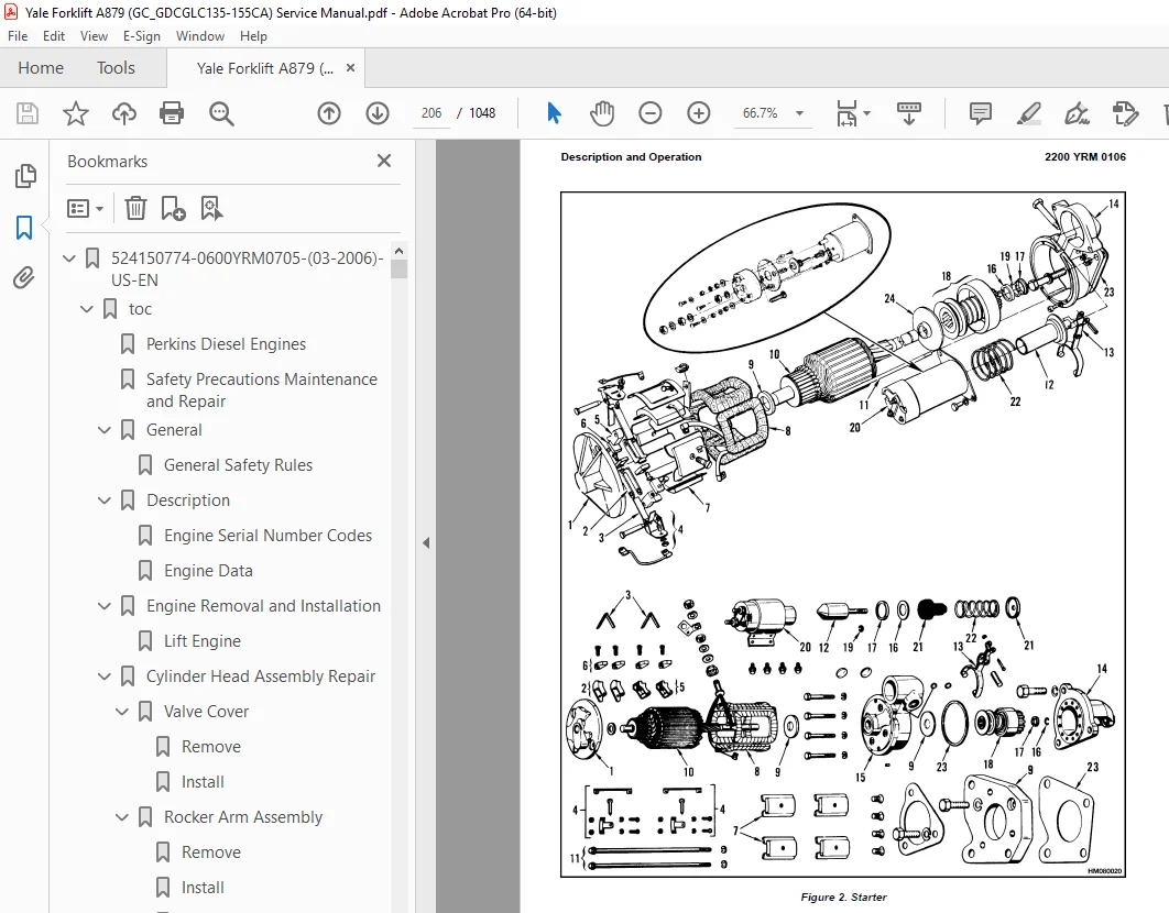
Description and Operation 204
Starter Repair 208
Remove 208
Disassemble 208
Clean 209
Assemble 209
Install 210
General Checks and Adjustments 210
Troubleshooting 212
524150794-4000YRM0135-(03-2011)-US-EN 219
toc 219
Lift Cylinders 219
Safety Precautions Maintenance and Repair 220
Safety Procedures When Working Near Mast 223
General 227
Description 227
Lowering Control Valve 227
Cylinders (General) 230
Lift Cylinder Repair 230
Lift Cylinder Removal Without Removing Mast 230
Standard Masts With Main Lift Cylinder Fastened to Crossmember o 230
Standard and Full Free-Lift Masts With Lift Cylinder Fastened to 231
Masts That Have Two Cylinders, Main Lift Cylinder and Free-Lift 232
Disassemble 232
Assemble 232
Lift Cylinder Installation in Mast 234
Standard Masts With Main Lift Cylinder Fastened to Crossmember o 234
Standard and Full Free-Lift Masts With Lift Cylinder Fastened to 234
Chevron-Style Packing 235
Chevron-Style Packing Installation on Piston 235
Chevron-Style Packing Installation in Packing Gland 237
Lift Cylinders for HI VIS® Masts 239
Description 239
Lowering Control Valve 239
Remove 241
Disassemble 242
Assemble 242
Install 244
Main Lift Cylinders 244
Free-Lift Cylinder 244
Lift System Leak Check 244
Specifications 245
Troubleshooting 246
tables 219
Table 1 Cylinder Retainer Torque Specifications and Weight Guid 245
524150797-8000YRM0231-(03-2020)-US-EN 251
General 255
Threaded Fasteners 255
Nomenclature, Threads 255
Strength Identification 256
Cotter (Split) Pins 257
Fastener Torque Tables 262
Conversion Table 264
524153897-0600YRM0590-(04-2014)-US-EN 271
524153900-0900YRM0348-(03-2003)-US-EN 323
toc 323
LPG Fuel System 323
Safety Precautions Maintenance and Repair 324
General 327
Description and Operation 328
Fuel Tank 328
Fuel Filter and Fuel Valve Unit 329
Vaporizer 330
Carburetor 331
Governor 333
LPG Tank Repair 334
Remove 334
LPG Tanks With Fixed Mounting Bracket 334
LPG Tanks With EZ Lift Mounting Bracket 334
Install 335
LPG Tanks With Fixed Mounting Bracket 335
Hydrostatic Relief Valve Repair 336
Remove and Install 336
Filter Unit Repair 337
Fuel Filter Element, Replace 337
Diaphragm and Fuel Valve, Replace 337
Hoses Replacement 339
Vaporizer Repair 339
Remove 339
Disassemble 339
Clean 339
Inspect 339
Assemble 341
Install 344
Carburetor Repair 345
Remove 345
Disassemble 345
Clean 345
Assemble 345
Install 345
Governor Repair 346
Filter Unit Check 348
Vaporizer Check 348
Pressure Reducer Valve 348
Vapor Valve 348
Carburetor Adjustment 348
Idle Mixture 348
Idle Speed 348
Power Mixture 348
Throttle Linkage Adjustment 349
Adjustment For Models GDP60-70CA (GP/GLP/GDP135-155CA), GC/GLC07 349
Adjustment For Models GC070-120LJ/MJ 349
Troubleshooting 350
524153907-1900YRM0097-(05-2012)-US-EN 357
toc 357
Hydraulic Gear Pumps 357
Safety Precautions Maintenance and Repair 358
Description 361
Operation 362
Flow Control Valve 362
Relief Valve 362
Hydraulic Gear Pump Repair 363
Remove 363
Disassemble 364
Clean 364
Inspect 365
Assemble 368
Install 370
Pump Output Check 370
Method No 1 370
Method No 2 371
Hydraulic System Air Check 372
Troubleshooting 373
524153908-1900YRM0339-(10-2003)-US-EN 379
toc 379
Hydraulic Pump Drive Assembly 379
Safety Precautions Maintenance and Repair 380
General 383
Description 383
Hydraulic Pump Drive Assembly Repair 384
Remove and Disassemble 384
Clean 385
Inspect 385
Assemble and Install 385
Troubleshooting 386
524153914-2200YRM0107-(03-2008)-US-EN 389
toc 389
High Energy Ignition (HEI) System 389
Safety Precautions Maintenance and Repair 390
Description 393
Distributor Repair 395
Remove 395
Disassemble 395
Assemble 401
Install, If Crankshaft WAS NOT Rotated when Distributor was Remo 402
Install, If Crankshaft WAS Rotated when Distributor was Removed 402
Ignition Coil Replacement 404
Some Four- and Six-Cylinder Models 404
Remove 404
Install 404
V8, Some Four- and Six-Cylinder Models 405
Remove 405
Install 405
Electronic Module Replacement 406
Remove 406
Install 406
Sensing Coil Replacement 408
Remove 408
Install 408
Spark Plugs Replacement 408
Remove 408
Install 409
Visual Check 409
High Voltage Wires Check 409
Ignition Coil Check 410
Coil in Distributor Cap Design 410
Separate Coil Design 410
Sensing Coil, Check 411
Electronic Module Check 411
Ignition Timing Adjustment 412
GM V8-366 (6-liter) Ignition System Check 413
GM V6-LPG (4 3 liter) GM V6-LPG (4 3 liter) Ignition Timing and 413
Specifications 413
Troubleshooting 414
524153916-2200YRM0765-(03-2003)-US-EN 419
toc 419
Microprocessor Spark Timing System (MSTS) 419
Safety Precautions Maintenance and Repair 420
General 423
Description 424
What MSTS Does 424
How MSTS Begins Operation 424
Operation 425
Distributor 425
Ignition Coil 426
Ignition Module 426
When Engine Is Being Started 426
When Engine Is Running 428
Manifold Absolute Pressure (MAP) Sensor 429
Engine Coolant Temperature (ECT) Sensor 429
MSTS Module Corrections 430
Troubleshooting 431
General 431
Tools and Test Equipment 433
MSTS 434
Troubleshooting Procedure 434
Where to Start 434
Visual/Physical Inspection 434
Knowledge/Tools Required 434
Damage From Static Discharge (Static Electricity) 435
Troubleshooting Information 435
Malfunction Indicator Lamp (MIL) 435
Connecting CodeMate Tester 435
Reading Diagnostic Trouble Codes (DTC) 436
Clearing Diagnostic Trouble Codes (DTC’s) 437
On-Board Diagnostic (OBD) System Check 437
Test Description 437
No Malfunction Indicator Lamp 439
Circuit Description 439
Test Description 439
No DTC-12, Malfunction Indicator Lamp ON 441
Circuit Description 441
Test Description 441
Starter Rotates Engine, Engine Does Not Run 442
Test Description 442
DTC-14 Engine Coolant Temperature (ECT) (Low Temperature Indicat 446
Circuit Description 446
Test Description 446
DTC-15 Engine Coolant Temperature Sensor (ECT) (High Temperature 448
Circuit Description 448
Test Description 448
DTC-34 Manifold Absolute Pressure (MAP) Sensor 450
Circuit Description 450
Test Description 450
DTC-41 Electronic Spark Timing (EST) Open Circuit 453
Circuit Description 453
Test Description 453
DTC-42 Electronic Spark Timing (EST) Grounded Circuit 455
Circuit Description 455
Test Description 455
DTC-51 MSTS Failure 457
Circuit Description 457
Distributor Repair 457
Remove 457
Disassemble 458
Inspect 458
Assemble 458
Install 459
Ignition Timing 459
Ignition Module Repair 460
Test For Fault 460
Replace 460
Sensing Coil Repair 461
Test For Fault 461
Replace 461
Ignition Coil Repair 462
Test For Fault 462
Remove 462
Install 462
MSTS Module Repair 463
Remove 463
Install 463
ECT Sensor Replacement 463
MAP Sensor Replacement 464
tables 419
Table 1 MSTS Module Connections 432
Table 2 Pressure Conversion Chart 433
Table 3 MSTS Diagnostic Codes 435
524153917-2200YRM0781-(03-2003)-US-EN 467
toc 467
Electronic Engine Control 467
Safety Precautions Maintenance and Repair 468
General 471
Description and Operation 471
General 471
Electronic Control Module (ECM) 471
Diagnostic Connector 471
How ECM Begins Operation 475
Electronic Engine Control 476
What ECM Does 476
Distributor 478
Ignition Module 478
When Engine Is Being Started 479
When Engine Is Running 480
Electronic Control Module (ECM) with Ignition Module Distributor 480
Fuel Control 481
Throttle Body Injection (TBI) 482
Fuel Injectors 482
Fuel Pressure Regulator 482
Throttle Position Sensor (TPS) 483
Idle Air Control (IAC) 483
GM 4 3L Engine Governor System 484
GM 3 0L Engine Governor System 484
Vacuum Ports 486
Fuel Pump 486
ECM Sensors and Controllers 488
Manifold Absolute Pressure (MAP) 488
Engine Coolant Temperature (ECT) Sensor 488
524153918-2200YRM0782-(03-2003)-US-EN 491
toc 491
Electronic Engine Control 491
Safety Precautions Maintenance and Repair 492
General 497
Troubleshooting Procedure 497
How This Section Is Arranged 497
Where Do I Start? 497
Visual/Physical Inspection 497
Knowledge/Tools Required 497
Damage From Static Discharge (Static Electricity) 497
Troubleshooting Information 498
Malfunction Indicator Lamp (MIL) 498
Reading Diagnostic Trouble Codes (DTC) 498
Clearing Diagnostic Trouble Codes (DTCs) 502
ECM Diagnostic Codes Available 503
Diagnostic Mode 503
Field Service Mode 503
ECM Learning Ability 503
SCAN Tool Information 504
On-Board Diagnostic (OBD) System Check 505
Test Description 505
Troubleshooting Charts 507
General 507
Tools and Test Equipment 507
Troubleshooting Chart Description Summary 508
A-1 – No Malfunction Indicator Lamp 508
Circuit Description 508
Test Description 509
Other Troubleshooting Checks 509
A-2 – No Scan Data, No DTC 12, Malfunction Indicator Lamp ON 511
Circuit Description 511
Test Description 511
A-3 – Starter Rotates Engine, Engine Will Not Run 513
Circuit Description 513
Test Description 513
Other Troubleshooting Checks 513
A-4 – Fuel Injector Circuit 515
Test Description 515
A-5 – Fuel Pump Relay Circuit 517
Circuit Description 517
Test Description 517
Other Troubleshooting Checks 517
A-6 – Fuel System Troubleshooting 519
Circuit Description 519
Test Description 519
Other Troubleshooting Checks 519
Test Description 521
Fuel Pressure Check 523
A-7 – Ignition System Troubleshooting 523
Test Description 524
DTC 14 Engine Coolant Temperature Sensor Circuit (Low Temperatur 527
Circuit Description 527
Test Description 527
Other Troubleshooting Checks 527
DTC 15 Engine Coolant Temperature Sensor Circuit (High Temperatu 529
Circuit Description 529
Test Description 529
Other Troubleshooting Checks 529
DTC 21 Throttle Position Sensor Circuit (Signal Voltage High) 531
Circuit Description 531
Test Description 531
Other Troubleshooting Checks 531
DTC 22 Throttle Position Sensor Circuit (Signal Voltage Low) 533
Circuit Description 533
Test Description 533
Other Troubleshooting Checks 533
DTC 31 Engine Governor Circuit 535
Circuit Description 535
Test Description 535
Other Troubleshooting Checks 535
DTC 33 Manifold Absolute Pressure (MAP) Sensor Circuit (Signal V 537
Circuit Description 537
Test Description 537
Other Troubleshooting Checks 537
DTC 34 Manifold Absolute Pressure (MAP) Sensor Circuit (Signal V 539
Circuit Description 539
Test Description 539
Other Troubleshooting Checks 539
DTC 41 Electronic Spark Timing (EST) – Open EST Circuit 541
Circuit Description 541
Test Description 541
Other Troubleshooting Checks 541
DTC 42 EST – Grounded EST Circuit, Open or Grounded Bypass Circu 543
Circuit Description 543
Test Description 544
Other Troubleshooting Checks 544
DTC 51 ECM Failure 546
Circuit Description 546
Other Troubleshooting Checks 546
Troubleshooting, Poor Operation 547
General 547
Make a Careful Visual Check 547
FAULT: Codes or Performance That Is Not Regular 547
FAULT: Loss of Diagnostic Trouble Code (DTC) Memory 547
FAULT: Engine Quits While Driving 547
Additional Checks 547
FAULT: Engine Is Difficult to Start 547
FAULT: Variation in Engine Power When Throttle Is Held Steady 548
FAULT: Decreased Engine Power 548
FAULT: Detonation 549
FAULT: Engine Momentarily Does Not Increase Power When Throttle 549
FAULT: One or More Cylinders Do Not Operate Correctly – Engine D 550
FAULT: Rough Idle or Engine Stalls During Idle 550
FAULT: Fuel Usage Too High 550
FAULT: Dieseling 551
FAULT: Backfire 551
System Test Charts 551
General 551
Engine Coolant Temperature (ECT) Sensor Test 551
Throttle Position (TP) Sensor Check 552
Minimum Idle Speed 552
Adjustment 553
B-1 – Idle Air Control (IAC) System Check 554
Circuit Description 554
Other Troubleshooting Checks 554
B-2 – Manifold Absolute Pressure (MAP) Sensor Output Test 556
Circuit Description 556
Test Description 556
B-3 – Check Governor System 558
Governor System Not Operating Correctly 558
Check Function of Governor System 558
Check PCV System 559
Fuel System Components Repair 559
General 559
Fuel Pressure Relief Procedure 559
Fuel Pump Replacement 559
Throttle Body Injection Unit (TBI) 560
Remove 560
Clean and Inspect 561
Install 561
Fuel Meter Body 561
Remove 561
Install 564
Fuel Injector 564
Remove 564
Install 565
Pressure Regulator 565
Remove 565
Inspect 565
Install 565
Throttle Position Sensor (TPS) 566
Remove 566
Install 566
Idle Air Control (IAC) Valve 566
Remove 566
Clean and Inspect 566
Install 567
Governor System 3 0L Engine Repair 567
Governor Module, Replace 567
Governor Motor, Replace 567
Throttle Cables, Install and Adjust 567
Foot Directional Control Pedal, Check 568
Governor System 4 3L Engine Repair 569
Governor Throttle Drive Assembly 569
Remove 569
Inspect 570
Install 570
Governor Drive Motor 570
Remove 570
Clean and Lubricate 570
Install 571
Inspect 572
Ignition System Components Repair 572
ECM Replacement 572
Function Check 572
Distributor 572
Remove 572
Disassemble 572
Inspect 573
Assemble 573
Install 573
Firing Order 574
Ignition Timing 574
Ignition Module Repair 574
Test For Fault 574
Replace 575
Sensing Coil 575
Test 575
Replace 576
Ignition Coil 576
Test 576
Remove 576
Install 577
Sensors Repair 577
Engine Coolant Temperature (ECT) Sensor, Replace 577
MAP Sensor, Replace 577
PCV System Repair 578
Replace 578
Wiring 578
Connectors and Terminals 578
Procedures for Spark Plugs, Spark Plug Wires, and Boots 581
Wiring Diagram 581
Spark Plugs Troubleshooting 586
Special Tools 587
tables 491
Table 1 ECM Diagnostic Codes Available 503
Table 2 SCAN Tool Information 504
Table 3 Troubleshooting Chart Description Summary 508
Table 4 ECT Sensor – Temperature vs Resistance 529
Table 5 ECT Sensor – Temperature vs Resistance 552
Table 6 ECM Connector J1 Identification 584
Table 7 ECM Connector J2 Identification 585
524185156-1300YRM0324-(10-2003)-US-EN 591
toc 591
Two-Speed Powershift Transmission 591
Safety Precautions Maintenance and Repair 592
General 595
Mechanical Description 595
Torque Converter 595
Transmission Pump 596
Shaft Assemblies 596
Input Shaft 597
Forward Clutch Shaft 597
Clutch Assemblies 597
Countershaft 604
Output Shaft 604
Hydraulic Operation 605
Torque Converter 605
Seal Rings 606
Control Valve 606
System Pressure Regulator 609
Clutch Pressure Regulator 609
Torque Converter Regulator 610
Inching Spool 610
Direction Spool, Direction Control Lever 610
Direction Spool, Foot Directional Control Pedal 611
Range Spool 612
Drain Spool 612
Accumulator 612
Modulator Spool 612
Operation 613
Lubrication Circuit 613
Foot Directional Control Pedal 614
Oil Flow Diagrams 615
Neutral 615
Forward-Low 615
Forward-Low-Inching 615
Reverse-Low 616
524185157-1300YRM0325-(10-2003)-US-EN 623
toc 623
Two-Speed Powershift Transmission 623
Safety Precautions Maintenance and Repair 624
General 627
Transmission Repair 627
Transmission and Torque Converter, Remove 627
Transmission, Disassemble 629
Reverse-Low Clutch, Disassemble 632
Reverse-High Clutch, Disassemble 635
Forward-Low Clutch, Disassemble 638
Forward-High Clutch, Disassemble 641
Clean and Inspect 643
Forward Low and High Clutches Assembly 644
Forward Clutches, Assemble 646
Reverse-Low Clutch, Assemble 652
Reverse Clutches, Assemble 654
Transmission, Assemble 661
Torque Converter, Install 667
Control Valve Repair 668
Remove 668
Disassemble 669
Assemble 670
Install 672
Foot Directional Control Pedal 672
Remove and Disassemble 672
Assemble and Install 672
Stall Test 675
Linkage Adjustments 676
Linkage for Inching Pedal GDP60-70CA (GP/GLP/GDP135-155CA) (A878 676
Linkage for Inching Pedal GC/GLC/GDC135-155CA (A879, B879) 679
Linkage for Range Lever – Early Model GDP60-70CA (GP/GLP/GDP135- 681
Linkage for Direction Control Lever – Early Model GDP60-70CA (GP 683
Linkage for Range Lever – Later Model GDP60-70CA (GP\GLP\GDP135- 683
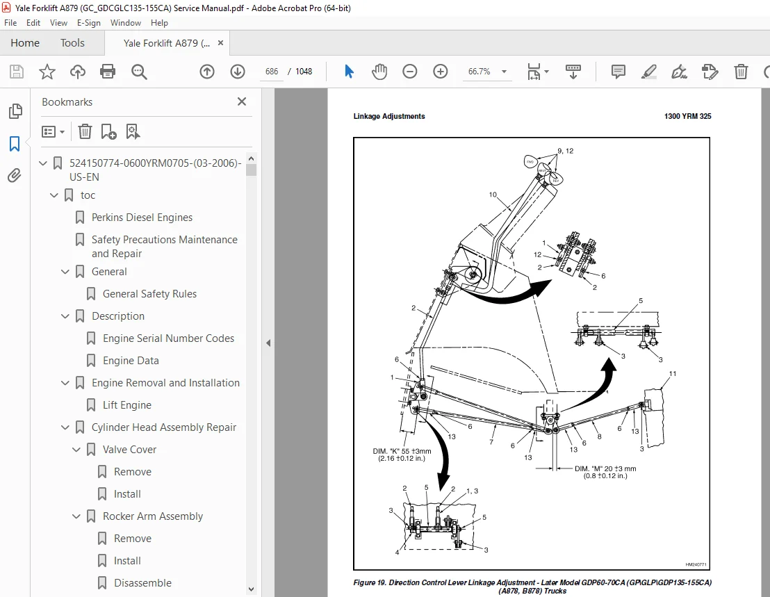
Linkage for Direction Control Lever – Later Model GDP60-70CA (GP 685
Linkage for Range Lever GC/GLC/GDC135-155CA (A879, B879) 687
Linkage for Direction Control Lever GC/GLC/GDC135-155CA (A879, B 687
Oil Pressure Check 689
System Pressure Check Port 690
Torque Converter Check Port 690
Clutch Pressure Check Port 690
Inching Pressure 690
Solenoid Check Ports ( Foot Directional Control Only) 690
Lubrication Pressure Check Ports 690
Specifications 690
Troubleshooting 691
Correct System Pressure: 1300 ±124 kPa ( 189 ±18 psi) 693
Correct Clutch Pressure: 924 ±69 kPa ( 134 ±10 psi) 694
Correct Solenoid Pressure (Foot Directional Control Only): 965 ± 695
Torque Converter Pressure: 834 ±69 kPa ( 121 ±10 psi) 695
Lubrication Pressure: 83 ±21 kPa ( 12 ±3 psi) 696
tables 623
Table 1 Stall Speed Specifications 675
524185160-1600YRM0054-(10-2003)-US-EN 699
toc 699
Steering Control Unit 699
Safety Precautions Maintenance and Repair 700
General 703
Description 703
Operation 703
Steering Wheel and Column Assembly Repair 705
Steering Column Assembly Repair 705
Type A Steering Column Assembly 705
Remove and Disassemble 705
Assemble and Install 707
Type B Steering Column Assembly 709
Remove and Disassemble 709
Assemble and Install 709
Steering Control Unit 712
Disassemble 712
Clean 715
Assemble 716
System Air Removal 721
Troubleshooting 721
524185164-2000YRM0090-(10-2003)-US-EN 725
toc 725
Main Control Valve 725
Safety Precautions Maintenance and Repair 726
General 729
Description 729
Operation 729
Lift Spool 729
Tilt Spool 729
Tilt Backward 729
Tilt Forward 733
Two-Stage Relief Valve 734
Main Control Valve Repair 735
Remove and Disassemble 735
Clean and Inspect 735
Assemble 735
Install 736
Two-Stage Relief Valve 736
Troubleshooting 737
tables 725
Table 1 Relief Pressures (Oil temperature at 55 to 66 C ( 131 t 736
524185165-2200YRM0143-(02-2007)-US-EN 741
toc 741
Instrument Panel Indicators and Senders 741
Safety Precautions Maintenance and Repair 742
General 745
Description 746
Internal Combustion Engine Trucks 746
Instrument Cluster Panels at Base of Steering Column, Descriptio 751
Trucks With Instrument Cluster Display Panels, Description 752
Electric Lift Trucks 755
Battery Gauge With Lift Interrupt (Curtis 933/1 and 933/4 Models 756
Battery Gauge With Lift Interrupt and Brush Wear Indicator (GE), 756
EV-100LX Motor Controller Display Panel (ITW), Description 757
Adjustments – General 758
Replacement – General Information 758
Internal Combustion Engine Display Panel Replacement 758
Display Panels Mounted at Base of Steering Column 758
Remove 758
Install 760
Instrument Cluster Display Panels Mounted on Cowl 760
Remove and Install 760
Inner Components, Replace 760
Electric Truck Display Panel Replacement 762
GE and Curtis 933/1 and 933/4 Battery Gauges 762
Controller for Battery Indicator, Replace 762
ITW Display Panel, Replace 762
Remove 762
Sender Replacement 766
Fuel Level Sender 766
Pressure and Temperature Sender 766
Seat Sensor, Operator Presence System (OPS) 767
Remove 767
Install 767
Operator Presence System Module Replacement 767
Remove 767
Install 769
Specifications 770
Meter Specifications 770
Sender Specifications 771
Troubleshooting 772
Meter 772
Troubleshooting for Operator Presence System 773
tables 741
Table 1 Troubleshooting Procedure for Operator Presence Module 773
524185167-4000YRM0329-(09-2010)-US-EN 779
toc 779
Masts 779
Safety Precautions Maintenance and Repair 780
General 783
Description and Operation 783
General 783
Safety Procedures When Working Near Mast 784
Two-Stage Mast 786
Three-Stage Mast 787
Carriage Repair 788
Remove 788
Sideshift Carriage, Disassemble 790
Sideshift Carriage, Assemble 792
Install 792
Two-Stage Mast Repair 793
Remove 793
Disassemble 795
Clean and Inspect 795
Assemble 796
Install 797
Three-Stage Mast Repair 798
Remove 798
Disassemble 798
Clean and Inspect 799
Assemble 799
Install 800
Mast Operation Check 801
Lift and Tilt System Leaks Check 801
Lift System 801
Tilt System 802
Tilt Cylinder Stroke and Backward Tilt Angle Adjustment 802
Lift Chain Adjustments 803
Mast Adjustments 805
Carriage Adjustment 807
Troubleshooting 808
tables 779
Table 1 Mast Parts Weight 793
Table 2 Hook-Type Carriage Chain Adjustment 804
Table 3 Pin-Type Carriage Chain Adjustment 804
524185171-8000YRM0519-(06-2007)-US-EN 813
toc 813
Diagrams 813
Safety Precautions Maintenance and Repair 814
524192611-0100YRM0449-(02-2007)-US-EN 891
toc 891
Frame 891
Safety Precautions Maintenance and Repair 892
General 895
Description 895
Counterweight Repair 896
Remove 896
Install 897
Hood Repair 897
Remove 897
Install 897
Overhead Guard Repair 898
Remove 898
Install 898
Operator Restraint System Repair 899
Automatic Locking Retractor (ALR) 899
Emergency Locking Retractor (ELR) 899
Fuel and Hydraulic Tanks Repair 900
Inspect 900
Small Leaks, Repair 900
Large Leaks, Repair 900
Clean 900
Steam Method of Cleaning 901
Chemical Solution Method of Cleaning 901
Additional Preparations for Repair 901
Radiator Repair 901
Remove 901
Install 902
Exhaust System Repair 902
Muffler 902
Remove 902
Install 902
Engine Repair 906
Remove 906
Install 906
Throttle Pedal Adjustment 908
Perkins 1104C-44(RE) Diesel Engine 908
Safety Labels 910
524192612-1400YRM0450-(09-2003)-US-EN 915
toc 915
Drive Axle 915
Safety Precautions Maintenance and Repair 916
General 919
Description 919
Drive Axle Repair 920
Remove 920
Units With Manual Transmission 920
Units With Powershift Transmission 920
Disassemble 920
Clean 921
Inspect 921
Assemble 922
Install 922
Units With Manual Transmission 922
Units With Powershift Transmission 923
Torque Specifications 923
Troubleshooting 924
524192613-1600YRM0451-(09-2003)-US-EN 927
toc 927
Steering Axle 927
Safety Precautions Maintenance and Repair 928
General 931
Description 931
Steering Axle Assembly Repair 932
Remove 932
Install 932
Wheels and Hubs Repair 933
Remove and Disassemble 933
Clean 933
Assemble and Install 933
Spindles, Bearings, and Tie Rods Repair 933
Remove 933
Clean 934
Assemble and Install 934
Steering Cylinder Repair 935
Remove and Disassemble 935
Clean and Inspect 935
Assemble and Install 936
Troubleshooting 936
524192614-1800YRM0452-(02-2004)-US-EN 941
toc 941
Brake System 941
Safety Precautions Maintenance and Repair 942
General 945
Description and Operation 945
Brake Booster and Master Cylinder 945
Service Brake Assembly 947
Parking Brake 947
Brake Shoe Assemblies Repair 948
Remove and Disassemble 948
Clean 949
Inspect 949
Assemble and Install 949
Master Cylinder Repair 950
Remove 950
Disassemble 950
Clean and Inspect 951
Assemble 951
Install 951
Brake Booster Repair 952
Remove 952
Disassemble 952
Clean and Inspect 952
Assemble 952
Install 953
Brake System Air Removal 954
Brake Pedal Adjustment 954
Brake Shoes Adjustment 955
Parking Brake Adjustment 955
Brake Booster Relief Valve Check 955
Troubleshooting 956
524192615-1900YRM0453-(09-2003)-US-EN 961
toc 961
Hydraulic System 961
Safety Precautions Maintenance and Repair 962
General 965
Description and Operation 965
Main Hydraulic Pump 965
Steering Pump 965
Main Control Valve 965
Control Valve Lever 969
Filter 969
Steering Control Unit 969
Brake Booster 969
Main Hydraulic Pump Repair 970
Remove 970
Disassemble 970
Clean and Inspect 970
Assemble 971
Install 971
Specifications 971
Hydraulic System 971
Hydraulic Tank 971
Hydraulic Oil 971
Relief Pressures* 971
Hydraulic Pump 971
Steering Pump 971
Troubleshooting 972
Lift, Lower, and Tilt Circuit 973
Steering and Brake System 974
524192616-8000YRM0454-(10-2003)-US-EN 979
toc 979
Capacities and Specifications 979
Safety Precautions Maintenance and Repair 980
Lift Truck Weights 983
Hydraulic System 983
Tire Sizes 983
Electrical System 984
Engine Specifications 984
Transmission Oil Pressures 985
Upright Speeds 985
Torque Specifications 986
Frame 986
Engine – GM V-6 986
Engine – Perkins 986
Powershift Transmission 986
Manual Transmission 986
Oil Clutch Assembly 987
Steering System 987
Brake System 987
Hydraulic System 987
Main Control Valve 987
Tilt Cylinders 987
Upright 987
Drive Axle 987
524192617-8000YRM0393-(06-2009)-US-EN 991
toc 991
Periodic Maintenance 991
Safety Precautions Maintenance and Repair 992
General 997
Serial Number Data 997
How to Move Disabled Lift Truck 997
How to Tow Lift Truck 997
How to Put Lift Truck on Blocks 998
How to Raise Drive Tires 998
How to Raise Steering Tires 998
Maintenance Schedule 999
Safety Procedures When Working Near Mast 1007
Maintenance Procedures Every 8 Hours or Daily 1009
How to Make Checks With Engine Stopped 1009
Hydraulic System 1009
Engine Oil 1009
Drive Belts 1009
Intake Manifold Rubber Cap 1009
Cooling System 1009
Air Filter 1011
Fuel System 1011
Primary Fuel Filter, Diesel Engine 1011
Battery 1012
Tires and Wheels 1012
Forks 1012
Adjust 1013
Remove 1014
Install 1014
Forks, Mast, and Lift Chains, Inspect 1014
Operator Restraint System 1015
Automatic Locking Retractor (ALR) 1015
Emergency Locking Retractor (ELR) 1015
Safety Labels 1017
How to Make Checks With Engine Running 1017
Gauges, Lights, Horn, and Fuses 1017
Oil Level, Powershift Transmission 1018
Oil Level, Oil Clutch System, GLC60-70CA (GC/GLC/GDC135-155CA) 1018
Control Levers and Pedals 1018
Lift System Operation 1019
Inching/Brake Pedal 1019
Service Brakes 1020
Parking Brake 1020
Steering System 1020
Maintenance Procedures Every 250 Hours or 6 Weeks 1021
Engine Oil and Filter, GM V-6 1021
Mast, Lubrication 1021
Lift Chains, Lubrication 1021
Crankcase Breather, GM V-6 Engine 1021
Drive Shafts, GLC60-70CA (GC/GLC/GDC135-155CA) 1021
Air Filter GM V-6 EPA Compliant Engine 1022
Maintenance Procedures Every 350 Hours or 2 Months 1023
Drive Belts 1023
Perkins Diesel Engine 1023
GM V-6 Engine, Early Models 1023
GM V-6 Engine, Late Models 1023
Forks, Wear and Damage Check 1025
Lift Chains, Wear Check 1025
Hydraulic Tank Breather, Clean and Check 1026
Brake Fluid 1026
Fuel System, Checks and Adjustments 1026
Diesel Fuel System 1026
LPG Carburetor 1027
Gasoline Carburetor (Early Models) 1027
Steering Axle, Lubrication 1027
Cooling System, Clean Debris from Radiator Core 1028
Air Filter 1028
Maintenance Procedures Every 500 Hours or 3 Months 1028
Engine Oil and Filter, Perkins Diesel Engine 1028
Crankcase Breather, Perkins Diesel Engine 1028
PCV Valve, GM V-6 1029
Maintenance Procedures Every 1000 Hours or 6 Months 1029
Manifold Heat Valve, GM V-6 1029
Crankcase Breather, GM V-6 1029
Ignition System, GM V-6 1029
Valve Clearance, Check and Adjust 1029
Fuel Filter, Diesel Engine, Replace 1029
Fuel System Air Removal, Perkins (1004 42 Diesel Engine) 1030
Fuel Injection Pump With Vent Tube 1030
Fuel Injection Pump With Vent Screw 1030
Differential and Drive Axle, Oil Level Check 1032
Differential GC/GLC070-120LG/MG 1032
Differential and Drive Axle for Powershift Transmission GLC60-70 1032
Differential, Speed Reducer, and Drive Axle for Manual Transmiss 1032
Control Levers and Pedals, Lubrication 1032
Cooling System GM V-6 EPA Compliant Engine 1032
LPG Fuel Filter GM V-6 EPA Compliant Engine, Replace 1033
Inspect Engine Electrical System, Connectors, and FCVS Connectio 1033
Spark Plug Replacement 1034
Remove 1034
Install 1034
Maintenance Procedures Every 2000 Hours or Yearly 1035
Hydraulic System 1035
Hydraulic Oil and Filter GC/GLC070-120LG/MG, Replace 1035
Hydraulic Oil and Filter GLC60-70CA (GC/GLC/GDC135-155CA), Repla 1035
Powershift Transmission (All Units), Oil Change and Oil Filter, 1035
Manual Transmission and Differential GLC60-70CA (GC/GLC/GDC135-1 1036
Oil Clutch System GLC60-70CA (GC/GLC/GDC135-155CA), Oil and Filt 1036
Differential and Drive Axle for Powershift Transmission (All Uni 1036
Cooling System 1036
PCV Valve, GM V-6 1037
Service Brakes 1037
LPG Filter, Replace (Pre-2004) 1037
Oxygen Sensor GM V-6 EPA Compliant Engine 1038
Gasoline Fuel Filter, Replace 1038
Air Filter Element, GM V-6 EPA Compliant Engine 1038
Test LPG/GAS Regulator Pressure 1038
Inspect Low Pressure Regulator (LPR) for Oil Buildup and Leaks 1038
Check Throttle Shaft for Sticking 1039
Inspect Exhaust Manifold and Piping for Leaks 1039
Hood Latch Check 1040
Lift Chain Adjustments 1040
Fuel Injectors Repair 1042
Lift and Tilt System Leak Check 1042
Lift Cylinders, Leak Check 1042
Tilt Cylinders, Leak Check 1042
Welding Repairs 1043
Overhead Guard Changes 1043
Wheel and Tire Replacement 1044
Solid Rubber Tire, Change 1044
Wheels, Install 1045
Adhesives and Sealants 1045
Hydraulic Oil, Lubricant, and Coolant Specifications 1045
tables 991
Table 1 Maintenance Schedule 999
Table 2 Hook-Type Carriage Chain Adjustment 1041
Table 3 Pin-Type Carriage Chain Adjustment 1041
S.V 06/24