Yale Forklift A894 (MPW065E) Service Manual – PDF DOWNLOAD
$28.95
Yale Forklift A894 (MPW065E) Service Manual – PDF DOWNLOAD
Description
Yale Forklift A894 (MPW065E) Service Manual – PDF DOWNLOAD
FILE DETAILS:
Yale Forklift A894 (MPW065E) Service Manual – PDF DOWNLOAD
Language : English
Pages : 320
Downloadable : Yes
File Type : PDF
IMAGES PREVIEW OF THE MANUAL:
TABLE OF CONTENTS:
Yale Forklift A894 (MPW065E) Service Manual – PDF DOWNLOAD
524150797-8000YRM0231-(03-2020)-US-EN 1
General 5
Threaded Fasteners 5
Nomenclature, Threads 5
Strength Identification 6
Cotter (Split) Pins 7
Fastener Torque Tables 12
Conversion Table 14
524164713-0100YRM0960-(08-2016)-US-EN 21
General 25
Frame Separation and Assembly 27
Frame Separation 27
Frame Assembly 27
Painting Instructions 28
Label Replacement 28
524164715-0630YRM0961-(12-2018)-US-EN 35
General 43
Check Oil Level 44
Change Gear Oil MTR005-007-F, MPE060-080-F, MPC060-080-F, MPE060-VG, MPE080-VG, MPE060VH, and MPE080VH 45
Drive Tire 45
Remove 45
Install 45
Master Drive Unit 45
Remove 45
Disassemble 52
Remove Drive Axle Group 52
Remove Upper Housing Group 52
Remove Pinion Group 52
Install 55
Troubleshooting 57
524164716-1600YRM0962-(08-2016)-US-EN 61
General 65
Special Precautions 65
Control Handle Head 66
Control Handle (MPW060/065/080-E, MSW030/040-E, MRW020/030-E, and MCW025/030/040-E) 67
Remove 67
Install 69
Control Handle (MPE060/080-E) 70
Remove (Handle) 70
Steer Bearings and Support 71
Disassemble 71
Repair 71
Assemble 71
Install (Handle) 73
Gas Spring 74
Discharging the Gas Spring 74
Remove (MPW060/065/080-E, MSW030/040-E, MRW020/030-E, and MCW025/030/040-E) 75
Remove (MPE060/080-E) 75
Install (MPW060/065/080-E, MSW030/040-E, MRW020/030-E, and MCW025/030/040-E) 75
Install (MPE060/080-E) 75
Steering and Dash Assembly (Complete)
76
Remove 76
Install 76
Troubleshooting 78
524164717-1800YRM0963-(08-2016)-US-EN 81
General 85
Description 85
Special Precautions 88
Brake Check 89
Hold On Grade Test 89
Brake Coil Check 90
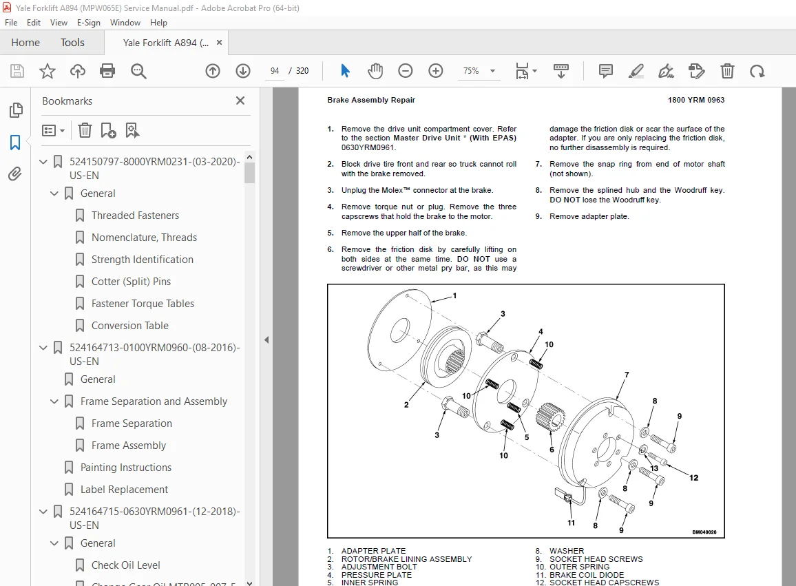
Brake Assembly Repair 90
MPW060-E and MPE060-E (Up to 10/2001)
90
Remove 90
Install 91
MPW060-E and MPE060-E (10/2001 and Up), MPE080-E, MTR005-E, MTR007-E, MPC060-E, MPC080-E, MPW065-E, MPW080-E, MSW030-040-E, MRW020-030-E, and MCW025-030-040-E
93
Remove 93
Install 95
Brake Assembly Adjustment 95
Air Gap, Adjust 95
Torque Nut, Adjust 96
Adjust 97
MPW060-E, MPW080-E, and MPE060-E Equipped With Brake Assembly Part Number 524144871 97
MPW060-E, MPW080-E, MPE060-E, and All Other Models Covered by This Section Equipped With Brake Assembly Part Number 524169212 97
Troubleshooting 98
524164718-1900YRM0964-(08-2016)-US-EN 103
General 107
Description of Operation 108
Lifting a Load 109
Lowering a Load 111
Hydraulic Lines 111
Hydraulic Oil 111
Clean 111
Sound Level 111
Special Precautions 112
Hydraulic Reservoir 114
Description 114
Drive Unit Compartment Covers 114
MPC060-E, MPC080-E, MPC060-F, and MPC080-F
114
Remove 114
Install 114
MPE060-E, MPE080-E, MPE060-F, MPE080-F, MPW060-E, MPW065-E, and MPW080-E
115
Remove 115
Install 115
Lift Pump and Motor 116
General 116
Remove 116
Lift Pump and Motor Assembly 116
Disassemble 118
Remove Reservoir 118
Remove Pump Motor 118
MPE060-E, MPE060-F, MPC060-E, MPC060-F, and MPW060-E
118
MPE080-E, MPE080-F, MPC080-E, MPC080-F, MPW065-E, and MPW080-E
118
Disassemble Pump 118
MPE060-E, MPE060-F, MPC060-E, MPC060-F, and MPW060-E
118
MPE080-E, MPE080-F, MPC080-E, MPC080-F, MPW065-E, and MPW080-E
122
Assemble 122
Assemble Pump 122
MPE060-E, MPE060-F, MPC060-E, MPC060-F, and MPW060-E
122
MPE080-E, MPE080-F, MPC080-E, MPC080-F, MPW065-E, and MPW080-E
122
Install Pump Motor 122
Install Reservoir to Pump 123
Install 123
Lift Pump and Motor Assembly 123
Valve Repair 125
Lowering Valve 125
Remove 125
Install 125
Relief Valve 125
MPE060-E, MPE060-F, MPC060-E, MPC060-F, and MPW060-E
125
Remove 125
Install 126
MPE080-E, MPE080-F, MPC080-E, MPC080-F, MPW065-E, and MPW080-E
126
Remove 126
Install 126
Check Valve 127
MPE080-E, MPE080-F, MPC080-E, MPC080-F, MPW065-E, and MPW080-E
127
Remove 127
Install 127
Lift Cylinder 128
Remove 128
Disassemble 128
Assemble 128
Install 129
Relief Valve Adjustment 130
Relief Valve Pressure Check 130
Adjust Relief Valve Pressure 131
MPE060-E, MPE060-F, MPC060-E, MPC060-F, and MPW060-E
131
MPE080-E, MPE080-F, MPC080-E, MPC080-F, MPW065-E, and MPW080-E
132
Troubleshooting 133
Lift Assemblies 133
Lift Cylinders 134
Lift Pump and Motor Assembly 135
524164719-2200YRM0928-(09-2016)-US-EN 141
General 145
Safety Precautions 145
Description 145
Curtis PMC 1297 Transistor Motor Controller 146
Principles of Operation 146
Install 146
Programming Controller 148
1307 Programmer Handset 151
Description/Features 151
Scroll Display Keys 151
Change Value Keys 151
More Info Key 151
Operation 151
Connecting Handset to Traction Motor Controller 152
Disconnecting Handset From Traction Motor Controller 152
Programmer Self-Test 152
Menu Selections 153
Program Menu 153
Test Menu 153
Diagnostics Menu 154
Diagnostic History 154
Special Program Menu 154
Programming Traction Motor Controller – 1307 Handset 154
1311 Programmer Handset 156
Description/Features 156
Menu Navigation Key 157
Data Increase/Decrease Key 158
Bookmark Keys 158
Operation 158
Connecting Handset to Traction Motor Controller 158
Disconnecting the Handset From the Traction Motor Controller 158
Main Menu Selections 159
Program Menu 159
Monitor Menu 159
Faults Menu 160
Functions menu 161
Information Menu 161
Programmer Setup Menu 161
Programming the Traction Motor Controller – 1311 Handset 161
Parameters 163
Adjusting Parameters 163
Top Speed 163
Acceleration 163
Neutral Braking 163
Plug Braking 163
Coast Braking(MPE060-E/MPE080-E Only) 163
Empty Volts 163
Battery Discharge Indicator (BDI)/Hourmeter 164
LED Fault Codes 164
Control Card Functional Test 187
524164720-2200YRM0929-(08-2016)-US-EN 191
General 195
Electrical System Checks 198
Safety Precautions 199
Repairs 200
Controller, Replace 201
Remove 201
Install 202
Contactor Coil, Check 203
Contactor, Replace 203
Contactor Tips, Replace 203
Remove 204
Install 204
Fuses 204
Brake Switch – MPW060-E, MPW065-E, MPW080-E, MPE060-E (→Aug 2003) and MPE080-E (→Aug 2003)
205
Remove and Install 205
Brake and Interlock Switches – MPE060-E (Aug 2003→) and MPE080-E (Aug 2003→) 205
Disassemble 206
Assemble 206
Height Limit 206
Control Handle 207
Disassemble 207
Control Handle Card (Old Style) 207
Control Handle Card (New Style) 208
Configure 208
Calibrate 210
Assemble 210
Remote Control Box Switches (MPE060E and MPE080E) 212
Remove 212
Install 212
Motor Maintenance – General 212
Brush and Commutator Inspection 213
Commutator Problems 215
Brush Replacement 219
Drive Motor 221
Remove 221
Disassemble 222
Assemble 223
Install 223
Lift Pump Motor 224
Remove 224
Install 224
Commutator Repairs 224
Testing the Drive Motor 225
Damaged Field and Armature 225
Short Circuit in an Armature Winding 225
Short Circuit in the Armature 226
Open Circuit in a Field Coil 226
Short Circuit in a Field Coil 226
Short Circuit Between Field and Motor Case 227
Brush Holder 227
Troubleshooting 227
524164721-4000YRM0965-(08-2016)-US-EN 231
General 235
Description of Operation 235
Load Wheel 236
Remove 236
Install 236
Caster Wheels 237
Caster Shim Adjustment 237
Caster Replacement 239
Disassemble 240
Assemble 240
Caster Lubrication 241
Rear Link and Load Wheel Assembly 242
Remove 242
Install 243
Pull Rod 247
Remove 247
End Replacement 247
Install 248
Adjust 248
Rear Fork Adjustment 249
Rocker Arm 250
Remove 250
Install 252
Upper Link 252
Remove 252
Install 253
Troubleshooting 254
524164722-8000YRM0918-(08-2016)-US-EN 259
Hydraulic System 263
Hydraulic Oils 263
Gear Oils 263
Grease 264
Truck Weights 264
Weight (Basic Truck Without Battery) 265
Tires 265
Drive Tire 265
Torque Specifications 266
Caster Assembly 266
Master Drive Unit 266
Steering 266
Brake 266
Electrical 266
Lift Mechanism 266
Battery Specifications and Adjustments 267
MPE060E and MPW060E – 24 Volt
267
MPW065E – 12 Volt
268
MPE080E – 24 Volt
268
MPW080E – 24 Volt
269
524164723-8000YRM0919-(09-2016)-US-EN 273
General 277
How to Move a Disabled Truck 278
How to Tow the Lift Truck 278
How to Raise the Lift Truck 279
Lifting Drive/Steer Tire 279
Lifting Load Wheels 280
How to Put a Lift Truck on Blocks 280
How to Raise Drive/Steer Tire 280
How to Raise Load Wheels 281
Welding Repairs 281
Maintenance Schedule 282
Checks and Inspection Procedures 282
Hydraulic System 282
Lifting Mechanism 283
Controls 283
Electrical and Battery 284
Wheels and Tires 285
Casters 285
Lubrication Instructions 286
Every 8 Hours or Daily 287
Every 50 Hours or 1 Month 287
Every 350 Hours or 2 Months 287
Check Hydraulic Oil Level 287
Every 2000 Hours or 1 Year 287
To Fill Hydraulic Reservoir 289
Recommended Schedule of Maintenance 289
Battery Maintenance 295
How to Charge the Battery 295
Equalizing Charge 295
Normal Charge 295
Maintenance-Free Battery Charger 296
How to Change the Battery 296
524164724-8000YRM0920-(02-2018)-US-EN 301
General Notes 305
S.V 06/24