Yale Forklift A967 (GLC050LX) Service Manual – PDF DOWNLOAD
$37.95
Yale Forklift A967 (GLC050LX) Service Manual – PDF DOWNLOAD
Description
Yale Forklift A967 (GLC050LX) Service Manual – PDF DOWNLOAD
FILE DETAILS:
Yale Forklift A967 (GLC050LX) Service Manual – PDF DOWNLOAD
Language : English
Pages : 2336
Downloadable : Yes
File Type : PDF
IMAGES PREVIEW OF THE MANUAL:
TABLE OF CONTENTS:
Yale Forklift A967 (GLC050LX) Service Manual – PDF DOWNLOAD
524150797-8000YRM0231-(02-2023)-US-EN 1
General 7
Threaded Fasteners 7
Nomenclature, Threads 7
Strength Identification 8
Cotter (Split) Pins 9
Fastener Torque Tables 14
Conversion Table 16
524150797-8000YRM0231-(03-2020)-US-EN 23
General 27
Threaded Fasteners 27
Nomenclature, Threads 27
Strength Identification 28
Cotter (Split) Pins 29
Fastener Torque Tables 34
Conversion Table 36
524223756-0600YRM1122-(03-2020)-US-EN 43
General 47
Serial Number 48
Engine Removal and Installation 48
Cylinder Head, Camshaft, and Valve Mechanism Repair 48
Remove 48
Clean 51
Inspect and Repair 51
Cylinder Head 51
Rocker Shaft Assembly 51
Camshaft 52
Valve Guides 53
Valve Seats 53
Valves 54
Valve Springs 54
Install 55
Crankshaft and Main Bearings Repair 59
Remove 59
Inspect and Repair 60
Crankshaft 60
Main Bearings 60
Install 61
Pistons and Connecting Rods Repair 62
Remove and Disassemble 62
Clean 62
Inspect and Repair 62
Pistons 62
Piston Rings 62
Connecting Rods and Bearings 63
Assemble and Install 63
Cylinder Block Repair 65
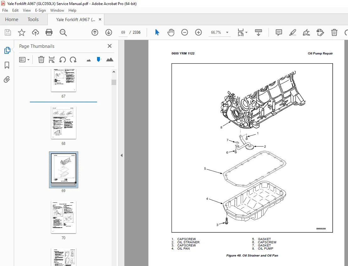
Oil Pump Repair 66
Remove 66
Disassemble 67
Clean 67
Inspect 67
Assemble 68
Install 68
Cooling System Repair 70
Thermostat 70
Replace 70
Fan Assembly 70
Remove and Disassemble 70
Assemble and Install 71
Water Pump 71
Remove 71
Install 72
Flywheel and Ring Gear Repair 73
Remove 73
Install 73
Valve Adjustment 73
Compression Pressure Check 75
Engine Timing Adjustment 76
Engine Specifications 76
Engine Data 76
Engine Speeds 76
2007, and Later, Emission Compliant Engines 76
All Engines Except 2007, and Later, Emission Compliant Engines 77
Thermostat 77
Cylinder Head 77
Valve Mechanism 77
Camshaft 78
Crankshaft 78
Connecting Rods 78
Cylinder Block 79
Pistons 79
Oil Pump 79
Torque Specifications 80
524223757-0700YRM1123-(06-2016)-US-EN 83
General 87
Cooling System Checks 87
Exhaust Leaks Into Cooling System 87
Water Flow Restrictions in Radiator 87
Radiator Hoses 87
Water Pump 88
Flushing the Cooling System 88
Cooling System, Clean 88
Radiator Replacement 89
Radiator, Remove GC/GLC030VX,
GC/GLC035VX, GC/GLC040SVX
(C809); GLP/GDP16VX, GLP/GDP18VX,
GLP/GDP20SVX (GP/GLP/GDP030VX,
GP/GLP/GDP035VX, GP/GLP/GDP040SVX)
(C810); GLC20-35VX (GC/GLC040-070VX,
GC/GLC055SVX) (A910); GLC050LX
(A967); GLP/GDP20-35VX
(GP/GLP/GDP040-070VX) (B875);
GLP/GDP20-25LX (GLP/GDP050LX)
(A974); GLC40, 45, 55VX, GLC55SVX,
(GC/GLC080, 100, 120VX, GC/GLC080,
100VXBCS, GC/GLC120SVX,
GC/GLC120VXPRS) (E818, F818) AND
GLP/GDP40VX5/VX6, GLP/GDP45SVX5,
GLP/GDP45VX6, GLP/GDP50-55VX
(GP/GLP/GDP080, 090, 100, 110, 120VX)
(F813, G813, H813, J813) 90
Radiator, Remove for Lift Trucks Models GC/GLC030VX, GC/GLC035VX,
GC/GLC040SVX (C809); GLP/GDP16VX,
GLP/GDP18VX, GLP/GDP20SVX
(GP/GLP/GDP030VX, GP/GLP/GDP035VX,
GP/GLP/GDP040SVX) (C810); GLC050LX
(A967) AND GLP/GDP20-25LX
(GLP/GDP050LX) (A974) Equipped with Oil Cooler 105
Radiator, Remove for Lift Truck Models GLC/GDC60VX,
GLC/GDC60VX, (GC/GLC/GDC135VX,
GC/GLC/GDC135VX) (C879, D879, E879,
F879) 108
Radiator , Remove for Lift Truck Models GLP/GDP60VX, GLP/GDP70VX
(GP/GLP/GDP135VX, GP/GLP/GDP155VX)
(C878, D878, E878) and GLP/GDP80VX,
GLP/GDP80VX9, GLP/GDP90VX
(GLP/GDP170VX, GLP/GDP175VX36,
GLP/GDP190VX) (A909, B909) 111
Radiator, Install for Lift Truck Models GC/GLC030VX,
GC/GLC035VX, GC/GLC040SVX
(C809); GLP/GDP16VX, GLP/GDP18VX,
GLP/GDP20SVX (GP/GLP/GDP030VX,
GP/GLP/GDP035VX, GP/GLP/GDP040SVX)
(C810); GLC20-35VX (GC/GLC040-070VX,
GC/GLC055SVX) (A910); GLC050LX
(A967); GLP/GDP20-35VX
(GP/GLP/GDP040-070VX) (B875);
GLP/GDP20-25LX (GLP/GDP050LX)
(A974); GLC40, 45, 55VX; GLC55SVX;
(GC/GLC080, 100, 120VX; GC/GLC080,
100VXBCS; GC/GLC120SVX;
GC/GLC120VXPRS) (E818, F818) and
GLP/GDP40VX5/VX6; GLP/GDP45SVX5,
GLP/GDP45VX6, GLP/GDP50-55VX
(GP/GLP/GDP080, 090, 100, 110, 120VX)
(F813, G813, H813, J813) 118
Radiator, Install for Lift Truck Models GC/GLC030VX, GC/GLC035VX,
GC/GLC040SVX (C809); GLP/GDP16VX,
GLP/GDP18VX, GLP/GDP20SVX
(GP/GLP/GDP030VX, GP/GLP/GDP035VX,
GP/GLP/GDP040SVX) (C810); GLC050LX
(A967) and GLP/GDP20-25LX
(GLP/GDP050LX) (A974) Equipped with Oil Cooler 123
Radiator, Install for Lift Truck Models GLC/GDC60VX,
GLC/GDC60VX, (GC/GLC/GDC135VX,
GC/GLC/GDC135VX) (C879, D879, E879,
F879) 125
Radiator, Install for Lift Truck Models GLP/GDP60VX, GLP/GDP70VX (GP/GLP/GDP135VX, GP/GLP/GDP155VX) (C878, D878, E878) and GLP/GDP80VX, GLP/GDP80VX9, GLP/GDP90VX (GLP/GDP170VX, GLP/GDP175VX36, GLP/GDP190VX) (A909, B909) 128
Fan Assembly Replacement 140
Fan Removal 140
Inspect 155
Fan Installation 155
524223757-0700YRM1123-(06-2021)-US-EN 161
General 165
Cooling System Checks 165
Exhaust Leaks Into Cooling System 165
Water Flow Restrictions in Radiator 165
Radiator Hoses 165
Water Pump 165
Flushing the Cooling System 167
Cooling System, Clean 167
Radiator Replacement 169
Radiator, Remove GC/GLC030VX,GC/GLC035VX, GC/GLC040SVX(C809); GLP/GDP16VX, GLP/GDP18VX,GLP/GDP20SVX (GP/GLP/GDP030VX,GP/GLP/GDP035VX, GP/GLP/GDP040SVX)(C810); GLC20-35VX (GC/GLC040-070VX,GC/GLC055SVX) (A910); GLC050LX(A967); GLP/GDP20-35VX(GP/GLP/GDP040-070VX) (B875);GLP/GDP20-25LX (GLP/GDP050LX)(A974); GLC40, 45, 55VX, GLC55SVX,(GC/GLC080, 100, 120VX, GC/GLC080,100VXBCS, GC/GLC120SVX,GC/GLC120VXPRS) (E818, F818) ANDGLP/GDP40VX5/VX6, GLP/GDP45SVX5,GLP/GDP45VX6, GLP/GDP50-55VX(GP/GLP/GDP080, 090, 100, 110, 120VX)(F813, G813, H813, J813) 169
Radiator, Remove for Lift Trucks Models Equipped with Oil CoolerGC/GLC030VX, GC/GLC035VX,GC/GLC040SVX (C809); GLP/GDP16VX,GLP/GDP18VX, GLP/GDP20SVX(GP/GLP/GDP030VX, GP/GLP/GDP035VX,GP/GLP/GDP040SVX) (C810); GLC050LX(A967) AND GLP/GDP20-25LX(GLP/GDP050LX) (A974) 184
Radiator, Remove for Lift Truck Models GLC/GDC60VX,GLC/GDC60VX, (GC/GLC/GDC135VX,GC/GLC/GDC135VX) (C879, D879, E879,F879, G879) 187
Radiator , Remove for Lift Truck Models GLP/GDP60VX, GLP/GDP70VX(GP/GLP/GDP135VX, GP/GLP/GDP155VX)(C878, D878, E878) and GLP/GDP80VX,GLP/GDP80VX9, GLP/GDP90VX(GLP/GDP170VX, GLP/GDP175VX36,GLP/GDP190VX) (A909, B909) 190
Radiator, Install for Lift Truck Models GC/GLC030VX,GC/GLC035VX, GC/GLC040SVX(C809); GLP/GDP16VX, GLP/GDP18VX,GLP/GDP20SVX (GP/GLP/GDP030VX,GP/GLP/GDP035VX, GP/GLP/GDP040SVX)(C810); GLC20-35VX (GC/GLC040-070VX,GC/GLC055SVX) (A910); GLC050LX(A967); GLP/GDP20-35VX(GP/GLP/GDP040-070VX) (B875);GLP/GDP20-25LX (GLP/GDP050LX)(A974); GLC40, 45, 55VX; GLC55SVX;(GC/GLC080, 100, 120VX; GC/GLC080,100VXBCS; GC/GLC120SVX;GC/GLC120VXPRS) (E818, F818) andGLP/GDP40VX5/VX6; GLP/GDP45SVX5,GLP/GDP45VX6, GLP/GDP50-55VX(GP/GLP/GDP080, 090, 100, 110, 120VX)(F813, G813, H813, J813) 196
Radiator, Install for Lift Truck Models Equipped with Oil CoolerGC/GLC030VX, GC/GLC035VX,GC/GLC040SVX (C809); GLP/GDP16VX,GLP/GDP18VX, GLP/GDP20SVX(GP/GLP/GDP030VX, GP/GLP/GDP035VX,GP/GLP/GDP040SVX) (C810); GLC050LX(A967) and GLP/GDP20-25LX(GLP/GDP050LX) (A974) 200
Radiator, Install for Lift Truck Models GLC/GDC60VX,GLC/GDC60VX, (GC/GLC/GDC135VX,GC/GLC/GDC135VX) (C879, D879, E879,F879, G879) 201
Radiator, Install for Lift Truck Models GLP/GDP60VX, GLP/GDP70VX (GP/GLP/GDP135VX, GP/GLP/GDP155VX) (C878, D878, E878) and GLP/GDP80VX, GLP/GDP80VX9, GLP/GDP90VX (GLP/GDP170VX, GLP/GDP175VX36, GLP/GDP190VX) (A909, B909) 204
Fan Assembly Replacement 215
Fan Removal 215
Inspect 229
Fan Installation 230
524223765-1800YRM1135-(09-2018)-US-EN 235
General 239
Dry Brake System 239
Wet Brake System 239
Service Brakes Repair (Dry Brake) 239
Remove and Disassemble 240
Clean 248
Inspect 248
Assemble and Install 249
Adjust 256
Inching Overlap Adjustment 256
Parking Brake Repair 257
Remove and Disassemble 257
Assemble and Install 260
Adjust 260
Master Cylinder Repair 261
Remove (Dry Brake) 261
Disassemble (Dry Brake) 262
Clean and Inspect (Dry Brake) 264
Assemble (Dry Brake) 264
Bench Bleed Master Cylinder (Dry Brake) 264
Install and Adjust (Dry Brake) 264
Remove (Wet Brake) 265
Disassemble (Wet Brake) 267
Clean and Inspect (Wet Brake) 268
Assemble (Wet Brake) 269
Install and Adjust (Wet Brake) 269
Service Brakes Adjustment (Dry Brake) 270
Brake System Air Removal 270
Using Pressure Bleed System 270
Using Brake Pedal Pressure 271
Brake Pedal Adjustment 271
Free Pedal Adjustment 272
Torque Specifications 274
524223766-1900YRM1136-(01-2022)-US-EN 277
General 281
Hydraulic Gear Pump Assembly 282
Variable Displacement Pump Assembly 283
Single Gear Pump Assembly Repair 284
Remove 284
Disassemble 290
Clean 292
Inspect 292
Assemble 292
Install 292
Tandem Gear Pump Assembly 297
Remove 297
Disassemble 298
Clean 301
Inspect 301
Assemble 301
Install 302
Gear Pump Specifications 303
24 0 to 45 0 cc/rev – Variable Displacement Pump Repair 309
Remove 309
Disassemble 319
Clean 322
Inspect 323
Assemble 323
Install 323
63 0 cc/rev – Variable Displacement Pump Repair 328
Remove 328
Disassemble 331
Clean 333
Inspect 333
Assemble 333
Install 333
Variable Displacement Pump Checks and Adjustments (Single Pump) 337
Margin Pressure Check 337
Flow Compensator Adjustment 338
Pressure Compensator Adjustment 338
Variable Displacement Pump Checks and Adjustments (Tandem Pump) 340
Variable Displacement Pump Specifications 343
Torque Specifications 345
Hydraulic Gear Pump 345
Variable Displacement Pump 346
Special Tools 347
524223766-1900YRM1136-(11-2017)-US-EN 349
General 353
Hydraulic Gear Pump Assembly 354
Variable Displacement Pump Assembly 355
Single Gear Pump Assembly Repair 355
Remove 355
Disassemble 362
Clean 362
Inspect 364
Assemble 364
Install 364
Tandem Gear Pump Assembly 368
Remove 369
Disassemble 371
Clean 373
Inspect 373
Assemble 373
Install 374
Gear Pump Specifications 374
24 0 to 45 0 cc/rev – Variable Displacement Pump Repair 380
Remove 380
Disassemble 390
Clean 393
Inspect 393
Assemble 393
Install 394
63 0 cc/rev – Variable Displacement Pump Repair 397
Remove 397
Disassemble 400
Clean 400
Inspect 400
Assemble 402
Install 402
Variable Displacement Pump Checks and Adjustments (Single Pump) 404
Margin Pressure Check 404
Flow Compensator Adjustment 405
Pressure Compensator Adjustment 405
Variable Displacement Pump Checks and Adjustments (Tandem Pump) 406
Variable Displacement Pump Specifications 409
Torque Specifications 410
Hydraulic Gear Pump 411
Variable Displacement Pump 412
Special Tools 412
524223767-2000YRM1137-(01-2017)-US-EN 417
General 423
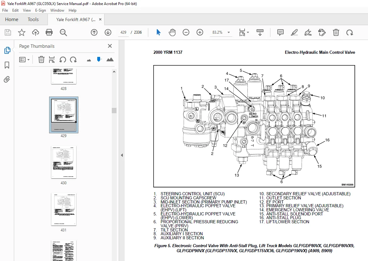
Electro-Hydraulic Main Control Valve 424
Description 424
Remove 432
Electro-Hydraulic Control Valve Sections 437
General 437
Outlet Control Valve Section 437
Remove 437
Disassemble 438
Clean 440
Inspect 440
Assemble 440
Install 441
Auxiliary Control Valve Sections 441
Remove 441
Disassemble 448
Clean 449
Inspect 450
Assemble 450
Install 452
Tilt Control Valve Section 453
Remove 453
Disassemble 453
Clean 459
Inspect 459
Assemble 459
Install 460
Lift/Lower Control Valve Section 461
Remove 461
Disassemble 461
Clean 470
Inspect 470
Assemble 470
Install 471
Mid-Inlet Section 471
Remove 471
Clean 472
Inspect 472
Install 472
Install 472
Electro Hydraulic Poppet Valve (EHPV) Pilot Pin Adjustment 477
Lift Pilot Pin 477
Lower Pilot Pin 481
Abnormal/Erroneous EHPV Adjustment 483
Manual Main Control Valve 484
Description 484
Remove 488
OPS Solenoid Assembly 496
General 496
Remove 497
Clean and Inspect 500
Install 500
Manual Control Valve Sections 501
General 501
Outlet Control Valve Section 501
Remove 501
Disassemble 501
Clean 504
Inspect 504
Assemble 504
Install 505
Auxiliary Control Valve Sections 505
Remove 505
Disassemble 505
Clean 508
Inspect 508
Assemble 508
Install 509
Lift/Tilt Control Valve Section 509
Remove 509
Disassemble 509
Clean 516
Inspect 516
Assemble 517
Install 518
Mid-Inlet Section 519
Remove 519
Clean 519
Inspect 519
Install 519
Install 520
Pressure Relief Valve Check and Adjustment 526
Primary Relief Valve 527
Secondary Relief Valve 531
Steering Control Unit Repair 538
Steering Control Unit, Remove 538
Steering Control Unit, Disassemble 542
Steering Control Unit, Clean 544
Steering Control Unit, Inspect 544
Steering Control Unit, Assemble 544
Relief Valve, Disassemble 545
Relief Valve, Clean 545
Relief Valve, Inspect 546
Relief Valve, Assemble 546
Steering Control Unit, Install 546
524223767-2000YRM1137-(06-2021)-US-EN 551
General 555
Electro-Hydraulic Main Control Valve 556
Description 556
Remove 564
Electro-Hydraulic Control Valve Sections 569
General 569
Outlet Control Valve Section 569
Remove 569
Disassemble 569
Clean 572
Inspect 572
Assemble 573
Install 573
Auxiliary Control Valve Sections 573
Remove 574
Disassemble 579
Clean 581
Inspect 581
Assemble 581
Install 583
Tilt Control Valve Section 584
Remove 584
Disassemble 585
Clean 589
Inspect 589
Assemble 590
Install 591
Lift/Lower Control Valve Section 591
Remove 591
Disassemble 591
Clean 597
Inspect 597
Assemble 597
Install 598
Mid-Inlet Section 598
Remove 598
Clean 599
Inspect 599
Install 599
Install 599
Electro Hydraulic Poppet Valve (EHPV) Pilot Pin Adjustment 604
Lift Pilot Pin 604
Lower Pilot Pin 607
Abnormal/Erroneous EHPV Adjustment 609
Manual Main Control Valve 610
Description 610
Remove 614
OPS Solenoid Assembly 622
General 622
Remove 623
Clean and Inspect 625
Install 625
Manual Control Valve Sections 626
General 626
Outlet Control Valve Section 626
Remove 626
Disassemble 626
Clean 629
Inspect 629
Assemble 629
Install 629
Auxiliary Control Valve Sections 630
Remove 630
Disassemble 630
Clean 633
Inspect 633
Assemble 633
Install 633
Lift/Tilt Control Valve Section 634
Remove 634
Disassemble 634
Clean 640
Inspect 640
Assemble 640
Install 642
Mid-Inlet Section 642
Remove 642
Clean 643
Inspect 643
Install 643
Install 643
Pressure Relief Valve Check and Adjustment 651
Primary Relief Valve 651
Secondary Relief Valve 654
Steering Control Unit Repair 659
Steering Control Unit, Remove 659
Steering Control Unit, Disassemble 663
Steering Control Unit, Clean 665
Steering Control Unit, Inspect 665
Steering Control Unit, Assemble 665
Relief Valve, Disassemble 666
Relief Valve, Clean 666
Relief Valve, Inspect 667
Relief Valve, Assemble 667
Steering Control Unit, Install 667
524223768-2100YRM1139-(02-2014)-US-EN 671
524223769-2200YRM1128-(01-2023)-US-EN 719
Series Code / Model Designation Reference Table 727
General 729
Deutsch Crimping Tool 730
How to Strip a Wire for Use With Deutsch Crimping Tool 730
How to Crimp With the Deutsch Crimping Tool 731
Calibration Test for the Deutsch Crimping Tool 733
Deutsch Connectors 735
DT, DTM, and DTP Series Connectors 735
HD Series Connectors 778
Metri-Pack Connectors 800
Remove and Install 800
Micro-Pack Connectors 803
Weather-Pack Connectors 804
AMPSEAL Crimping Tools 806
AMP Hand Crimping Tool With Certi-Crimp 806
Description 806
Stripping Wire for Use with AMP Hand Crimping Tool 807
Insulation Crimp Adjustment 808
Maintenance and Inspection for AMP Hand Crimping Tool 808
AMP Hand Crimping Tool 808
Crimp Height Inspection 808
How to use AMP Hand Crimping Tool 809
AMP Pro-Crimper II Tool 809
Description 809
Remove and Install Die Set and Locator Assembly 810
Stripping Wire for Use With AMP PRO-CRIMPER II Tool 810
Contact Support Adjustment 811
Crimp Height Adjustment 812
Maintenance and Inspection Procedures 812
PRO-CRIMPER II Tool 812
Crimp Height Inspection 812
How to Use AMP PRO-CRIMPER II Tool 813
AMPSEAL Connector Assemblies 814
Description for Plug Connector Assembly 814
Seal Plug 815
Contact Crimping 815
Description for Plug Connector and Header Assembly 820
Voltage Reading 823
Seal Plug 823
Contact Crimping 823
AMP Superseal 1 5 Crimping Tools 830
Mini Mic Receptacle and Tab Contacts 830
Description 830
Crimping Conditions and Measurements 830
Insertion of Rubber Seal on Cable 832
AMP Hand Application Tool 837
Description 837
Maintenance and Inspection 837
Crimp Height Inspection 837
Crimp Height Adjustment 838
How to Use AMP Hand Application Tool 838
AMP Pro-Crimper II Tool 839
Description 839
Remove and Install Die Set and Locator Assembly 839
Adjustments 840
Contact Support 840
Crimp Height 841
Inspections and Maintenance 842
Crimp Height Inspection 842
Visual Inspection 842
Maintenance 843
How to Use Pro-Crimper II Tool 843
AMP Superseal 1 5 Connector Assemblies 844
Description 844
Repair and Maintenance 851
Panel Mount Option 851
AMP Fastin-Faston Hand Tools 852
Description – AMP Double Action Hand Tool 852
Maintenance and Inspection Procedures 852
Daily Maintenance 852
Periodic Tool Inspection 853
Lubrication 853
Visual Inspection 853
Crimp Height Inspection 853
Certi-Crimp Ratchet Inspection 854
How to Use AMP Double Action Hand Tool 855
Description – AMP Extraction Tool 856
Maintenance and Inspection 857
How to Use AMP Extraction Tool 857
AMP Fastin-Faston Receptacles and Housings 859
Description 859
Wire Repair 867
Wire Splicing Requirements 867
Deutsch Jiffy Splice 868
Twisted/Shielded Cable and Leads Repair 874
Special Tools 876
524223769-2200YRM1128-(07-2020)-US-EN 885
Series Code / Model Designation Reference Table 891
General 894
Deutsch Crimping Tool 894
How to Strip a Wire for Use With Deutsch Crimping Tool 894
How to Crimp With the Deutsch Crimping Tool 895
Calibration Test for the Deutsch Crimping Tool 897
Deutsch Connectors 899
DT, DTM, and DTP Series Connectors 899
HD Series Connectors 941
Metri-Pack Connectors 964
Remove and Install 964
Micro-Pack Connectors 966
Weather-Pack Connectors 967
AMPSEAL Crimping Tools 969
AMP Hand Crimping Tool With Certi-Crimp 969
Description 969
Stripping Wire for Use with AMP Hand Crimping Tool 969
Insulation Crimp Adjustment 970
Maintenance and Inspection for AMP Hand Crimping Tool 970
AMP Hand Crimping Tool 970
Crimp Height Inspection 970
How to use AMP Hand Crimping Tool 971
AMP Pro-Crimper II Tool 971
Description 971
Remove and Install Die Set and Locator Assembly 972
Stripping Wire for Use With AMP PRO-CRIMPER II Tool 973
Contact Support Adjustment 973
Crimp Height Adjustment 974
Maintenance and Inspection Procedures 974
PRO-CRIMPER II Tool 974
Crimp Height Inspection 974
How to Use AMP PRO-CRIMPER II Tool 975
AMPSEAL Connector Assemblies 976
Description for Plug Connector Assembly 976
Seal Plug 977
Contact Crimping 977
Description for Plug Connector and Header Assembly 982
Voltage Reading 984
Seal Plug 984
Contact Crimping 984
AMP Superseal 1 5 Crimping Tools 991
Mini Mic Receptacle and Tab Contacts 991
Description 991
Crimping Conditions and Measurements 991
Insertion of Rubber Seal on Cable 993
AMP Hand Application Tool 998
Description 998
Maintenance and Inspection 998
Crimp Height Inspection 998
Crimp Height Adjustment 999
How to Use AMP Hand Application Tool 999
AMP Pro-Crimper II Tool 1000
Description 1000
Remove and Install Die Set and Locator Assembly 1001
Adjustments 1001
Contact Support 1001
Crimp Height 1002
Inspections and Maintenance 1003
Crimp Height Inspection 1003
Visual Inspection 1003
Maintenance 1004
How to Use Pro-Crimper II Tool 1004
AMP Superseal 1 5 Connector Assemblies 1005
Description 1005
Repair and Maintenance 1012
Panel Mount Option 1012
AMP Fastin-Faston Hand Tools 1013
Description – AMP Double Action Hand Tool 1013
Maintenance and Inspection Procedures 1013
Daily Maintenance 1013
Periodic Tool Inspection 1014
Lubrication 1014
Visual Inspection 1014
Crimp Height Inspection 1014
Certi-Crimp Ratchet Inspection 1015
How to Use AMP Double Action Hand Tool 1016
Description – AMP Extraction Tool 1017
Maintenance and Inspection 1017
How to Use AMP Extraction Tool 1018
AMP Fastin-Faston Receptacles and Housings 1019
Description 1019
Wire Repair 1026
Wire Splicing Requirements 1026
Deutsch Jiffy Splice 1027
Twisted/Shielded Cable and Leads Repair 1032
Special Tools 1035
524289374-0900YRM1326-(04-2018)-US-EN 1043
General 1049
LPG Tank and Bracket Replacement 1049
Remove LPG Tank for Lift Truck Models GLC030VX, GLC035VX, GLC040SVX (C809), GLP/GDP16VX, GLP/GDP18VX, GLP/GDP20SVX (GP/GLP/GDP030VX, GP/GLP/GDP035VX, GP/GLP/GDP040SVX) (C810), GLC20-35VX (GLC040-070VX, GLC055SVX) (A910), and GLP/GDP20-35VX (GP/GLP/GDP040-070VX) (B875) 1049
Install LPG Tank for Lift Truck Models GLC030VX, GLC035VX, GLC040SVX (C809), GLP/GDP16VX, GLP/GDP18VX, GLP/GDP20SVX (GP/GLP/GDP030VX, GP/GLP/GDP035VX, GP/GLP/GDP040SVX) (C810), GLC20-35VX (GLC040-070VX, GLC055SVX) (A910), and GLP/GDP20-35VX (GP/GLP/GDP040-070VX) (B875) 1051
Remove LPG Tank for Lift Truck Models GLC050LX (A967) and GLP20-25LX (GLP050LX) (A974) 1052
LPG Tank Install for Lift Truck Models GLC050LX (A967) and GLP20-25LX (GLP050LX) (A974) 1054
Remove LPG Bracket for Lift Truck Models GLC030VX, GLC035VX, GLC040SVX (C809), GLP/GDP16VX, GLP/GDP18VX, GLP/GDP20SVX (GP/GLP/GDP030VX, GP/GLP/GDP035VX, GP/GLP/GDP040SVX) (C810), GLC20-35VX (GLC040-070VX, GLC055SVX) (A910), and GLP/GDP20-35VX (GP/GLP/GDP040-070VX) (B875) 1055
Install LPG Bracket for Lift Truck Models GLC030VX, GLC035VX, GLC040SVX (C809), GLP/GDP16VX, GLP/GDP18VX, GLP/GDP20SVX (GP/GLP/GDP030VX, GP/GLP/GDP035VX, GP/GLP/GDP040SVX) (C810), GLC20-35VX (GLC040-070VX, GLC055SVX) (A910), and GLP/GDP20-35VX (GP/GLP/GDP040-070VX) (B875) 1057
Remove LPG Tank Bracket Alignment Pin, Lift Truck Models GLC030VX, GLC035VX, GLC040SVX (C809), GLP/GDP16VX, GLP/GDP18VX, GLP/GDP20SVX (GP/GLP/GDP030VX, GP/GLP/GDP035VX, GP/GLP/GDP040SVX) (C810), GLC20-35VX (GLC040-070VX, GLC055SVX) (A910), and GLP/GDP20-35VX (GP/GLP/GDP040-070VX) (B875) 1058
Install LPG Tank Bracket Alignment Pin, Lift Truck Models GLC030VX, GLC035VX, GLC040SVX (C809), GLP/GDP16VX, GLP/GDP18VX, GLP/GDP20SVX (GP/GLP/GDP030VX, GP/GLP/GDP035VX, GP/GLP/GDP040SVX) (C810), GLC20-35VX (GLC040-070VX, GLC055SVX) (A910), and GLP/GDP20-35VX (GP/GLP/GDP040-070VX) (B875) 1060
Remove LPG Bracket for Lift Truck Models and GLC050LX (A967) and GLP20-25LX (GLP050LX) (A974) 1061
Install LPG Bracket for Lift Truck Models GLC050LX (A967) and GLP20-25LX (GLP050LX) (A974) 1061
Fuel Filter Unit Repair 1061
Fuel Filter Element 1061
Remove 1061
Clean/Inspect 1062
Install 1062
Fuel Filter Housing 1062
Remove 1062
Disassemble 1065
Assemble 1067
Install 1068
Electronic Throttle Body Repair 1068
Remove 1068
Install 1070
Electronic Pressure Regulator (EPR) Repair 1070
Remove 1071
Disassemble 1075
Assemble 1077
Install 1078
LPG Shutoff Valve Assembly 1078
Remove 1078
Install 1082
Fuel Mixer Repair 1084
Remove 1084
Install 1087
Control System 1087
Engine Control Unit (ECU) 1087
Remove 1087
Install 1089
Low LPG Pressure Switch 1089
Remove 1089
Install 1090
LPG Low Level Sensor 1090
Remove 1091
Install 1094
Exhaust System 1095
Counterweight Exhaust System 1095
Remove and Disassemble 1095
Inspect 1097
Assemble and Install 1097
Overhead Exhaust System 1097
Remove and Disassemble 1098
Inspect 1100
Assemble and Install 1100
Exhaust Manifold 1101
Remove 1101
Install 1102
Positive Crankcase Ventilation (PCV) Valve 1103
Remove 1103
Inspect 1103
Install 1103
Oxygen Sensor 1103
Remove 1103
Install 1105
LPG Fuel Testing 1106
General 1106
Available Fuel Tests 1106
Composition Test (ASTM D-2163) 1106
Ammonia Test (ASTM D-4490) 1106
Basic Nitrogen Test (ASTM UOP269-90) 1106
Residues Test (ASTM D-2158) 1106
Vapor Pressure Test (ASTM D-2598) 1106
Sulfur Compounds Test (ASTM D-5623) 1107
Methanol Test (ASTM D-4864) 1107
Copper Corrosion (ASTM D-1838) 1107
Where To Send LPG Fuel Samples For Testing 1107
524289375-2200YRM1327-(09-2012)-US-EN 1111
General 1115
Ignition System 1115
General 1115
Ignition Timing Adjustment, Gasoline and LPG 1115
Spark Plugs Check 1120
Spark Plug Wires Check 1120
Coil Replacement 1121
Remove 1121
Inspect 1122
Install 1122
Starter Repair 1123
General 1123
Remove 1123
No-Load Test 1124
Magnetic Switch Test 1125
Pull-Out Test 1125
Holding Coil Test 1125
Return Test 1125
Pinion Movement Inspection 1126
Install 1126
Alternator Repair 1126
General 1126
Charging System Inspection 1128
Output Current Check 1128
No-Load Adjusted Voltage Check 1129
Remove 1130
Inspect 1130
Rectifier Check 1130
Install 1131
Engine Sensors and Switches 1132
Oil Pressure Sensor, Gas and LPG Engines 1132
Remove 1132
Install 1132
Air Filter Restriction Switch, Gas and LPG Engines 1132
Remove 1132
Install 1132
Cam Angle Sensor, Gas and LPG Engines 1133
Remove 1133
Install 1134
Voltage Check 1134
Manifold Absolute Pressure (MAP) Sensor, Gas and LPG Engines 1135
Remove 1135
Install 1136
Intake Air Temperature (IAT) Sensor, LPG Engines 1137
Remove 1137
Install 1137
Intake Air Temperature (IAT) Sensor, Gas Engines 1137
Remove 1137
Install 1137
Fuel Temperature Sensor, LPG Engines 1140
Remove 1140
Install 1140
Engine Coolant Temperature (ECT) Sensor 1141
2007 Emissions Compliant Gas Engines 1141
Remove 1141
Install 1141
2007 and 2010 Emissions Compliant LPG Engines 1142
Remove 1142
Install 1142
2010 Emissions Compliant Gas and LPG Engines 1144
Remove 1144
Install 1144
550010194-1300YRM1421-(08-2013)-US-EN 1149
toc 1149
Single Speed PowerShift 1149
Safety Precautions Maintenance and Repair 1150
General 1153
Serial Number 1153
Hydraulic Gear Pump 1154
Remove 1154
Install 1154
Charge Pump Repair 1155
Original Charge Pump 1155
Remove 1155
Disassemble 1156
Clean 1156
Inspect 1156
Assemble 1156
Install 1156
New Charge Pump, Manufactured After July, 2013 1157
Remove 1157
Clean 1158
Inspect 1158
Install 1159
Torque Converter Replacement 1161
Remove 1161
Clean and Inspect 1161
Install 1161
Stator Support Assembly Repair 1162
Remove 1162
Disassemble 1167
Clean 1168
Inspect 1168
Assemble 1169
Install 1169
Clutch Packs Repair 1171
Remove 1171
Engine, Torque Converter, and Transmission Assembly 1171
Transmission Components 1172
Disassemble 1174
Transmission 1174
Housings 1174
Forward Clutch Pack 1177
Reverse Clutch Pack 1182
Clean 1188
Inspect 1188
Assemble 1189
Transmission 1189
Reverse Clutch Pack 1189
Forward Clutch Pack 1196
Housings 1202
Install 1204
Transmission Components 1204
Engine, Torque Converter, and Transmission Assembly 1207
Inching Overlap Adjustment 1207
Proportional and Enable Solenoid Valves 1208
Proportional Valves 1208
Remove 1208
Disassemble 1210
Clean and Inspect 1210
Assemble 1210
Install 1210
Enable Solenoid Valve 1210
Remove 1210
Disassemble 1210
Clean and Inspect 1210
Assemble 1211
Install 1211
Foot Directional Control Pedal Repair 1211
Remove and Disassembly 1211
Clean and Inspect 1215
Assemble and Install 1215
550013974-0100YRM1423-(03-2012)-US-EN 1219
toc 1219
Frame 1219
Safety Precautions Maintenance and Repair 1220
General 1223
Hood, Seat, and Side Covers Replacement 1224
Remove 1224
Install 1230
Belly Pan (Optional) 1231
Remove 1231
Clean and Inspect 1231
Install 1231
Steering Column 1232
Description 1232
Steering Column Repair 1232
Remove 1232
Disassemble 1233
Clean 1236
Inspect 1236
Assemble 1236
Install 1236
Counterweight Replacement 1237
Remove 1237
Install 1239
Overhead Guard Replacement 1239
Remove 1239
Install 1240
Rain Top (Optional) 1240
Remove 1240
Clean and Inspect 1240
Install 1240
Operator Restraint System Replacement 1241
Description 1241
Emergency Locking Retractor (ELR) 1241
Engine Replacement 1243
Remove 1243
LPG Engine 1243
Diesel Engine 1251
Install 1256
LPG Engine 1256
Diesel Engine 1257
Transmission Replacement 1258
Remove 1258
Install 1260
Throttle Pedal and Cable Adjustment 1261
Mazda LPG Engine 1261
Throttle Pedal Stop Adjustment 1261
Yanmar Diesel Engine 1261
Yanmar Diesel Engine With Electronic Throttle 1263
Cooling System 1263
Description 1263
Hydraulic Filter Repair 1263
Remove 1263
Clean and Inspect 1264
Install 1264
Tank Repair 1264
LPG Tank Repair 1264
Hydraulic and Diesel Tanks 1264
Inspect 1264
Clean 1265
Steam Method of Cleaning 1265
Chemical Solution Method of Cleaning 1266
Additional Preparations for Repair 1266
Small Leaks, Repair 1266
Large Leaks, Repair 1266
Preparations for Use After Repair 1267
Label Replacement 1267
tables 1219
Table 1 Weight of Counterweights 1238
550013975-1400YRM1426-(07-2011)-US-EN 1275
toc 1275
Drive Axle and Differential Assembly Repair 1275
Safety Precautions Maintenance and Repair 1276
General 1279
Identification Plate 1279
Drive Axle Repair 1280
Remove and Disassemble 1280
Clean and Inspect 1283
Assemble and Install 1283
Differential Repair 1286
Remove 1286
Differential Assembly From Drive Axle Center Section Assembly 1286
Drive Pinion, Pinion Gear, and Bearings From Drive Axle Center S 1288
Disassemble 1293
Differential Assembly 1293
Drop Box Housing 1297
Differential Assembly Cover 1298
Drive Axle Center Section 1299
Clean and Inspect 1300
Assemble 1301
Drive Axle Center Section 1301
Differential Assembly Cover 1303
Drop Box Housing 1304
Differential Assembly 1305
Install 1309
Pinion Inner Shim Set, Adjust Thickness (Depth of Pinion) 1309
Drive Pinion, Pinion Gear, and Bearings Into Drive Axle Center S 1311
Differential Assembly Into Drive Axle Center Section 1315
Hypoid Gear Backlash, Adjust 1318
Hypoid Gear, Runout Check 1319
Gear Set, Tooth Contact Pattern Check 1319
Torque Specifications 1322
tables 1275
Table 1 Pinion Variation Numbers Examples 1310
Table 2 Ring and Pinion Tooth Contact Adjustment 1320
Table 3 Correct Tooth Contact 1320
Table 4 Incorrect Tooth Contact 1321
550013976-1600YRM1425-(07-2011)-US-EN 1325
toc 1325
Steering Axle 1325
Safety Precautions Maintenance and Repair 1326
General 1329
Steering Axle Assembly Repair 1330
Remove 1330
Disassemble 1330
Clean 1332
Inspect 1332
Assemble 1333
Install 1334
Spindles, Bearings, and Tie Rods Repair 1336
Spindles and Bearings 1336
Remove 1336
Disassemble 1336
Clean 1337
Inspect 1337
Assemble 1337
Install 1338
Tie Rods 1338
Remove 1338
Disassemble 1339
Clean 1339
Inspect 1339
Assemble 1339
Install 1340
Steering Cylinder Repair 1340
Remove 1340
Disassemble 1340
Clean 1341
Inspect 1342
Assemble 1342
Install 1342
Torque Specifications 1342
550013977-2200YRM1427-(03-2012)-US-EN 1345
toc 1345
Electrical System 1345
Safety Precautions Maintenance and Repair 1346
General 1349
Engine Control Module (ECM), Yanmar Diesel Engine 1350
Remove 1350
Install 1350
Display Switch Cluster 1351
Remove 1351
Install 1352
Direction Control Lever 1353
Remove 1353
Install 1353
Key Switch 1354
Remove 1354
Install 1354
Display Switch Cluster Panel Bezel and Overlay 1355
Remove 1355
Install 1355
Steering Column Repair 1355
Remove 1355
Disassemble 1355
Assemble 1356
Install 1356
Sensors and Switches 1357
General 1357
Dash Panel, Kick Panel, and Seal Plate, Remove and Install 1357
Remove 1357
Install 1357
Accelerator Pedal Position Sensor 1358
Remove 1358
Install 1359
Brake Fluid Level Switch 1360
Remove 1360
Install 1361
Brake Pedal Position Sensor 1361
Remove 1361
Install 1361
Parking Brake Position Sensor 1362
Remove 1362
Install 1363
Seat Sensor (Operator Presence System) 1363
Non-Suspension Seat 1363
Remove 1363
Install 1364
Full Suspension Seats 1364
Remove 1364
Install 1364
Transmission Pressure Sensors (Transducers) 1365
Remove 1365
Install 1365
Transmission Temperature Sensor 1365
Remove 1365
Install 1366
Rear Horn Button Switch 1366
Remove 1366
Install 1366
Engine and Fuel Sensors and Switches, Mazda 2 0L LPG Trucks 1367
Engine and Fuel Sensors, Yanmar 2 6L Diesel Trucks 1367
Engine Speed Sensor 1367
Remove 1367
Install 1367
Oil Pressure Sensor 1367
Remove 1367
Install 1368
Engine Coolant Temperature (ECT) Sensor 1368
Remove 1368
Install 1368
Fuel/Water Separator Sensor 1369
Remove 1369
Install 1369
Glow Plug Relay 1370
Remove 1370
Install 1370
Power Distribution Module (PDM) and Component Parts 1372
Power Distribution Module (PDM) as a Unit 1372
Remove 1372
Install 1372
Power Distribution Module (PDM) Components 1374
Remove and Install 1374
Battery 1374
Remove 1374
Install 1374
Lights 1375
Work Lights (Front and Rear) 1375
Remove 1375
Install 1375
Strobe Light 1375
Remove 1375
Install 1375
LED Tail, Backup, and Brake Lights 1376
Remove 1376
Install 1376
Reflectors 1376
Remove 1376
Install 1376
550013978-4000YRM1431-(02-2014)-US-EN 1381
550013979-8000YRM1424-(08-2013)-US-EN 1449
toc 1449
Periodic Maintenance 1449
Safety Precautions Maintenance and Repair 1450
General 1455
Serial Number Data 1455
How to Move Disabled Lift Truck 1455
How to Tow Lift Truck 1455
How to Put Lift Truck on Blocks 1456
How to Raise Drive Tires 1456
How to Raise Steering Tires 1457
How to Clean a Lift Truck 1458
Maintenance Schedule 1458
Maintenance Procedures Every 8 Hours or Daily 1469
How to Make Checks With Engine Stopped 1469
Tires and Wheels 1469
Safety Labels 1469
Mast, Carriage, Lift Chains, Header Hoses, Attachment 1470
Operator Restraint System 1471
Emergency Locking Retractor (ELR) 1473
Hood and Seat Latches 1473
Engine Compartment 1473
Ground Static Strap 1473
Fuel, Oil, and Coolant Leaks, Check 1474
Hydraulic Hoses 1474
Coolant Hoses 1475
Steering Column Gas Cylinder 1475
Transmission 1475
Hydraulic System Oil 1475
Engine Oil 1476
Air Filter 1479
Forks 1479
Remove 1479
Inspect 1480
Install 1480
Adjust 1481
How To Make Checks With Engine Running 1481
Indicator Lights, Horn, Fuses, and Relays 1481
Service Brakes 1484
Brake Fluid Level 1484
Operation, Check 1484
Parking Brake 1484
Engine Oil Pressure 1484
Cooling System 1485
Steering System 1485
Control Levers and Pedals 1485
Lift System, Operate 1486
First Service After First 100 Hours of Operation 1487
Mazda FE and F2 Engine Oil and Oil Filter Change 1487
Yanmar 2 6L Engine Oil and Oil Filter Change 1487
Hydraulic System 1487
Hydraulic Filter Element, Replace 1487
Remove 1487
Install 1488
Maintenance Procedures Every 250 Hours or 6 Months 1490
Mazda FE and F2 Engine Oil and Oil Filter Change 1490
Mazda FE and F2 Engine Drive Belt Check 1490
Fan and Alternator Drive Belt 1490
Drain Tar From Electronic Pressure Regulator (EPR) 1491
Maintenance Procedures Every 500 Hours or 6 Months 1492
Hydraulic System Oil 1492
Hydraulic Tank Breather 1492
Inspect 1492
Battery 1494
Yanmar 2 6L Engine Oil and Oil Filter Change 1494
Yanmar 2 6L Engine Drive Belt 1494
PCV Valve 1495
Clean Debris From Radiator Core 1495
Transmission Oil Level 1495
Forks 1496
Mast Lubrication 1496
Header Hose Checks 1500
Lift Chain Lubrication 1500
Tilt Cylinder Lubrication 1500
Master Cylinder Rod End Pin Lubrication 1500
Manual Hydraulic Levers Lubrication 1500
Brake Fluid 1500
Parking Brake Adjustment 1501
Tie Rod Lubrication 1504
Differential and Drive Axle Oil 1504
Maintenance Procedures Every 1000 Hours or 6 Months 1505
Valve Clearance, Check and Adjust 1505
Ignition System – Mazda FE and F2 Engine 1505
LPG Fuel Filter Replace – Mazda FE and F2 Engine 1505
Remove 1505
Clean/Inspect 1505
Install 1505
Fuel Filter Replacement – Yanmar 2 6L Engine 1506
Priming the Fuel System (Yanmar) 1508
Lift Chains Wear Check 1508
Lift Chain Lubrication 1508
Integral Sideshift Carriage, Check Bearings 1508
Steering Axle 1509
Control Levers and Pedals 1509
Maintenance Procedures Every 2000 Hours or Annually 1511
Hydraulic System 1511
Hydraulic Oil Filter Element, Replace 1511
Remove 1511
Clean and Inspect 1511
Install 1511
Hydraulic Tank Breather, Replace 1512
Air Filter 1513
PCV Valve 1515
Oxygen Sensor 1515
Timing Belt 1515
Forks 1515
Fuel Injector, Yanmar Engines 1515
Integral Sideshift Carriage 1515
Bearings, Replace 1515
Transmission Oil and Oil Filter, Replace 1517
Remove 1517
Clean and Inspect 1520
Install 1520
Brake Fluid Change 1521
Service Brakes 1522
Drive Axle and Differential Oil, Change 1522
Wheel Bearings 1523
Steer Wheels, Lubrication 1523
Maintenance Procedures Every 4000 Hours or 2 Years 1525
Hydraulic Oil, Change 1525
Cooling System 1527
Safety Procedures When Working Near Mast 1529
Hood Latch Check 1531
Lift Chain Adjustments 1532
Jump-Starting the Lift Truck 1534
Jump-Starting Using a Battery Charger 1534
Jump-Starting a Lift Truck Using Another Lift Truck 1534
Welding Repairs 1534
Overhead Guard Changes 1535
Wheels and Tires Replacement 1535
General 1535
How to Change Solid Rubber Tire 1535
Remove and Install Tire on Wheel 1535
Pneumatic Tire With Tube, Repair 1536
Remove Wheels From Lift Truck 1536
Remove Tire From Wheel 1537
Remove Tire From Two-Piece Wheel 1537
Remove Tire From Three- and Four-Piece Wheels 1538
Install Wheel in Tire 1539
Install Two-Piece Wheel in Tire 1540
Install Three- or Four-Piece Wheel in Tire 1541
Add Air to Pneumatic Tires With Tube 1542
Wheels, Install 1542
Pneumatic Tubeless Tire, Repair 1543
Remove Wheels From Lift Truck 1543
Remove Tire From Wheel 1543
Install Tire on Wheel 1545
Add Air to Pneumatic Tubeless Tire 1547
Wheels, Install 1548
Solid Rubber Tires on Pneumatic Wheels, Change 1548
Remove Tire From Wheel 1548
Install Tire on Wheel 1550
Adhesives and Sealants 1552
tables 1449
Table 1 Maintenance Schedule 1463
Table 2 V-Belt Deflection Table 1494
Table 3 Carriage Chain Adjustment, Forks Not Installed 1533
550013980-8000YRM1428-(10-2015)-US-EN 1555
Lift Truck Lifting Capacity 1559
Counterweight Weights 1559
Tire Sizes 1559
Capacities 1560
Electrical System 1561
Transmission Oil Pressures 1562
Hydraulic System Relief Pressures 1564
Steering System 1564
Stall Speeds 1564
Mast Speeds 1565
Tilt Angles 1566
Front End Equipment 1566
Mast Creep 1566
Engine Specifications 1567
Torque Specifications 1568
Frame 1568
Mast 1568
Steering System 1568
Drive Axle 1568
Transmission 1569
Engine – Mazda FE and F2 LPG 1569
550013981-8000YRM1429-(09-2017)-US-EN 1573
Diagrams and Schematics 1577
550022929-9000YRM1434-(02-2018)-US-EN 1599
SECTION 9010 Operational Diagnostic Procedures 1605
Group 05 – Operational Checkout 1607
SECTION 9020 Engine 1617
Group 10 – Principles of Operation 1621
Group 30 – Observed Symptoms 1677
Group 40 – Tests and Adjustments 1731
SECTION 9030 Electrical System 1743
Group 03 – General Maintenance and Diagnostic Data 1749
Group 10 – Principles of Operation 1771
Group 20 – Diagnostic Trouble Codes 1781
Group 30 – Observed Symptoms 1967
SECTION 9040 Drive Train 2003
Group 10 – Principles of Operation 2005
Group 30 – Observed Symptoms 2019
Group 40 – Tests and Adjustments 2049
SECTION 9050 Hydraulic Systems 2053
Group 10 – Principles of Operation 2055
Group 33 – Observed Symptoms-Gear Pump 2071
Group 43 – Tests and Adjustments-Gear Pump 2105
SECTION 9060 Operators Station 2121
Group 10 – Principles of Operation 2123
SECTION 9070 Front End (Mast) and Chassis 2133
Group 10 – Principles of Operation 2135
Group 30 – Observed Symptoms 2145
SECTION 9080 Supplementary Data 2187
Group 50 – Abbreviations and Acronyms 2189
Group 60 – Special Tools List 2197
Group 70 – Fault Mode Indicator Reference 2199
Group 80 – Supplier Specification Data 2201
550030170-1300YRM1447-(08-2013)-US-EN 2205
toc 2205
Single Speed Powershift 2205
Safety Precautions Maintenance and Repair 2206
General 2209
Serial Number 2209
Hydraulic Gear Pump 2210
Remove 2210
Install 2210
Housing Fittings Replacement 2210
Remove 2210
Disassemble 2211
Assemble 2211
Install 2211
Charge Pump Repair 2211
Lift Trucks Manufactured Before July, 2013 2211
Remove 2211
Disassemble 2213
Clean 2213
Inspect 2213
Assemble 2213
Install 2213
Lift Trucks Manufactured After July, 2013 2215
Remove 2215
Clean 2215
Inspect 2215
Install 2216
Torque Converter Replacement 2219
Remove 2219
Clean and Inspect 2219
Install 2219
Stator Support Assembly Repair 2221
Remove 2221
Disassemble 2226
Clean 2230
Inspect 2230
Assemble 2231
Install 2231
Clutch Packs Repair 2234
Remove 2234
Disassemble 2235
Housings 2235
Clutch Packs 2240
Forward Clutch Pack 2240
Reverse Clutch Pack 2245
Clean 2251
Inspect 2251
Assemble 2252
Clutch Packs 2252
Reverse Clutch Pack 2252
Forward Clutch Pack 2259
Housings 2266
Install 2266
Drive Chains and Sprockets 2272
Remove 2272
Clean 2274
Inspect 2274
Install 2274
Proportional and Enable Solenoid Valves 2275
Proportional Valves 2275
Remove 2275
Disassemble 2275
Clean and Inspect 2275
Assemble 2278
Install 2278
Enable Solenoid Valve 2278
Remove 2278
Disassemble 2279
Clean and Inspect 2279
Assemble 2279
Install 2279
Foot Directional Control Pedal Repair 2281
Remove and Disassemble 2281
Clean and Inspect 2285
Assemble and Install 2285
550073240-1900YRM1620-(01-2023)-US-EN 2291
Proper Flushing after Major Hydraulic Repairs 2297
Introduction 2297
The Phases of Wear 2297
Causes of Hydraulic System Failure 2297
Progression of Contaminant Caused Hydraulic System Failure 2298
Hydraulic System Flushing Techniques 2298
Double Oil and Filter Change 2298
Mechanical Cleaning 2299
Cleaning of Components 2299
How to Clean Tubes and Hoses 2299
Filter Caddy 2299
Start-Up Procedure for Cleaned System 2300
Contaminated Oil Coolers 2300
Additional Filter Caddy Functions 2301
How to Handle Different Fluids 2301
Water Removal Filters 2301
Fluid Conditioning and System Flushing Procedures 2302
Operation of the Filter Caddy 2302
Filter Caddy operation 2302
Fluid Conditioning Procedure 2302
Filter Caddy Start-Up 2303
System Flushing Procedure 2303
Component Cleaning Procedure 2304
Reservoir Cleaning Procedure 2304
Cylinder Cleaning Procedure 2304
Hose and Tube Cleaning Procedure 2304
Valve Cleaning Procedure 2305
Front-End Attachment Cleaning Procedure 2306
System Flushing Procedure 2306
Filter Caddy Start-Up 2307
System Start-Up and Flushing 2307
Reservoir Fluid Cleaning Times 2308
Dealing With Different Fluid Types 2309
Cleaning Procedure After Switching Fluids (Cross Contamination Flushing) 2309
Filter Caddy Maintenance 2309
Servicing the Strainer 2309
DC Motor 2309
Hydraulic Oil Sampling Method and Procedure 2310
Hydraulic Oil Sampling Method 2310
Objective 2310
General Guidelines 2310
Synopsis 2311
Hydraulic Oil Analysis Report Guidelines 2312
Sampling Conditions 2312
Equipment 2312
Sampling Procedure 2313
Hydraulic Oil Sampling 2313
Sample Labeling 2313
Results Documentation 2313
550073240-1900YRM1620-(03-2020)-US-EN 2315
Proper Flushing after Major Hydraulic Repairs 2319
Introduction 2319
The Phases of Wear 2319
Causes of Hydraulic System Failure 2319
Progression of Contaminant Caused Hydraulic System Failure 2320
Hydraulic System Flushing Techniques 2320
Double Oil and Filter Change 2320
Mechanical Cleaning 2321
Cleaning of Components 2321
How to Clean Tubes and Hoses 2321
Filter Caddy 2321
Start-Up Procedure for Cleaned System 2322
Contaminated Oil Coolers 2322
Additional Filter Caddy Functions 2322
How to Handle Different Fluids 2322
Water Removal Filters 2323
Fluid Conditioning and System Flushing Procedures 2323
Operation of the Filter Caddy 2323
Filter Caddy operation 2323
Fluid Conditioning Procedure 2324
Filter Caddy Start-Up 2324
System Flushing Procedure 2325
Component Cleaning Procedure 2325
Reservoir Cleaning Procedure 2325
Cylinder Cleaning Procedure 2325
Hose and Tube Cleaning Procedure 2326
Valve Cleaning Procedure 2326
Front-End Attachment Cleaning Procedure 2327
System Flushing Procedure 2327
Filter Caddy Start-Up 2328
System Start-Up and Flushing 2328
Reservoir Fluid Cleaning Times 2329
Dealing With Different Fluid Types 2329
Cleaning Procedure After Switching Fluids (Cross Contamination Flushing) 2329
Filter Caddy Maintenance 2330
Servicing the Strainer 2330
DC Motor 2330
Hydraulic Oil Sampling Method and Procedure 2330
Hydraulic Oil Sampling Method 2330
Objective 2330
General Guidelines 2330
Synopsis 2331
Hydraulic Oil Analysis Report Guidelines 2332
Sampling Conditions 2333
Equipment 2333
Sampling Procedure 2333
Hydraulic Oil Sampling 2333
Sample Labeling 2334
Results Documentation 2334
S.V 06/24