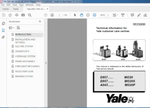
Yale Forklift B287 (MPE060VG, MPE080VG) Service Manual – PDF DOWNLOAD
$30.95
Yale Forklift B287 (MPE060VG, MPE080VG) Service Manual – PDF DOWNLOAD
Description
FILE DETAILS:
Yale Forklift B287 (MPE060VG, MPE080VG) Service Manual – PDF DOWNLOAD
Pages : 598
Downloadable : Yes
File Type : PDF
IMAGES PREVIEW OF THE MANUAL:
TABLE OF CONTENTS:
Yale Forklift B287 (MPE060VG, MPE080VG) Service Manual – PDF DOWNLOAD
524150797-8000YRM0231-(02-2023)-US-EN 1
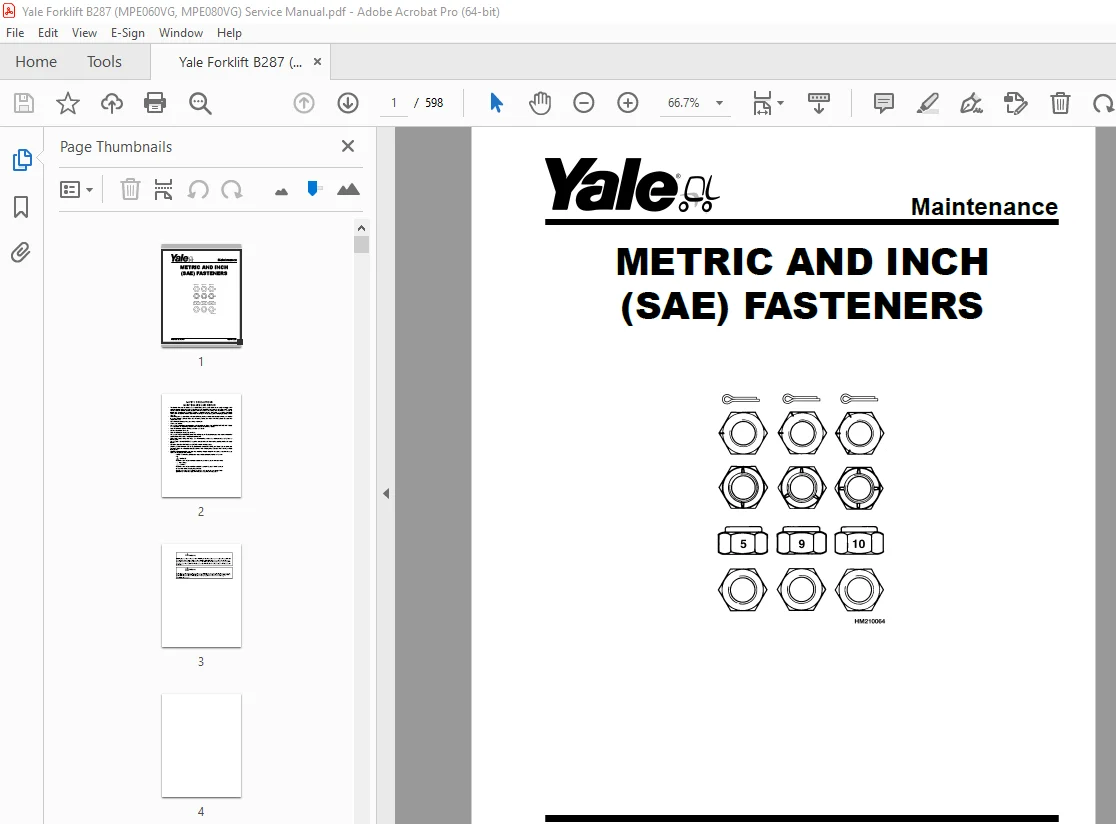
General 7
Threaded Fasteners 7
Nomenclature, Threads 7
Strength Identification 8
Cotter (Split) Pins 9
Fastener Torque Tables 14
Conversion Table 16
524150797-8000YRM0231-(03-2020)-US-EN 23
General 27
Threaded Fasteners 27
Nomenclature, Threads 27
Strength Identification 28
Cotter (Split) Pins 29
Fastener Torque Tables 34
Conversion Table 36
524158040-2240YRM0001-(01-2023)-US-EN 43
General 49
Battery Type 49
Lead-Acid Batteries 49
Lithium-Ion Batteries 50
Specific Gravity 50
Chemical Reaction in a Cell 50
Electrical Terms 52
Battery Selection 53
Battery Voltage 54
Battery as a Counterweight 54
Battery Ratings 54
Kilowatt-Hours 54
Battery Maintenance 55
Safety Procedures 55
Maintenance Records 55
New Battery 55
Cleaning Battery 56
Adding Water to Battery 58
Hydrometer 58
Battery Temperature 59
Charging Battery 60
Types of Battery Charges 61
Methods of Charging 62
Troubleshooting Charger 63
Knowing When Battery Is Fully Charged 63
Where to Charge Batteries 63
Equipment Needed 63
Battery Connectors 64
Battery Care 64
Troubleshooting 66
524158040-2240YRM0001-(03-2020)-US-EN 71
General 75
Battery Type 75
Lead-Acid Batteries 75
Lithium-Ion Batteries 76
Specific Gravity 76
Chemical Reaction in a Cell 76
Electrical Terms 78
Battery Selection 78
Battery Voltage 79
Battery as a Counterweight 80
Battery Ratings 80
Kilowatt-Hours 80
Battery Maintenance 80
Safety Procedures 80
Maintenance Records 81
New Battery 81
Cleaning Battery 81
Adding Water to Battery 83
Hydrometer 84
Battery Temperature 85
Charging Battery 86
Types of Battery Charges 86
Methods of Charging 88
Troubleshooting Charger 88
Knowing When Battery Is Fully Charged 89
Where to Charge Batteries 89
Equipment Needed 89
Battery Connectors 90
Battery Care 90
Troubleshooting 92
524164715-0630YRM0961-(03-2022)-US-EN 97
General 105
Check Oil Level 106
Change Gear Oil MTR005-007-F, MPE060-080-F, MPC060-080-F, MPE060-VG, MPE080-VG, MPE060VH, and MPE080VH 107
Drive Tire 107
Remove 107
Install 107
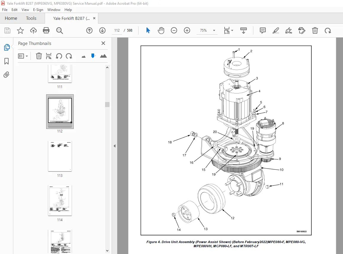
Master Drive Unit 108
Remove 108
Disassemble 115
Remove Drive Axle Group 115
Remove Upper Housing Group 116
Remove Pinion Group 116
Install 118
Troubleshooting 120
524164715-0630YRM0961-(12-2018)-US-EN 123
General 131
Check Oil Level 132
Change Gear Oil MTR005-007-F, MPE060-080-F, MPC060-080-F, MPE060-VG, MPE080-VG, MPE060VH, and MPE080VH 133
Drive Tire 133
Remove 133
Install 133
Master Drive Unit 133
Remove 133
Disassemble 140
Remove Drive Axle Group 140
Remove Upper Housing Group 140
Remove Pinion Group 140
Install 143
Troubleshooting 145
524274699-0620YRM1283-(12-2018)-US-EN 149
General 153
Accessing the Drive Unit Compartment 153
MPE060VG and MPE080VGMPE060VH and MPE080VH 153
MPC060/080-F and MTR005/007-F 154
Special Precautions 156
Discharging the Capacitors 156
Description 158
AC Motor Repair 158
Remove 158
Disassemble 159
Inspect 161
Assemble 161
Install 161
Troubleshooting 162
550073166-0620YRM1621-(12-2018)-US-EN 167
General 171
Special Precautions 171
Discharging the Capacitors 171
Traction Motor Repair 171
Remove 172
Disassemble 174
Clean/Inspect 178
Assemble 179
Install 180
Hydraulic Motor Repair 181
Disassemble 181
Inspect 183
Assemble 184
Special Tools 185
Tool Chart 185
Troubleshooting 186
550073167-0630YRM1609-(03-2021)-US-EN 191
Master Drive Unit 195
General 195
Description 195
Maintenance 196
Changing the Oil 196
Remove 196
Clean and Inspect 201
Install 204
Troubleshooting 205
550090075-8000YRM1643-(03-2018)-US-EN 209
550090078-8000YRM1644-(01-2016)-US-EN 237
General 241
How to Move a Disabled Truck 241
How to Tow the Lift Truck 242
How to Put a Lift Truck on Blocks 243
How to Raise Drive/Steer Tire 243
How to Raise Load Wheels 245
Accessing the Drive Unit Compartment 245
Special Precautions 247
Discharging the Capacitors 247
Welding Repairs 248
Maintenance Schedule 248
Maintenance Procedures Every 8 Hours or Daily 252
Checks With Key Switch Turned OFF 252
Battery 252
Hydraulic Leaks 253
Drive Tire, Load Wheels, Casters, and Frame 253
Checks With Key Switch Turned ON 254
Operation 254
Maintenance Procedures Every 250 Hours or Every 6 Weeks 256
Caster Lubrication 256
Caster Lubrication (MPE060-F and MPE060-VG) 257
Maintenance Procedures Every 500 Hours or Every 3 Months 258
Hydraulic System 258
Hydraulic Oil 259
Hydraulic Reservoir Breather 259
Steering System 259
Power Assist Steering 259
Lift Linkage and Load Wheels 260
Casters 260
Caster Adjustment Check 260
Caster Adjust Heavy-Duty 260
Casters (MPE060-F and MPE060-VG) 261
Caster Shim Check 261
Caster Shim Adjust 262
Master Drive Unit 263
Change Gear Oil 263
Check Oil Level 263
Kordel MDU 264
Drive Tire Check 264
Maintenance Procedures Every 2000 Hours or Yearly 264
Lubrication 264
Repack Load Wheel Bearings 264
Repack Steer Bearings (Manual Steer Only) 264
Hydraulic System 265
Oil Change 265
Brake 265
Electrical 266
MDU 266
Oil Change (Carraro) 266
Oil Change (Kordel) 266
Battery Maintenance 267
How to Charge the Battery 267
Equalizing Charge 268
Normal Charge 268
How to Change the Battery 268
Changing Battery With Rollers 270
Remove 270
Install 270
Transporting 270
Loading 271
Unloading 271
Preparation for Storage 272
Short-Term Storage (1 to 6 months) 272
Long-Term Storage (6 months or longer) 272
Preparation for Use 272
Preparation After Shipment 272
Preparation After Storage 272
550091255-0100YRM1636-(02-2017)-US-EN 275
General 279
Frame Separation and Assembly 279
Disassemble 280
Assemble 280
Painting Instructions 281
Label Replacement 281
550091256-1600YRM1637-(02-2017)-US-EN 285
General 289
Accessing the Drive Unit Compartment 289
Special Precautions 290
Electromagnetic Shield 290
Calibration 291
Power Assist Steering 291
Control Handle 292
Control Handle Head 292
Control Handle 292
Standard Steering 292
Remove 293
Install 293
Power Assist Steering 295
Remove 295
Install 296
Gas Spring 297
Discharging the Gas Spring 297
Remove 297
Install 298
Articulating Shaft and Pinions (EPAS) 298
Remove 299
Pinion Repair 300
Upper Pinion 300
Lower Pinion 301
Install 302
Steer Motor Assembly 302
Repair 302
Steer Motor, Replace 303
Steer Motor Gear, Replace 304
Gearbox/Complete Assembly, Replace 304
Steer Support Assembly 305
Standard Steering 305
Remove (Complete Unit) 305
Disassemble 305
Assemble 307
Install (Complete Unit) 307
Power Assist Steering (Option) 308
Remove (Complete Unit) 308
Disassemble 308
Support Base 308
Steer Swivel 310
Assemble 310
Steer Swivel 310
Support Base 311
Install (Complete Unit) 312
Smart Coast Control (Option) 313
Disassemble 313
Assemble 315
Coast Control Adjustment Procedure 316
Troubleshooting 318
550091257-1800YRM1638-(10-2019)-US-EN 321
General 325
Accessing the Drive Unit Compartment 325
Description 326
Special Precautions 327
Brake Check 328
Brake Release 328
Brake Apply 329
Air Gap 329
Hold On Grade Test 331
Brake Assembly Repair 331
MPE060-F, MPE060-G, MPE060-VG and MPE060VH 331
Remove 331
Repair 333
Install 333
MPE080-VG and MPE080VH 333
Remove 333
Repair 335
Install 335
Troubleshooting 336
550091258-1900YRM1639-(12-2018)-US-EN 339
General 343
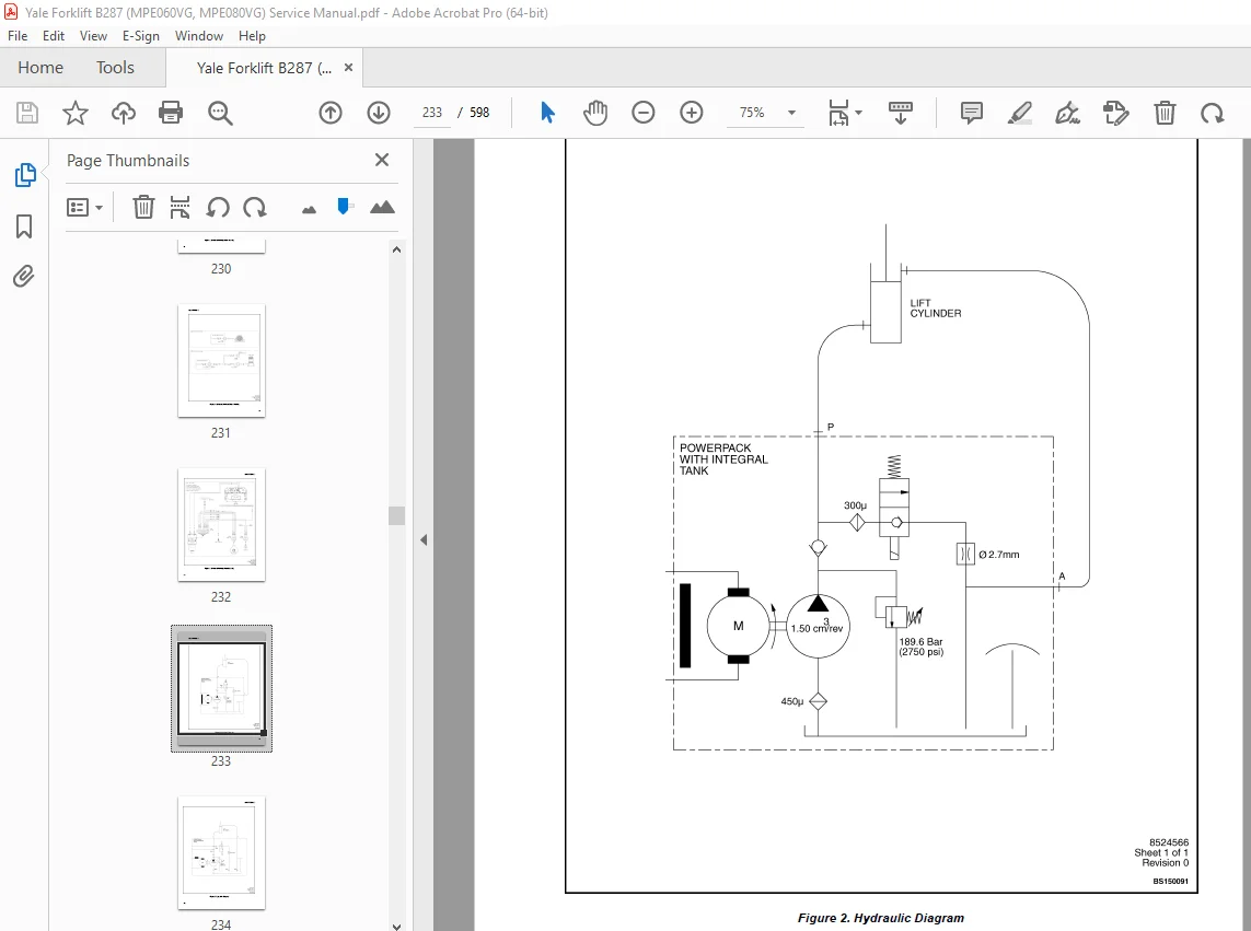
Description of Operation 343
Lifting a Load 344
Lowering a Load 348
Hydraulic Lines 348
Hydraulic Oil 348
Clean 348
Sound Level 348
Special Precautions 348
Hydraulic Reservoir 349
Drive Unit Compartment Covers 349
Lift Pump and Motor 351
General 351
Remove 351
Lift Pump and Motor Assembly 351
Disassemble 352
Remove Reservoir 352
Remove Pump Motor 354
Disassemble Pump 354
Assemble 354
Assemble Pump 354
Install Pump Motor 354
Install Reservoir to Pump 355
Install 355
Lift Pump and Motor Assembly 355
Valve Repair 356
Lowering Valve 356
Remove 356
Install 356
Relief Valve 357
Remove 357
Install 357
Check Valve 357
Remove 357
Install 358
Lift Cylinder 358
Remove 358
Disassemble 360
Assemble 360
Install 361
Relief Valve Pressure Check 361
Relief Valve Adjust 363
Troubleshooting 363
Lift Assemblies 363
Lift Cylinders 364
Lift Pump and Motor Assembly 365
550091259-2200YRM1658-(02-2017)-US-EN 369
General 373
Introduction 373
Description 373
Button Keypad 373
LED Indicator Lights 373
LCD Screen 373
Dash Display Menu Access 374
Menu Navigation 374
Dash Display Menu Operation 374
Nodes 374
Menu Structure 375
Supervisor-Level Menu 375
Hour Meters 376
H1 Truck Hours 376
H2 Traction Hours 376
H3 Pump Hours 376
H4 Steer Hours 376
H5 Odometer Hours 377
H10 Display Hours 377
H32 Combination Node Hours 377
H40 Steer Node Hours 377
Performance 377
Performance Level 1 378
P1 1 Forward 379
P1 2 Reverse 379
P1 3 Acceleration 379
P1 4 Plug 379
P1 5 Coast 379
P1 6 Lift Speed 379
P1 7 Lower Speed 379
P1 26 Pick Speed 379
P1 27 Pick Accel 379
P1 28 Pick Decel 380
P1 29 MIN Steer Assist F 380
P1 30 MIN Steer Assist R 380
P1 31 Max Steer Assist 380
Operator Passwords 380
Add Password 381
Delete Password 381
Edit Password 381
Operator Password 381
Clear Log 381
Operator Logs 382
Operator 1-150 382
Information 383
I1 Model 383
I3 Serial Number 383
I5 Truck Voltage 383
Software Versions 384
550091260-2200YRM1659-(02-2017)-US-EN 387
General 393
Introduction 393
Description 393
Button Keypad 393
LED Indicator Lights 393
LCD Screen 393
Dash Display Menu Access 394
Menu Navigation 394
Dash Display Menu Operation 394
Nodes 394
Menu Structure 395
Service-Level Menu 396
Hour Meters 397
H1 Truck Hours 398
H2 Traction Hours 398
H3 Pump Hours 398
H4 Steer Hours 398
H5 Odometer Hours 398
H10 Display Hours 398
H32 Combinatin Node Hours 398
H40 Steer Node Hours 398
Performance 398
Performance Level 1 399
P1 1 Forward 399
P1 2 Reverse 399
P1 3 Acceleration 399
P1 4 Plug 399
P1 5 Coast 399
P1 6 Lift Speed 400
P1 7 Lower Speed 400
Operator Passwords 400
Add Password 401
Delete Password 401
Edit Password 401
Operator Password 401
Clear Log 401
Operator Logs 401
Operator 1-150 401
Information 402
I1 Model 402
I3 Serial Number 402
I5 Truck Voltage 402
Settings 403
S1 Metric 405
S2 User Performance 405
S3 Timeout 405
S4 Battery Type 405
S5 BDI Startup Full 405
S6 BDI Full 405
S7 BDI Empty 405
S8 BDI Reset 405
S9 Lift Interrupt 405
S10 Audible Warning 405
S11 Visual Warning 406
S12 Checklist 406
S13 Maint Reminder 406
S14 Restore Default 406
S15 Truck Lockout 406
S61 Extended Shift 406
S63 Walk Speed Accel 406
S64 Walk Speed Decel 407
S65 Pick Accel 407
S66 Pick Decel 407
S67 Min Steer Assist F 407
S68 Min Steer Assist R 407
Software Versions 407
Error Log 408
(E1) Error Log 1 409
Error 1 1 (E1 1) 409
Error 1 2 (E1 2) 409
Error 1 3 (E1 3) 409
Error 1 4 (E1 4) 409
Diagnostics 410
Diagnostics 410
D1 Status 410
D2 Input 410
D3 Output 410
D1 Status 410
D1 1 CAN 411
D1 2 Contactor 411
D1 3 Full Traction 411
D1 4 Limp Traction 411
D1 5 Steering 411
D1 6 Lift 411
D1 7 Lower 411
D1 11 Emergency Reverse 411
D1 12 Pick Function 412
D2 Inputs 412
D2 10 Display 412
D2 10 1 Bus Error 413
D2 10 2 Bus Max Error 413
D2 10 32 Combination Controller 413
D2 10 40 Steer 413
D2 10 60 CTRL Hand 413
D2 32 Combination Controller 413
D2 32 1 Target Speed 416
D2 32 2 Motor Speed 416
D2 32 3 Motor Encoder 416
D2 32 4 Controller Temperature 416
D2 32 5 Motor Temperature 416
D2 32 6 Motor Current 416
D2 32 7 Cap Voltage 417
D2 32 8 Cap Maximum Voltage 417
D2 32 9 Cap Minimum Voltage 417
D2 32 10 Key Voltage 417
D2 32 11 Key Max Voltage 417
D2 32 12 Key Minimum Voltage 417
D2 32 16 MC Connct 417
D2 32 17 MC Current 417
D2 32 18 Horn Switch 417
D2 32 19 Brake Switch 417
D2 32 20 Horn Connect 417
D2 32 22 Pump Current 417
D2 32 22 Rabbit Switch 417
D2 32 23 ACC Switch 417
D2 32 24 Donut Switch 417
D2 32 25 Belly Switch NC 417
D2 32 26 Regen Switch 417
D2 32 27 Lift Switch 418
D2 32 28 Lower Switch 418
D2 32 29 Steer Status 418
D2 32 31 Load Hold Connect 418
D2 32 32 Load Hold Current 418
D2 32 33 SOC 418
D2 40 Steer 418
D2 40 5 Cont Temp 418
D2 40 15 Torque 1 Switch 418
D2 40 17 Center Prox SW 418
D2 40 19 Steer Angle 419
D2 60 Control Handle 419
D2 60 1 Horn Switch 420
D2 60 2 Lift Switch 420
D2 60 3 Lift Switch 2 420
D2 60 4 Lower Switch 420
D2 60 5 Lower Switch 2 420
D2 60 6 Pick Switch 420
D2 60 7 Pick Switch 2 420
D2 60 8 Belly Switch NO 420
D2 60 9 Regen Switch 420
D2 60 10 Tilt Up SW 420
D2 60 11 Tilt Down SW 421
D2 50 14 4th Aux IN SW 421
D2 50 15 4th Aux OUT SW 421
D2 60 19 Trac Input 421
D2 60 20 Lift/Lower Input 421
D3 Output 421
D3 10 Display 421
D3 10 10 Display Com 421
D3 10 32 Combination Com 421
D3 10 40 Steer Com 422
D3 10 60 Handle Com 422
D3 32 Traction 422
D3 32 1 U-V Line DC Curr 423
D3 32 2 U-W Line DC Curr 423
D3 32 3 V-W Line DC Curr 423
D3 32 6 Pump DC Current 423
D3 32 7 Pump Motor Short 423
D3 32 8 ACC Coil 423
D3 32 9 Load Hold 423
D3 32 10 Backup Alarm 423
D3 32 11 Strobe 423
D3 32 12 Horn 423
Calibration 423
424
C4 Throttle 424
550091261-2200YRM1640-(02-2017)-US-EN 427
General 431
Accessing the Drive Unit Compartment 432
Special Precautions 433
Discharging the Internal Capacitors 433
Electromagnetic Shield 433
Electrical System Checks 434
Safety Precautions 434
Calibration 437
Power Assist Steering Sensor 437
Repairs 437
Controller, Replace 438
Remove 438
Install 438
Contactor Coil, Check 439
Fuses 439
Horn 440
Replace 440
Brake Switch Operation 440
Brake and Interlock Switches 440
Standard Steering 441
Power Assist Steering 442
Height Limit 442
Control Handle (Standard) 443
Disassemble 443
Assemble 443
Control Handle (HD Option) 444
Disassemble 445
Remove Top Cover 445
Remove Function Switches 445
Remove Throttle Sensor Assembly 445
Remove Handle Shaft Assembly 446
Remove Quick Pick Switches 446
Remove the Coast Control Switches 447
Assemble 447
Install the Coast Control Switches 447
Install Quick Pick Switches 447
Install Handle Shaft Assembly 447
Install Throttle Sensor Assembly 448
Install Function Switches 448
Install Top Cover 448
Control Module 449
Check 449
Remove 451
Install 451
Proximity Switch (Power Assist Steering) 452
Remove 452
Install 452
Remote Control Box Switches 453
Remove 453
Install 453
Troubleshooting 453
550091262-4000YRM1641-(05-2019)-US-EN 457
General 461
Description of Operation 461
Load Wheel 461
Remove 461
Install 463
Casters 463
Caster Adjustment Check 463
Caster Adjust Heavy-Duty 464
Caster Replacement 464
Disassemble 465
Heavy-Duty 465
Assemble 466
Heavy-Duty 466
Rear Link and Load Wheel 466
Remove 466
Install 468
Pull Rod 469
Remove 470
End Replacement 470
Install 470
Fork Height Adjustment 471
Heavy Duty Trucks 471
Light Duty Trucks 472
Rocker Arm 473
Remove 473
Install 474
Upper Link 474
Remove 475
Install 475
Entry Rollers 476
Replacement 476
Troubleshooting 476
550091262-4000YRM1641-(08-2022)-US-EN 479
General 483
Description of Operation 483
Load Wheel 483
Remove 483
Install 485
Casters 486
Caster Adjustment Check 486
Caster Adjust Heavy-Duty 486
Caster Replacement 487
Disassemble 487
Heavy-Duty 487
Assemble 488
Heavy-Duty 488
Rear Link and Load Wheel 489
Remove 489
Install 491
Pull Rod 493
Remove 493
End Replacement 493
Install 493
Fork Height Adjustment 494
Heavy Duty Trucks 494
Light Duty Trucks 495
Rocker Arm 497
Remove 497
Install 498
Upper Link 499
Remove 499
Install 499
Entry Rollers 501
Replacement 501
Troubleshooting 502
550091263-8000YRM1642-(01-2016)-US-EN 505
Hydraulic System 509
Hydraulic Oils 509
Gear Oils 509
Grease 509
Truck Weight 510
Tire Sizes 510
Torque Specifications 511
Caster Assembly 511
Drive Wheel Assembly 511
Master Drive Unit 511
Standard Steering 511
Power Assist Steering 511
Brake 512
Electrical 512
Lift Mechanism 512
Hydraulics 512
Battery Specifications 512
550091264-9000YRM1660-(02-2017)-US-EN 517
SECTION 9030 ELECTRICAL SYSTEM 521
Group 03 – General Maintenance and Diagnostic Data 523
Group 20 – Diagnostic Trouble Codes 533
S.V 06/24