Yale Forklift B295 (NDR030DB, NR040DB, NR035DB) Service Manual PDF
$33.95
Yale Forklift B295 (NDR030DB, NR040DB, NR035DB) Service Manual – PDF DOWNLOAD
Description
Yale Forklift B295 (NDR030DB, NR040DB, NR035DB) Service Manual – PDF DOWNLOAD
FILE DETAILS:
Yale Forklift B295 (NDR030DB, NR040DB, NR035DB) Service Manual – PDF DOWNLOAD
Language : English
Pages : 1454
Downloadable : Yes
File Type : PDF
IMAGES PREVIEW OF THE MANUAL:
TABLE OF CONTENTS:
Yale Forklift B295 (NDR030DB, NR040DB, NR035DB) Service Manual – PDF DOWNLOAD
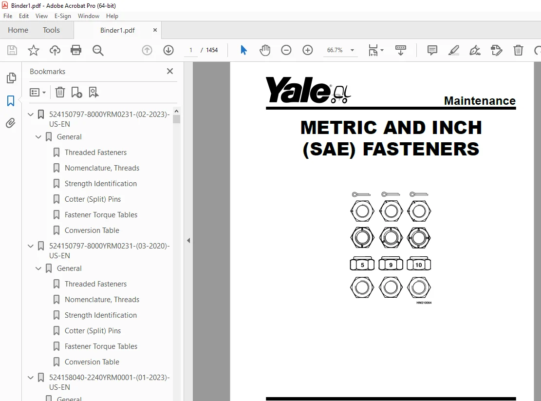
524150797-8000YRM0231-(02-2023)-US-EN 1
General 7
Threaded Fasteners 7
Nomenclature, Threads 7
Strength Identification 8
Cotter (Split) Pins 9
Fastener Torque Tables 14
Conversion Table 16
524150797-8000YRM0231-(03-2020)-US-EN 23
General 27
Threaded Fasteners 27
Nomenclature, Threads 27
Strength Identification 28
Cotter (Split) Pins 29
Fastener Torque Tables 34
Conversion Table 36
524158040-2240YRM0001-(01-2023)-US-EN 43
General 49
Battery Type 49
Lead-Acid Batteries 49
Lithium-Ion Batteries 50
Specific Gravity 50
Chemical Reaction in a Cell 50
Electrical Terms 52
Battery Selection 53
Battery Voltage 54
Battery as a Counterweight 54
Battery Ratings 54
Kilowatt-Hours 54
Battery Maintenance 55
Safety Procedures 55
Maintenance Records 55
New Battery 55
Cleaning Battery 56
Adding Water to Battery 58
Hydrometer 58
Battery Temperature 59
Charging Battery 60
Types of Battery Charges 61
Methods of Charging 62
Troubleshooting Charger 63
Knowing When Battery Is Fully Charged 63
Where to Charge Batteries 63
Equipment Needed 63
Battery Connectors 64
Battery Care 64
Troubleshooting 66
524158040-2240YRM0001-(03-2020)-US-EN 71
General 75
Battery Type 75
Lead-Acid Batteries 75
Lithium-Ion Batteries 76
Specific Gravity 76
Chemical Reaction in a Cell 76
Electrical Terms 78
Battery Selection 78
Battery Voltage 79
Battery as a Counterweight 80
Battery Ratings 80
Kilowatt-Hours 80
Battery Maintenance 80
Safety Procedures 80
Maintenance Records 81
New Battery 81
Cleaning Battery 81
Adding Water to Battery 83
Hydrometer 84
Battery Temperature 85
Charging Battery 86
Types of Battery Charges 86
Methods of Charging 88
Troubleshooting Charger 88
Knowing When Battery Is Fully Charged 89
Where to Charge Batteries 89
Equipment Needed 89
Battery Connectors 90
Battery Care 90
Troubleshooting 92
524164473-4000YRM0481-(08-2016)-US-EN 97
General 101
Description 101
Lowering Control Valve 102
Main Cylinder Repair 103
Disassemble 104
Assemble 105
Free-Lift Cylinder Repair 106
Disassemble 106
Assemble 106
Troubleshooting 108
524223769-2200YRM1128-(01-2023)-US-EN 111
Series Code / Model Designation Reference Table 119
General 121
Deutsch Crimping Tool 122
How to Strip a Wire for Use With Deutsch Crimping Tool 122
How to Crimp With the Deutsch Crimping Tool 123
Calibration Test for the Deutsch Crimping Tool 125
Deutsch Connectors 127
DT, DTM, and DTP Series Connectors 127
HD Series Connectors 170
Metri-Pack Connectors 192
Remove and Install 192
Micro-Pack Connectors 195
Weather-Pack Connectors 196
AMPSEAL Crimping Tools 198
AMP Hand Crimping Tool With Certi-Crimp 198
Description 198
Stripping Wire for Use with AMP Hand Crimping Tool 199
Insulation Crimp Adjustment 200
Maintenance and Inspection for AMP Hand Crimping Tool 200
AMP Hand Crimping Tool 200
Crimp Height Inspection 200
How to use AMP Hand Crimping Tool 201
AMP Pro-Crimper II Tool 201
Description 201
Remove and Install Die Set and Locator Assembly 202
Stripping Wire for Use With AMP PRO-CRIMPER II Tool 202
Contact Support Adjustment 203
Crimp Height Adjustment 204
Maintenance and Inspection Procedures 204
PRO-CRIMPER II Tool 204
Crimp Height Inspection 204
How to Use AMP PRO-CRIMPER II Tool 205
AMPSEAL Connector Assemblies 206
Description for Plug Connector Assembly 206
Seal Plug 207
Contact Crimping 207
Description for Plug Connector and Header Assembly 212
Voltage Reading 215
Seal Plug 215
Contact Crimping 215
AMP Superseal 1 5 Crimping Tools 222
Mini Mic Receptacle and Tab Contacts 222
Description 222
Crimping Conditions and Measurements 222
Insertion of Rubber Seal on Cable 224
AMP Hand Application Tool 229
Description 229
Maintenance and Inspection 229
Crimp Height Inspection 229
Crimp Height Adjustment 230
How to Use AMP Hand Application Tool 230
AMP Pro-Crimper II Tool 231
Description 231
Remove and Install Die Set and Locator Assembly 231
Adjustments 232
Contact Support 232
Crimp Height 233
Inspections and Maintenance 234
Crimp Height Inspection 234
Visual Inspection 234
Maintenance 235
How to Use Pro-Crimper II Tool 235
AMP Superseal 1 5 Connector Assemblies 236
Description 236
Repair and Maintenance 243
Panel Mount Option 243
AMP Fastin-Faston Hand Tools 244
Description – AMP Double Action Hand Tool 244
Maintenance and Inspection Procedures 244
Daily Maintenance 244
Periodic Tool Inspection 245
Lubrication 245
Visual Inspection 245
Crimp Height Inspection 245
Certi-Crimp Ratchet Inspection 246
How to Use AMP Double Action Hand Tool 247
Description – AMP Extraction Tool 248
Maintenance and Inspection 249
How to Use AMP Extraction Tool 249
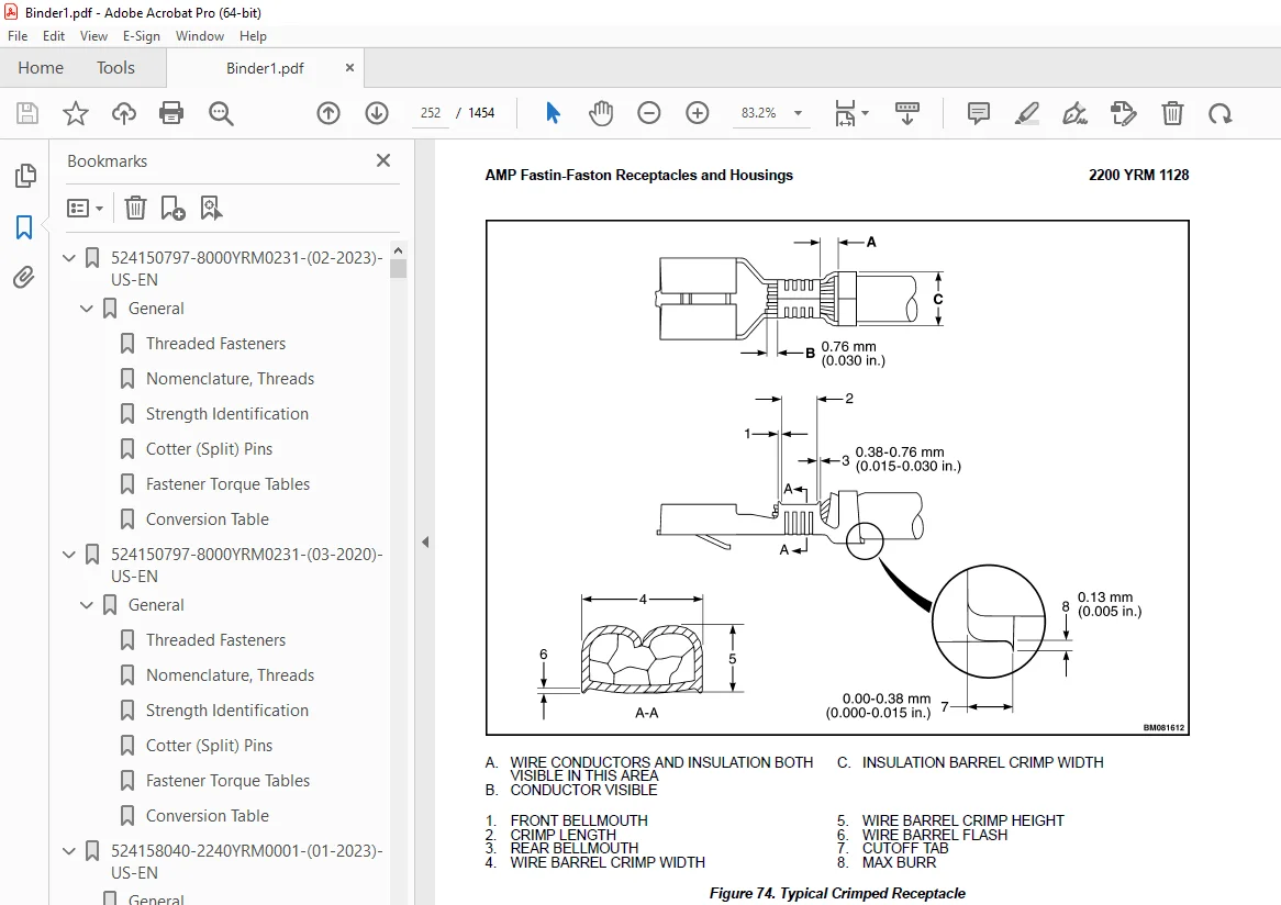
AMP Fastin-Faston Receptacles and Housings 251
Description 251
Wire Repair 259
Wire Splicing Requirements 259
Deutsch Jiffy Splice 260
Twisted/Shielded Cable and Leads Repair 266
Special Tools 268
524223769-2200YRM1128-(07-2020)-US-EN 277
Series Code / Model Designation Reference Table 283
General 286
Deutsch Crimping Tool 286
How to Strip a Wire for Use With Deutsch Crimping Tool 286
How to Crimp With the Deutsch Crimping Tool 287
Calibration Test for the Deutsch Crimping Tool 289
Deutsch Connectors 291
DT, DTM, and DTP Series Connectors 291
HD Series Connectors 333
Metri-Pack Connectors 356
Remove and Install 356
Micro-Pack Connectors 358
Weather-Pack Connectors 359
AMPSEAL Crimping Tools 361
AMP Hand Crimping Tool With Certi-Crimp 361
Description 361
Stripping Wire for Use with AMP Hand Crimping Tool 361
Insulation Crimp Adjustment 362
Maintenance and Inspection for AMP Hand Crimping Tool 362
AMP Hand Crimping Tool 362
Crimp Height Inspection 362
How to use AMP Hand Crimping Tool 363
AMP Pro-Crimper II Tool 363
Description 363
Remove and Install Die Set and Locator Assembly 364
Stripping Wire for Use With AMP PRO-CRIMPER II Tool 365
Contact Support Adjustment 365
Crimp Height Adjustment 366
Maintenance and Inspection Procedures 366
PRO-CRIMPER II Tool 366
Crimp Height Inspection 366
How to Use AMP PRO-CRIMPER II Tool 367
AMPSEAL Connector Assemblies 368
Description for Plug Connector Assembly 368
Seal Plug 369
Contact Crimping 369
Description for Plug Connector and Header Assembly 374
Voltage Reading 376
Seal Plug 376
Contact Crimping 376
AMP Superseal 1 5 Crimping Tools 383
Mini Mic Receptacle and Tab Contacts 383
Description 383
Crimping Conditions and Measurements 383
Insertion of Rubber Seal on Cable 385
AMP Hand Application Tool 390
Description 390
Maintenance and Inspection 390
Crimp Height Inspection 390
Crimp Height Adjustment 391
How to Use AMP Hand Application Tool 391
AMP Pro-Crimper II Tool 392
Description 392
Remove and Install Die Set and Locator Assembly 393
Adjustments 393
Contact Support 393
Crimp Height 394
Inspections and Maintenance 395
Crimp Height Inspection 395
Visual Inspection 395
Maintenance 396
How to Use Pro-Crimper II Tool 396
AMP Superseal 1 5 Connector Assemblies 397
Description 397
Repair and Maintenance 404
Panel Mount Option 404
AMP Fastin-Faston Hand Tools 405
Description – AMP Double Action Hand Tool 405
Maintenance and Inspection Procedures 405
Daily Maintenance 405
Periodic Tool Inspection 406
Lubrication 406
Visual Inspection 406
Crimp Height Inspection 406
Certi-Crimp Ratchet Inspection 407
How to Use AMP Double Action Hand Tool 408
Description – AMP Extraction Tool 409
Maintenance and Inspection 409
How to Use AMP Extraction Tool 410
AMP Fastin-Faston Receptacles and Housings 411
Description 411
Wire Repair 418
Wire Splicing Requirements 418
Deutsch Jiffy Splice 419
Twisted/Shielded Cable and Leads Repair 424
Special Tools 427
524233335-1800YRM1188-(01-2016)-US-EN 435
Introduction 439
General 439
Discharging the Capacitors 439
Electric Brake 440
Air Gap 441
Remove 442
Install 443
Troubleshooting 444
524233341-4000YRM1194-(01-2016)-US-EN 449
General 453
Safety Procedures When Working Near Mast 454
Mast Weldments 456
Reach Carriage Assembly 456
Three-Stage Mast 458
Description 458
Operation 459
524233342-4000YRM1195-(07-2019)-US-EN 463
General 467
Safety Procedures When Working Near Mast 467
Load Backrest 468
Remove 468
Install 468
Forks 468
Remove 469
Install 469
Checks, Lift Truck Models NR045EA, NDR035EA (C861); NR035EA, NR040EA, NDR030EA (D815); NR035DA, NR040DA, NDR030DA (A295) 469
Checks, Lift Truck Models NR045EB, NDR035EB (D861); NR035EB, NR040EB, NDR030EB (E815); NR035DB, NR040DB, NDR030DB (B295) 470
Sheaves 472
Hydraulic System 475
Hydraulic Oil 477
Drain 477
Cylinder Identification 479
Fill 480
Main Lift Cylinders 481
Free-Lift Cylinders 481
Reach Carriage Assembly 482
Remove 482
Install 484
Load Rollers 485
Mast 485
Reach Assembly 487
Load Rollers 487
Side Rollers 487
Mast 488
Remove 488
Disassemble 489
Clean and Inspect 490
Assemble 491
Install 493
Lift Cylinders 494
Main Lift Cylinders 494
Remove 494
Install 497
Free-Lift Cylinder 498
Remove 498
Install 499
Lift Chains 500
Clean and Inspect 500
Mast Adjustments 501
General 501
Mast Back Angle Adjustment 501
Load Rollers Adjustment 502
Reach Carriage Assembly 502
Adjust Wear Plugs – Mast 503
Adjust Main-Lift Chains 505
Adjust Free-Lift Chain 505
Adjust Wear Strips 507
Mast Racking 508
Proximity Switches 509
Replace 510
Free-Lift Proximity Switch 510
Load Lowering Proximity Switch (Optional) 511
Adjust 511
Mast Operation Check 511
Lift System Leak Check 512
Lift Cylinder Leak Check 512
Tilt Cylinder Leak Check 512
524233343-4500YRM1196-(01-2016)-US-EN 515
General 519
Safety Procedures When Working Near Mast 519
Description 520
Repair – General 522
Load Backrest 522
Remove 522
Install 522
Forks 523
Replacement 523
Remove 523
Install 523
Reach Carriage Assembly 524
Remove 524
Inspect 525
Install 526
Reach Carriage Assembly Repair 526
Load Rollers Repair 527
Side Rollers Repair (6 9 Mast Only) (NDR030DA and NR035/040DA) 528
Reach Assembly Front Frame 529
Remove 529
Disassemble (With Sideshift) 530
Disassemble (Without Sideshift) 532
Clean and Inspect 533
Assemble (With Sideshift) 533
Assemble (Without Sideshift) 533
Install 534
Single-Reach Scissor Arms 534
Remove and Disassemble 534
Clean and Inspect 538
Assemble and Install 538
Double-Reach Scissor Arms 540
Disassemble 540
Clean and Inspect 544
Assemble 544
Rear Frame Assembly 547
Remove 547
Disassemble 549
Clean and Inspect 550
Assemble 550
Install 550
Reach Cylinders 552
Remove 552
Disassemble 553
Clean and Inspect 554
Assemble 554
Install 555
Tilt Cylinder 555
Remove 555
Clean, Inspect, and Repair 556
Install 557
Sideshift Cylinder 557
Repair 557
Front Selector Valve 558
Rear Selector Valve 559
Reach Assembly Adjustments 559
Check Adjustment 560
Adjust Side Rollers and Load Rollers 561
Adjust Reach Cylinders 562
Lift Chains 563
Inspect 563
Clean and Lubricate 564
Adjust Main-Lift Chains 564
Adjust Free-Lift Chains 564
Specifications 565
Troubleshooting 568
524287793-1900YRM1307-(11-2015)-US-EN 573
General 577
Discharging the Capacitors 580
Description 580
Control Handle (A295) 580
Sidestance Control Handle
581
Fore/Aft Stance 582
Control Handle (B295) 582
Sidestance Control Handle 583
Fore/Aft Stance 584
Maintenance 584
Oil Level and Leaks 585
Operation 585
Oil Change 585
Drain 585
Cylinder Identification 587
Fill 588
Main Lift Cylinders 589
Free-Lift Cylinders 589
Breather Cap 590
Inspect 590
Oil Filter 590
Change 590
Oil Strainer 591
Check 591
Hydraulic System 592
General 592
Cleaning 592
Noise Levels 592
Hoses 593
Fittings 595
Lift Pump and Motor 595
Complete Unit 595
Remove 595
Install 596
Lift Pump 597
Remove 597
Disassemble 598
Assemble 598
Install 599
Main Control Valve 600
Description 600
Check 600
Tilt Valve Test 600
Remove 600
Disassemble 601
Clean 601
Assemble 602
Install 602
Manual Lowering 603
Auxiliary Hydraulics 604
Front Selector Valve 604
Rear Selector Valve 605
Hydraulic Tank 605
Remove 606
Disassemble 607
Breather Assembly 608
Filter Assembly 609
Low Oil Indicator Switch 610
Tank Fittings 610
Clean and Inspect 610
Assemble 611
Breather Assembly 611
Filter Assembly 611
Low Oil Indicator Switch 611
Tank Fittings 611
Install 611
Specifications 612
Troubleshooting 613
550072990-8000YRM1619-(09-2019)-US-EN 617
Schematics 621
550072991-8000YRM1617-(02-2018)-US-EN 651
General 655
Removing Covers 656
Front Frame Panel (Left and Right) 656
Operator Compartment Cover 656
Drive Unit Compartment Door 657
Caster Wheel Cover 657
Discharging the Capacitors 657
How to Move Disabled Truck 658
How to Tow Lift Truck 658
How to Put Lift Truck on Blocks 659
How to Raise Load Wheels 659
How to Raise the Drive Tire End 659
How to Raise the Entire Lift Truck 660
Manual Lowering Valve 661
NDR030/035EB and NR030/040/045EB 661
NDR030DB and NR035/040DB 661
Transporting 662
Loading 662
Unloading 663
Preparation for Use 663
Preparation After Shipment 663
Preparation After Storage 663
Safety Procedures When Working Near Mast 663
Maintenance Schedule 665
Maintenance Procedures Every 8 Hours or Daily 671
Checks With Key Switch Turned OFF 672
Battery 672
Tires and Wheels 673
Frame and Load Wheels 673
Safety Labels 673
Overhead Guard 673
Forks Check 674
Lift Chain Check 675
Mast Check 676
Reach, Tilt, and Sideshift 676
Checks With Key Switch Turned ON 676
Operation 676
Hydraulic System 677
Dash Display 677
Lift System Operation 678
Multifunction Control Handle 679
Brake 680
Steering System 680
Maintenance Procedures Every500 Hours or 3 Months 680
Master Drive Unit 680
Hydraulic System 680
Hydraulic Filter Element Change 682
Caster Adjustment 682
Elastomer Spring Adjustment 683
Spring Pack Replacement 684
Remove Spring Assembly 684
Replace Spring Pack 684
Install Spring Assembly 685
Drive Tire Check 685
Lift System Operation 686
Forks Check 686
Mast 686
Lift Chains 687
Other Lubrication 688
Maintenance Procedures Every 2000 Hours or Yearly 688
Brakes 688
Check 688
Electric System 688
Main Contactor 688
Inspect 688
Forks, Check 689
Hydraulic System 689
Drain 689
Cylinder Identification 691
Fill 692
Main Lift Cylinders 693
Free-Lift Cylinders 693
Hydraulic Filter Change 694
Check Hydraulic Strainer 695
Lift and Tilt System Leaks Check 695
Lift System 695
Tilt System 696
Battery Maintenance 696
How to Charge Battery 696
How to Change Battery 698
Tires and Wheels 700
Drive Tire 700
How to Change Drive Tire 701
Tandem Load Wheels 702
Caster Wheels 702
Remove 702
Install 703
Preparation for Storage 704
Short-Term Storage (1 to 6 months) 704
Long-Term Storage (6 months or longer) 704
550073166-0620YRM1621-(12-2018)-US-EN 707
General 711
Special Precautions 711
Discharging the Capacitors 711
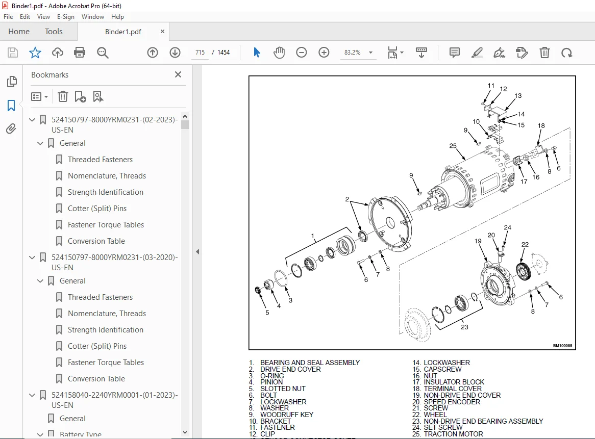
Traction Motor Repair 711
Remove 712
Disassemble 714
Clean/Inspect 718
Assemble 719
Install 720
Hydraulic Motor Repair 721
Disassemble 721
Inspect 723
Assemble 724
Special Tools 725
Tool Chart 725
Troubleshooting 726
550073167-0630YRM1609-(03-2021)-US-EN 731
Master Drive Unit 735
General 735
Description 735
Maintenance 736
Changing the Oil 736
Remove 736
Clean and Inspect 741
Install 744
Troubleshooting 745
550073168-1600YRM1610-(04-2014)-US-EN 749
550073169-0100YRM1615-(01-2016)-US-EN 797
General 801
Description 802
Repairs – General 802
Covers, Panels, and Plates 802
Front Frame Panel (Left and Right) 802
Operator Compartment Cover 803
Drive Unit Compartment Door 803
Door Pad 803
Operator Back Pad 804
Side-Stance Models 804
Forward-Stance Models 804
Operator Front Pad 804
Caster Wheel Cover 804
Load Wheels 805
Remove 805
Install 806
Overhead Guard Replacement 807
Remove 812
Install 812
Front Lights 812
Bulb Replacement 812
Assembly Replacement 813
Rear Work and Caution Light 814
Caution Light 814
Painting Instructions 814
Safety Labels Replacement 816
550073170-1900YRM1616-(12-2018)-US-EN 823
General 827
Discharging the Capacitors 828
Description 828
Control Handle 829
Sidestance Control Handle 829
Fore/Aft Stance 830
Maintenance 830
Oil Level and Leaks 831
Operation 831
Oil Change 831
Drain 831
Cylinder Identification 833
Fill 834
Main Lift Cylinders 835
Free-Lift Cylinders 835
Breather Cap 836
Inspect 836
Oil Filter 837
Change 837
Oil Strainer 837
Check 837
Hydraulic System 837
General 838
Cleaning 838
Noise Levels 838
Hoses 838
Fittings 840
Lift Pump and Motor 840
Complete Unit 841
Remove 841
Install 842
Lift Pump 843
Components 844
Pressure Flange Fitting 844
Supply and Return Fittings 845
Manual Lowering Valve 845
Pressure Test Ports 845
Pressure Transducer 846
Relief Valve 848
Lowering Control Valve 848
Remove Pump 848
Install Pump 849
Auxiliary Hydraulics 849
Auxiliary Pump and Motor 850
Remove 850
Disassemble 851
Assemble 851
Install 852
Front Selector Valve 853
Rear Selector Valve 853
Hydraulic Tank 854
Remove 855
Disassemble 856
Breather Assembly 856
Filter Assembly 857
Tank Fittings 858
Clean and Inspect 858
Assemble 858
Breather Assembly 858
Filter Assembly 859
Tank Fittings 859
Install 860
Specifications 860
Troubleshooting 860
550073171-9000YRM1622-(01-2022)-US-EN 865
SECTION 9030 Electrical System 871
Group 03 – General Maintenance and Diagnostic Data 875
Group 20 – Diagnostic Trouble Codes 889
550073171-9000YRM1622-(10-2019)-US-EN 1063
SECTION 9030 Electrical System 1069
Group 03 – General Maintenance and Diagnostic Data 1073
Group 20 – Diagnostic Trouble Codes 1085
550073172-2200YRM1612-(07-2018)-US-EN 1259
General 1265
Discharging the Internal Capacitors 1266
Static Strap 1266
Inspect 1267
Replace 1267
Battery Connection 1267
Inspect 1267
Replacing Cables 1267
Key Switch 1268
Replace 1269
Major Electrical System Features 1270
Integrated System 1271
CANbus Advantages 1271
CANbus Communications 1271
Electric Steering / Steer Caster (Optional) 1271
Centering Proximity Sensor 1271
Traction 1272
CAN I/O 1272
Input Devices 1272
Output Devices 1272
Encoder Integrity 1272
Test Encoders 1272
Proximity Switches 1272
Key Switch 1273
Multifunction Displays 1273
BDI 1273
Speed 1273
Steer Angle 1273
Truck Hours 1273
Operational Mode 1274
Setup 1274
Setup Instructions 1274
ACE2 / ACE3 Traction and Hydraulic Controllers 1274
Normal Operation 1274
Display 1274
Password Access 1274
Startup Checklist 1274
Truck Operation Mode 1275
Diagnostics 1275
Calibrations 1275
AC Motor Controllers 1276
Controller Removal 1277
Install 1277
Low-Voltage Protection Function 1277
CDF File Installation Procedure 1278
Contactor and Electrical Panel Checks 1278
Fuses 1279
Contactors 1279
General 1279
Test 1280
Tips 1280
Disassemble and Assemble 1281
Instrument Panel Removal and Installation 1282
Key Switch Removal and Installation 1282
Remove 1282
Install 1282
Integrated Fuse Board (IFB) 1282
Replace 1283
Diodes 1284
Power Disconnect Switch 1285
Replace 1285
Side-Stance Controls 1287
Multifunction Control Handle 1287
Horn 1288
Inspection 1288
Remove 1289
Install 1291
Forward-Stance Controls 1291
Control Handle Functions 1291
Repair 1292
Aft Travel Control Handle Option 1293
Repair 1294
Aft Handle Sensor Adjustment 1295
Control Handle Disassembly and Repair 1295
Thumb Grip Pad Replacement 1296
Handle Grip and Switch Repairs 1297
Handle Grip Support Mounting 1297
Handle Disassembly 1298
Steering Handle 1300
Steering Unit Repair 1300
Foot Switches 1303
Brake Switch 1304
Operator Sensing 1304
Repair 1304
Freezer Floor Plate Repair 1305
General 1305
Heater Harness 1307
Dash Display Assembly 1307
Description 1307
Remove 1308
Test 1309
Install 1309
Horn 1309
Audible Alarm 1310
Light Assemblies 1311
Front Lights 1311
Bulb Replacement 1311
Assembly Replacement 1311
Rear Work and Caution Light 1312
Rear Work Light 1312
Caution Light 1312
Light Switches 1313
Cooling Fans 1314
Electrical Compartment Fans 1314
Replace 1316
Operator Fan 1316
Repair 1316
Impact Sensor 1319
Remove 1319
Install 1320
Height Proximity Switch 1320
Test 1321
Remove 1321
Install 1321
Adjust 1322
Load Transport Proximity Switch 1323
Fork Height Sensor Option 1324
Remove 1324
Encoder Assembly 1324
Timing Belt 1325
Install 1326
Encoder Assembly 1326
Timing Belt 1327
Reach Position Sensor 1327
Remove 1327
Install 1330
Retract Sensor 1330
Remove 1331
Install 1332
Tilt Leveling 1333
Remove 1333
Install 1334
Laser Option 1334
Remove 1335
Adjustment 1335
Horizontal Adjustment 1335
Vertical Adjustment 1337
Install 1337
Camera Option 1337
Description 1337
Remove 1340
Install 1340
550073173-2200YRM1613-(02-2014)-US-EN 1343
550073174-2200YRM1614-(01-2019)-US-EN 1367
General 1377
Introduction 1377
Description 1377
Button Keypad 1377
LED Indicator Lights 1377
LCD Screen 1377
Dash Display Menu Access 1378
Menu Navigation 1378
Dash Display Menu Operation 1378
Nodes 1378
Menu Structure 1378
Service-Level Menu 1379
Hour Meters 1379
H1 Truck Hours 1381
H2 Traction Hours 1381
H3 Pump Hours 1381
H4 Steer Hours 1381
H5 Odometer Hours 1381
H10 Display Hours 1381
H30 Traction Node Hours 1381
H40 Steer Node Hours 1381
H41 Steer Caster Node Hours 1381
H50 Pump Node Hours 1381
H90 CAN I/O Hours 1381
Performance 1382
Performance Level 1 1382
P1 1 Forward 1383
P1 2 Reverse 1383
P1 3 Acceleration 1383
P1 4 Plug 1384
P1 5 Coast 1384
P1 6 Lift Speed 1384
P1 7 Lower Speed 1384
P1 8 Lift Accel 1384
P1 9 Lift Decel 1384
P1 10 Lower Accel 1384
P1 11 Lower Decel 1384
P1 16 Sideshift Speed 1384
P1 19 Aft FW Spd 1384
P1 20 Aft Rev Spd 1384
P1 21 Aft Decel 1385
P1 22 Aft Plug 1385
P1 32 Steer Effort 1385
P1 33 Steer Ratio 1385
P1 34 Ext Speed 1385
P1 36 Ret Speed 1385
P1 38 Tilt Up Speed 1385
P1 39 Tilt Down Speed 1385
Passwords 1386
Add Password 1386
Delete Password 1386
Edit Password 1386
Operator Password 1387
Clear Log 1387
Operator Logs 1387
Operator 1-150 1387
Information 1388
I1 Series 1388
I3 Serial Number 1388
I5 Truck Voltage 1388
Settings 1389
S1 Metric 1392
S2 User Performance 1392
S3 Timeout 1392
S4 Battery Type 1392
S5 BDI Startup Full 1392
S6 BDI Full 1392
S7 BDI Empty 1392
S8 BDI Reset 1392
S9 Lift Interrupt 1393
S10 Audible Warning 1393
S11 Visual Warning 1393
S12 Checklist 1393
S13 Maint Reminder 1393
S14 Restore Default 1394
S15 Truck Lockout 1394
S18 Lift Lim Overrid 1394
S42 Steer Mode 1394
S43 Simultaneity 1394
S44 Carry Position 1394
S45 Load Weight Mon 1394
S46 Fork Laser Line 1394
S47 Aft Handle 1394
S48 Camera 1394
S49 Trac Slow Extend 1394
S50 Auto Tilt 1394
S51 Free Lft Spd Red 1394
S52 Shelf Height Sel 1394
S53 Load Wt Spd Red 1395
S54 Free Lift Height 1395
S55 Impact Action 1395
S56 Impact Sound Len 1395
S57 Hard Duration 1395
S58 Hard Accel 1395
S59 Soft Duration 1395
S60 Soft Accel 1395
Software Version 1395
Error Log 1395
(E1) Error Log 1 1396
Error 1 1 (E1 1) 1396
Error 1 2 (E1 2) 1396
Error 1 3 (E1 3) 1396
Error 1 4 (E1 4) 1396
Impact Log 1397
Impact Log 1 (T1) 1397
Diagnostics 1397
Diagnostics 1397
D1 Status 1398
D2 Input 1398
D3 Output 1398
D1 Status 1398
D1 1 CAN 1399
D1 2 Contactor 1399
D1 3 Full Traction 1399
D1 4 Limp Traction 1399
D1 5 Steering 1399
D1 6 Lift 1399
D1 7 Lower 1399
D1 8 Tilt 1399
D1 9 Side Shift 1399
D1 10 EXT/RET 1399
D2 Inputs 1400
D2 10 Display 1401
D2 10 1 Bus Error 1402
D2 10 2 Bus Max Error 1402
D2 10 30 Traction 1402
D2 10 40 Steer 1402
D2 10 41 Steer Cast 1402
D2 10 50 Pump 1402
D2 10 51 Aux Pump 1402
D2 10 60 CTRL Hand 1402
D2 10 80 Impact Module 1402
D2 10 90 CAN I/O 1402
D2 10 91 Remote Module 1402
D2 30 Traction 1402
D2 30 1 Target Speed 1404
D2 30 2 Motor Speed 1404
D2 30 3 Motor ENC 1404
D2 30 5 Cont Temp 1404
D2 30 6 Motor Temp 1404
D2 30 7 Motor Curr 1404
D2 30 8 Cap V 1404
D2 30 9 Cap Max V 1404
D2 30 10 Cap Min V 1405
D2 30 11 Key V 1405
D2 30 12 Key Max V 1405
D2 30 13 Key Min V 1405
D2 30 14 Brake Connect 1405
D2 30 16 MC Connect 1405
D2 30 19 Brake SW 1405
D2 30 20 OP Sen SW 1405
D2 30 27 Load Hold Current 1405
D2 30 28 Lift/Lower Valve Current 1405
D2 30 31 Bank Out Current 1405
D2 30 32 SOC 1405
D2 40 Steer 1405
D2 40 1 Target Speed 1407
D2 40 2 Motor Speed 1407
D2 40 3 Motor ENC 1407
D2 40 5 Cont Temp 1407
D2 40 7 Motor Curr 1407
D2 40 8 Cap V 1407
D2 40 9 Cap Max V 1407
D2 40 10 Cap Min V 1407
D2 40 11 Key V 1407
D2 40 12 Key Max V 1407
D2 40 13 Key Min V 1407
D2 40 17 Center Prox SW 1407
D2 40 19 Steer Angle 1408
D2 41 Steer Caster 1408
D2 41 1 Target Speed 1409
D2 41 2 Motor Speed 1409
D2 41 3 Motor ENC 1409
D2 41 5 Cont Temp 1409
D2 41 6 Motor Temp 1409
D2 41 7 Motor Curr 1409
D2 41 8 Cap V 1410
D2 41 9 Cap Max V 1410
D2 41 10 Cap Min V 1410
D2 41 11 Key V 1410
D2 41 12 Key Max V 1410
D2 41 13 Key Min V 1410
D2 41 14 Center Prox SW 1410
D2 41 16 Steer Angle 1410
D2 50 Pump 1410
D2 50 1 Target Speed 1411
D2 50 2 Motor Speed 1411
D2 50 3 Motor ENC 1412
D2 50 5 Cont Temp 1412
D2 50 6 Motor Temp 1412
D2 50 7 Motor Curr 1412
D2 50 8 Cap V 1412
D2 50 9 Cap Max V 1412
D2 50 10 Cap Min V 1412
D2 50 11 Key V 1412
D2 50 12 Key Max V 1412
D2 50 13 Key Min V 1412
D2 50 14 Mast Prox SW 1412
D2 51 Aux Pump 1412
D2 51 1 Target Speed 1413
D2 51 2 Motor Speed 1413
D2 51 6 Motor Temp 1413
D2 51 7 Motor Curr 1413
D2 51 14 Motor Lock 1413
D2 51 15 Motor Lock 1 1413
D2 60 Control Handle 1413
D2 60 1 Horn SW 1414
D2 60 10 Tilt Up SW 1414
D2 60 11 Tilt Down SW 1414
D2 60 12 Shift Right SW 1414
D2 60 13 Shift Left SW 1415
D2 50 18 Function SW 1415
D2 60 19 Trac Input 1415
D2 60 20 Lift/Lower Input 1415
D2 60 21 SS/ER Input 1415
D2 60 22 ER Input 1415
D2 60 23 Tilt Input 1415
D2 80 Impact Sensor 1415
D2 80 1 Soft Impact 1415
D2 80 10 Hard Impact 1415
D2 90 CAN I/O 1416
D2 90 1 Height ENC 1418
D2 90 2 Height ENC 1418
D2 90 4 Ret Pos Prox Sen 1418
D2 90 11 Key V 1418
D2 90 12 Key Max V 1418
D2 90 13 Key Min V 1418
D2 90 23 Steer Stat 1418
D2 90 24 Cast Steer Stat 1418
D2 90 25 Pressure Sen 1418
D2 90 26 Horn Connect 1418
D2 90 28 Cont Fan Connect 1418
D2 90 30 Comp Fan Connect 1418
D2 90 32 TFD Coil Connect 1419
D2 90 34 ER Coil Connect 1419
D2 90 36 SS Coil Connect 1419
D2 90 38 Aux Rev Connect 1419
D2 90 40 Aux FWD Connect 1419
D2 90 42 Lower Connect 1419
D2 90 44 Backup Connect 1419
D2 90 46 Tilt Connect 1419
D2 90 52 Hld/Lft Connect 1419
D2 90 54 Strobe Connect 1419
D2 91 Remote Module 1419
D2 91 1 Height Prox Sen 1420
D2 91 2 Ret Pos Sen 1420
D2 91 3 Tilt Sen 1420
D2 91 4 Tilt Connect 1420
D2 91 5 SS Connect 1420
D2 91 6 ER Connect 1420
D2 91 7 Aux FWD Connect 1420
D2 91 8 Aux Rev Connect 1421
D3 Output 1421
D3 10 Display 1421
D3 10 10 Display Com 1422
D3 10 30 Trac Comm 1422
D3 10 40 Steer Com 1422
D3 10 41 Caster Steer Com 1422
D3 10 50 Pump Com 1422
D3 10 51 Aux Pump Com 1422
D3 10 60 Cont Handle Com 1422
D3 10 80 Impact Sensor 1422
D3 10 90 CAN I/O Com 1422
D3 10 91 Remote Module 1422
D3 30 Traction 1422
D3 30 1 U-V Line DC Curr 1423
D3 30 2 U-W Line DC Curr 1423
D3 30 3 V-W Line DC Curr 1423
D3 30 4 Motor Open 1423
D3 30 5 Motor Circuit 1423
D3 30 6 Brake 1423
D3 30 7 MC 1423
D3 40 Steer 1423
D3 40 1 U-V Line DC Curr 1424
D3 40 2 U-W Line DC Curr 1424
D3 40 3 V-W Line DC Curr 1424
D3 40 4 Motor Open 1424
D3 40 5 Motor Circuit 1424
D3 40 6 Status Line 1424
D3 41 Steer Caster 1424
D3 41 1 U-V Line DC Curr 1425
D3 41 2 U-W Line DC Curr 1425
D3 41 3 V-W Line DC Curr 1425
D3 41 6 Status Line 1425
D3 50 Pump 1425
D3 50 1 U-V Line DC Curr 1426
D3 50 2 U-W Line DC Curr 1426
D3 50 3 V-W Line DC Curr 1426
D3 50 4 Motor Open 1426
D3 50 5 Motor Circuit 1426
D3 90 CAN I/O 1426
D3 90 1 ER Coil 1428
D3 90 2 SS Coil 1428
D3 90 3 Aux Rev 1428
D3 90 4 Aux FWD 1428
D3 90 5 TFD Coil 1428
D3 90 6 Strobe 1428
D3 90 7 Comp Fan 1428
D3 90 8 Cont Fan 1428
D3 90 9 Lower Coil 1428
D3 90 10 Backup Alarm 1428
D3 90 11 Tilt Coil 1428
D3 90 12 Load Hold 1428
D3 90 13 Lift 1428
D3 90 14 Horn 1428
D3 91 Remote 1429
D3 91 1 ER Coil 1429
D3 91 2 SS Coil 1429
D3 91 3 Aux Rev 1429
D3 91 4 Aux FWD 1429
D3 91 5 Tilt Coil 1429
D3 91 6 Camera 1429
D3 91 7 Laser 1430
Calibration 1430
550073175-8000YRM1618-(01-2016)-US-EN 1437
Lubrication Specifications 1441
Oil Capacities 1441
Hydraulic System 1441
Lift Specifications 1442
Tire Sizes 1446
Torque Specifications 1447
Master Drive Unit 1447
Reach Carriage 1447
Mast 1447
Hydraulic System (NDR030/035EB and NR030/040/045EB) 1448
Hydraulic System (NDR030DB and NR035/040DB) 1448
Steering System 1448
Load Wheels (Lift trucks built before October 2015) 1448
Load Wheels (Lift trucks built after October 2015) 1448
Fuses 1449
Coil Resistance Values 1449
Battery Specifications 1451
S.V 05/24