Yale Forklift B2D2 (N1800V36, N1821V36, N1800V48, N1824V48) Service Manual PDF
$30.95
Yale Forklift B2D2 (N1800V36, N1821V36, N1800V48, N1824V48) Service Manual – PDF DOWNLOAD
Description
Yale Forklift B2D2 (N1800V36, N1821V36, N1800V48, N1824V48) Service Manual – PDF DOWNLOAD
FILE DETAILS:
Yale Forklift B2D2 (N1800V36, N1821V36, N1800V48, N1824V48) Service Manual – PDF DOWNLOAD
Language : English
Pages : 514
Downloadable : Yes
File Type : PDF
IMAGES PREVIEW OF THE MANUAL:
TABLE OF CONTENTS:
Yale Forklift B2D2 (N1800V36, N1821V36, N1800V48, N1824V48) Service Manual – PDF DOWNLOAD
524150797-8000YRM0231-(02-2023)-US-EN 1
General 7
Threaded Fasteners 7
Nomenclature, Threads 7
Strength Identification 8
Cotter (Split) Pins 9
Fastener Torque Tables 14
Conversion Table 16
524158040-2240YRM0001-(01-2023)-US-EN 23
General 29
Battery Type 29
Lead-Acid Batteries 29
Lithium-Ion Batteries 30
Specific Gravity 30
Chemical Reaction in a Cell 30
Electrical Terms 32
Battery Selection 33
Battery Voltage 34
Battery as a Counterweight 34
Battery Ratings 34
Kilowatt-Hours 34
Battery Maintenance 35
Safety Procedures 35
Maintenance Records 35
New Battery 35
Cleaning Battery 36
Adding Water to Battery 38
Hydrometer 38
Battery Temperature 39
Charging Battery 40
Types of Battery Charges 41
Methods of Charging 42
Troubleshooting Charger 43
Knowing When Battery Is Fully Charged 43
Where to Charge Batteries 43
Equipment Needed 43
Battery Connectors 44
Battery Care 44
Troubleshooting 46
550073167-0630YRM1609-(03-2021)-US-EN 51
Master Drive Unit 55
General 55
Description 55
Maintenance 56
Changing the Oil 56
Remove 56
Clean and Inspect 61
Install 64
Troubleshooting 65
550101333-0100YRM1694-(03-2022)-US-EN 69
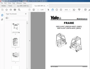
General 73
Frame Separation and Assembly 74
Disassemble 74
Assemble 74
Painting Instructions 75
Label Replacement 75
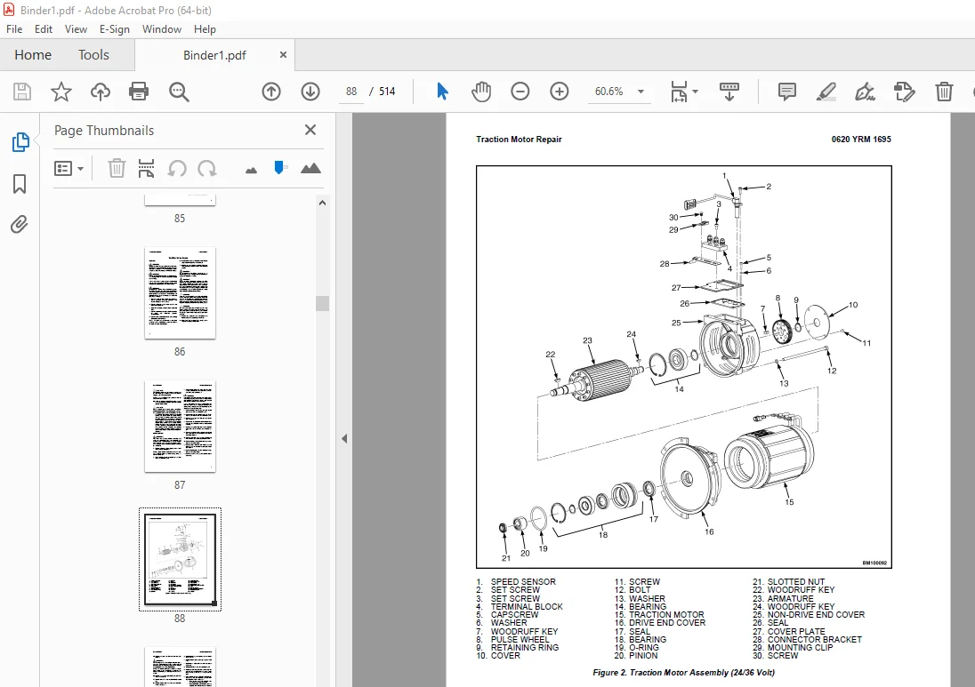
550101334-0620YRM1695-(06-2014)-US-EN 81
550101335-1600YRM1696-(05-2015)-US-EN 97
General 101
Discharging the Capacitors 102
Raising the Lift Truck 103
How to Raise the Drive Tire End 103
How to Raise the Entire Lift Truck 104
Description 104
Steering Handle Assembly 106
Steering Handle 106
Description 106
Remove 107
Disassemble 108
Assemble 111
Install 111
Steering Controller 112
Description 112
Remove 112
Install 112
Steering Proximity Switch 113
Replace 113
Steering Motor 114
Description 114
Remove 114
Disassemble 114
Assemble 115
Install 115
Troubleshooting 116
550101336-1800YRM1697-(03-2022)-US-EN 119
General 125
Accessing the Drive Unit Compartment 125
Description 127
Special Precautions 128
Repair 129
Air Gap 129
Brake Hub Alignment 130
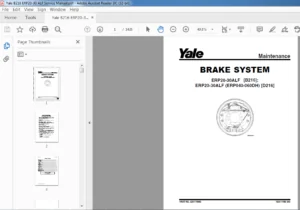
Remove 24V Brake Assembly 130
Remove 2-Stage Brake Assembly 132
Install 24V Brake Assembly 133
Install 2-Stage Brake Assembly 133
Troubleshooting 134
550101337-1900YRM1698-(06-2014)-US-EN 137
550101338-2200YRM1699-(09-2014)-US-EN 165
550101339-2200YRM1700-(04-2020)-US-EN 181
General 187
Introduction 187
Description 187
Button Keypad 187
LED Indicator Lights 187
LCD Screen 187
Dash Display Menu Access 187
Menu Navigation 188
Dash Display Menu Operation 188
Nodes 188
Menu Structure 188
Service-Level Menu 189
Hour Meters 190
H1 Truck Hours 191
H2 Traction Hours 191
H3 Pump Hours 191
H4 Steer Hours 191
H5 Odometer Hours 191
H10 Display Hours 191
H32 Combination Node Hours 191
H40 Steer Node Hours 191
Performance 192
Performance Level 1 192
P1 1 Forward 193
P1 2 Reverse 193
P1 3 Acceleration 193
P1 4 Plug 193
P1 5 Coast 193
P1 32 Steer Effort 193
P1 33 Steer Ratio 193
Operator Passwords 194
Add Password 194
Delete Password 194
Edit Password 194
Operator Password 194
Clear Log 195
Operator Logs 195
Operator 1-150 195
Information 195
I3 Serial Number 195
I5 Truck Voltage 195
Settings 196
S1 Metric 197
S2 User Performance 197
S3 Timeout 197
S4 Battery Type 197
S5 BDI Startup Full 197
S6 BDI Full 197
S7 BDI Empty 197
S8 BDI Reset 198
S9 Lift Interrupt 198
S10 Audible Warning 198
S11 Visual Warning 198
S12 Checklist 198
S13 Maint Reminder 198
S14 Restore Default 198
S15 Truck Lockout 199
S23 Set Steer 0 Positive 199
S25 Max CW Angle Fine 199
S27 Max CCW Angle Fine 199
S61 Extended Shift 199
Software Versions 199
Error Log 199
(E1) Error Log 1 200
Error 1 1 (E1 1) 200
Error 1 2 (E1 2) 200
Error 1 3 (E1 3) 200
Error 1 4 (E1 4) 200
Diagnostics 201
Diagnostics 201
D1 Status 201
D2 Input 201
D3 Output 201
D1 Status 201
D1 1 CAN 202
D1 2 Contactor 202
D1 3 Full Traction 202
D1 4 Limp Traction 202
D1 5 Steering 202
D1 6 Lift 202
D1 7 Lower 202
D2 Inputs 203
D2 10 Display 203
D2 10 1 Bus Error 203
D2 10 2 Bus Max Error 203
D2 10 32 Combination Controller 203
D2 10 40 Steer 203
D2 32 Combination Controller 204
D2 32 1 Target Speed 206
D2 32 2 Motor Speed 206
D2 32 3 Motor Encoder 206
D2 32 5 Controller Temperature 206
D2 32 6 Motor Temperature 206
D2 32 7 Motor Current 206
D2 32 8 Cap Voltage 206
D2 32 9 Cap Maximum Voltage 206
D2 32 10 Cap Minimum Voltage 206
D2 32 14 MC Connect 206
D 2 32 16 Horn Switch 206
D2 32 17 Brake Switch 206
D2 32 20 Pump Current 206
D2 32 28 Steer Status 206
D2 32 32 SOC 206
D2 32 33 Operator Sensor Switch 206
D2 32 34 Traction Input 206
D2 32 35 Lift/Lower Input 206
D2 32 36 Work Light Auto Switch 207
D2 32 37 Work Light Manual Switch 207
D2 32 38 Light Sensor 207
D2 40 Steer 207
D2 40 1 Target Speed 208
D2 40 2 Motor Speed 208
D2 40 3 Motor Encoder 209
D2 40 5 Controller Temperature 209
D2 40 7 Motor Temperature 209
D2 40 8 Cap Voltage 209
D2 40 9 Cap Maximum Voltage 209
D2 40 10 Cap Minimum Voltage 209
D2 40 11 Key Voltage 209
D2 40 12 Key Max Voltage 209
D2 40 13 Key Minimum Voltage 209
D2 40 17 Center Prox SW 209
D2 40 19 Steer Angle 209
D2 40 28 Pressure Sensor 209
D2 40 29 Steer Input A 209
D2 40 30 Steer Input B 209
D3 Output 210
D3 10 Display 210
D3 10 10 Display Com 210
D3 10 32 Combination Com 210
D3 10 40 Steer Com 210
D3 32 Combination Controller 211
D3 32 1 U-V Line DC Curr 212
D3 32 2 U-W Line DC Curr 212
D3 32 3 V-W Line DC Curr 212
D3 32 7 Pump Motor Short 212
D3 32 9 Load Hold 212
D3 32 10 Backup Alarm 212
D3 32 11 Strobe 212
D3 32 12 Horn 212
D3 40 Steer 212
D3 40 1 U-V Line DC Current 213
D3 40 2 U-W Line DC Current 213
D3 40 3 V-W Line DC Current 213
D3 40 4 Motor Open 213
D3 40 5 Motor Circuit 213
D3 40 6 Status Line 213
Calibration 213
550101340-2200YRM1701-(03-2022)-US-EN 217
General 225
Accessing the Drive Unit Compartment 226
Special Precautions 227
Discharging the Internal Capacitors 227
Major Electrical System Features 228
Integrated System 228
CANbus Advantages 228
CANbus Communications 228
Electric Steering 228
Centering Proximity Sensor 228
Traction 229
Combi 229
Input Devices 229
Output Devices 229
Encoder Integrity 229
Test Encoders 229
Proximity Switches 230
Key Switch 230
Multifunction Displays 230
BDI 230
Speed 230
Steer Angle 230
Truck Hours 230
Operational Mode 230
Setup 231
Setup Instructions 231
Combi Traction/Hydraulic Control Unit 231
Normal Operation 231
Display 231
Password Access 231
Startup Checklist 231
Truck Operation Mode 232
Diagnostics 232
Calibration 233
Traction Throttle 233
Lift/Lower 233
Contactor and Electrical Panel Checks 234
Contactors 234
General 234
Test 234
Tips 235
Disassemble and Assemble 235
Repairs 237
Controller, Replace 237
Remove 237
Install 239
Steering Controller, Replace 239
Remove 239
Install 241
HVC Controller, Replace 241
Remove 241
Install 241
Display 241
Contactor Coil, Check 242
Fuses 242
Key Switch 242
Replace 242
Power Disconnect Switch 244
Replace 244
Multifunction Controls 246
Multifunction Control Handle (Before February 2022) 246
Remove 246
Install 248
Multifunction Control Handle (After February 2022) 248
Multifunction Control Handle (After February 2022) 248
Inspection 249
Remove 249
Install 251
Multifunction Control Handle Adjustable Armrest (After February 2022) 251
Remove 252
Disassemble 252
Assemble 254
Install 254
Multifunction Control Handle Disassembly and Repair (After February 2022) 255
Handle Grip and Switch Repairs 255
Handle Grip Support Mounting 255
Handle Disassembly 256
Steering Handle 259
Steering Unit Repair 259
Foot Switches 263
Brake Switch 263
Operator Sensing (Before February 2022) 264
Repair 264
Operator Sensing System (After February 2022) 266
General 266
Remove 267
Install and Adjust 267
Dash Display Assembly 268
Description 268
Remove 268
Test 269
Install 269
Horn 270
Replace 270
Light Assemblies 270
Front Lights 270
Bulb Replacement (Before February 2022) 270
Assembly Replacement (Before February 2022) 271
Bulb and Assembly Replacement (After February 2022) 271
Ultrasonic Sensor Replacement (After February 2022) 272
Caution Light (Before February 2022) 273
Caution Light 273
Light Switches 273
Cooling Fans 275
Operator Fan 275
Repair 275
Proximity Switch (Steering) 276
Remove 276
Install 276
Troubleshooting 276
550101341-4000YRM1702-(02-2016)-US-EN 279
General 283
Description of Operation 283
Load Wheel 284
Remove 284
Install 284
Caster Adjustment 287
Casters 287
Caster Adjustment Check 287
Caster Adjust Procedure 288
Caster Repair 290
Caster Replacement 290
Disassemble 291
Assemble 291
Rear Link and Load Wheel 291
Remove 291
Install 293
Pull Rod 294
Remove 295
End Replacement 295
Install 295
Fork Height Adjustment 296
Rocker Arm 297
Remove 297
Install 298
Upper Link 299
Remove 299
Install 299
Entry Rollers 300
Replacement 300
Troubleshooting 301
550101342-8000YRM1703-(03-2022)-US-EN 305
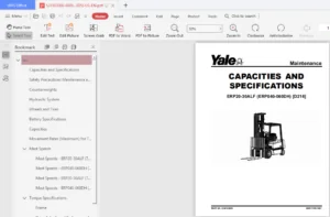
Hydraulic System 311
Hydraulic Oils 311
Gear Oils 311
Grease 312
Truck Weight 312
Tire Sizes 313
Torque Specifications 314
Drive Wheel Assembly 314
Master Drive Unit 314
Traction Motor 314
Steering System 314
Electrical 314
Lift Mechanism 314
Hydraulics 314
Battery Specifications 315
550101343-8000YRM1704-(03-2022)-US-EN 317
Schematic / Diagram 323
550101344-8000YRM1705-(03-2022)-US-EN 371
General 375
Operator’s Compartment Covers/Console 375
Operator’s Compartment Covers 375
Remove 375
Install 378
Operator’s Compartment Console 378
Remove 378
Install 380
Console Tray 381
Remove 381
Install 381
Drive Unit Compartment Door 381
Caster Wheel Cover 381
How to Move a Disabled Truck 382
How to Tow the Lift Truck 382
How to Put a Lift Truck on Blocks 383
How to Raise Drive/Steer Tire 383
How to Raise Load Wheels 383
Special Precautions 384
Discharging the Capacitors 384
Welding Repairs 384
Maintenance Schedule 385
Maintenance Procedures Every 8 Hours or Daily 390
Checks With Key Switch Turned OFF 390
Battery 390
Hydraulic Leaks 391
Drive Tire, Load Wheels, Casters, and Frame 391
Checks With Key Switch Turned ON 392
Operation 392
Maintenance Procedures Every 250 Hours or Every 6 Weeks 394
Caster Lubrication 394
Casters 394
Caster Adjustment Check 394
Caster Adjust Procedure 395
Maintenance Procedures Every 500 Hours or Every 3 Months 398
Hydraulic System 398
Hydraulic Oil 398
Hydraulic Reservoir Breather 398
Steering System 398
Power Steering 398
Lift Linkage and Load Wheels 399
Master Drive Unit 399
Change Gear Oil 399
Check Oil Level 399
Drive Tire Check 401
Maintenance Procedures Every 2000 Hours or Yearly 402
Lubrication 402
Repack Load Wheel Bearings 402
Hydraulic System 402
Oil Change 402
Brake 403
Electrical 403
Battery Maintenance 404
How to Charge the Battery 404
Equalizing Charge 404
Normal Charge 404
How to Change the Battery 405
Transporting 406
Loading 406
Unloading 406
Preparation for Storage 406
Short-Term Storage (1 to 6 months) 407
Long-Term Storage (6 months or longer) 407
Preparation for Use 407
Preparation After Shipment 407
Preparation After Storage 407
550101345-9000YRM1706-(03-2022)-US-EN 409
SECTION 9030 Electrical System 415
Group 03 – General Maintenance and Diagnostic Data 417
Group 20 – Diagnostic Trouble Codes 427
550267564-0630YRM2448-(09-2022)-US-EN 493
General 499
General 499
Description 499
Discharging The Capacitors 500
Master Drive Unit Repair 504
Maintenance 504
Draining the Oil 504
Remove 504
Disassemble 506
Clean and Inspect 507
Assemble 507
Install 508
Replace the Wheel Seal on Kordel Drive Units 508
Tools required 508
Truck setup 508
Wheel shaft seal and protection ring removal (method 1) 509
Wheel shaft seal and protection ring removal (method 2) 509
Wheel shaft seal and protection ring installation 511
Troubleshooting 512
S.V 05/24