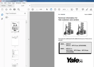
Yale Forklift C815 (NR035-045AE; NDR030AE) Service Manual – PDF DOWNLOAD
$30.95
Yale Forklift C815 (NR035-045AE; NDR030AE) Service Manual – PDF DOWNLOAD
Description
Yale Forklift C815 (NR035-045AE; NDR030AE) Service Manual – PDF DOWNLOAD
FILE DETAILS:
Yale Forklift C815 (NR035-045AE; NDR030AE) Service Manual – PDF DOWNLOAD
Language : English
Pages : 594
Downloadable : Yes
File Type : PDF
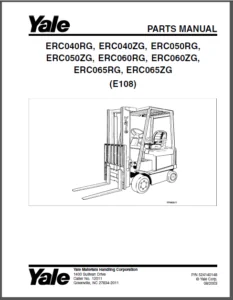
IMAGES PREVIEW OF THE MANUAL:
TABLE OF CONTENTS:
Yale Forklift C815 (NR035-045AE; NDR030AE) Service Manual – PDF DOWNLOAD
524150797-8000YRM0231-(02-2023)-US-EN 1
General 7
Threaded Fasteners 7
Nomenclature, Threads 7
Strength Identification 8
Cotter (Split) Pins 9
Fastener Torque Tables 14
Conversion Table 16
524150797-8000YRM0231-(03-2020)-US-EN 23
General 27
Threaded Fasteners 27
Nomenclature, Threads 27
Strength Identification 28
Cotter (Split) Pins 29
Fastener Torque Tables 34
Conversion Table 36
524158040-2240YRM0001-(01-2023)-US-EN 43
General 49
Battery Type 49
Lead-Acid Batteries 49
Lithium-Ion Batteries 50
Specific Gravity 50
Chemical Reaction in a Cell 50
Electrical Terms 52
Battery Selection 53
Battery Voltage 54
Battery as a Counterweight 54
Battery Ratings 54
Kilowatt-Hours 54
Battery Maintenance 55
Safety Procedures 55
Maintenance Records 55
New Battery 55
Cleaning Battery 56
Adding Water to Battery 58
Hydrometer 58
Battery Temperature 59
Charging Battery 60
Types of Battery Charges 61
Methods of Charging 62
Troubleshooting Charger 63
Knowing When Battery Is Fully Charged 63
Where to Charge Batteries 63
Equipment Needed 63
Battery Connectors 64
Battery Care 64
Troubleshooting 66
524158040-2240YRM0001-(03-2020)-US-EN 71
General 75
Battery Type 75
Lead-Acid Batteries 75
Lithium-Ion Batteries 76
Specific Gravity 76
Chemical Reaction in a Cell 76
Electrical Terms 78
Battery Selection 78
Battery Voltage 79
Battery as a Counterweight 80
Battery Ratings 80
Kilowatt-Hours 80
Battery Maintenance 80
Safety Procedures 80
Maintenance Records 81
New Battery 81
Cleaning Battery 81
Adding Water to Battery 83
Hydrometer 84
Battery Temperature 85
Charging Battery 86
Types of Battery Charges 86
Methods of Charging 88
Troubleshooting Charger 88
Knowing When Battery Is Fully Charged 89
Where to Charge Batteries 89
Equipment Needed 89
Battery Connectors 90
Battery Care 90
Troubleshooting 92
524164462-0100YRM0975-(07-2002)-US-EN 97
toc 97
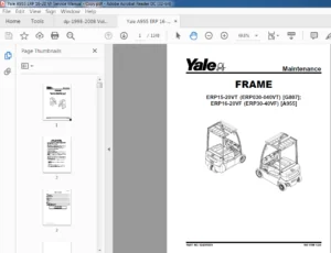
Frame 97
Safety Precautions Maintenance and Repair 98
General 101
Description 101
Repairs – General 101
Covers, Panels, and Plates 101
Replace Load Wheels 103
Overhead Guard Repair 106
Changes to Overhead Guard 107
Remove 107
Install 107
Painting Instructions 107
Safety Labels Replacement 108
tables 97
Table 1 Unit and Model Numbers 101
524164464-1600YRM0974-(07-2002)-US-EN 113
toc 113
Steering System 113
Safety Precautions Maintenance and Repair 114
General 117
Description 117
Steering Control Unit Assembly 118
Description 118
Remove 118
Steering Control Unit 118
Description 118
Operation 118
Remove 119
Repair 119
Disassemble (Before May 2002) 119
Disassemble (After May 2002) 120
Clean 122
Reassemble (Before May 2002) 123
Reassemble (After May 2002) 123
Install 124
Steering Pump and Motor Assembly 124
Description 124
Pump and Motor 124
Remove and Disassemble 124
Assemble and Install 125
Pump 125
Remove 125
Install 126
Disassemble 126
Assemble 127
Axle Assembly Repair 128
General 128
Traction Motor 128
Description 128
Remove 128
Install 128
Master Drive Unit 129
Description 129
Remove Chain-Steered MDU 129
Install 129
Hydraulic Steering Motor 130
Description 130
Remove 130
Install 131
Caster Wheels 132
Description 132
Caster Replacement 132
Wheel Replacement 133
Axle Weldment 133
Remove 133
Install 133
Check and Adjust 134
Remove Air From Steering System 134
Check Steering Chain 134
Check Articulation Stop Adjustment 134
Steering Pressure 136
Troubleshooting 138
tables 113
Table 1 Articulation Adjustment Chart 135
524164465-1800YRM0976-(07-2002)-US-EN 143
toc 143
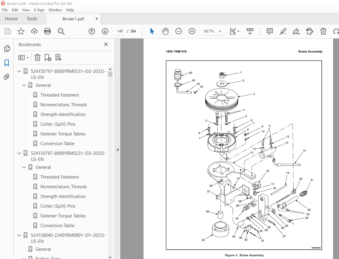
Brake System 143
Safety Precautions Maintenance and Repair 144
General 147
Brake Assembly 147
Remove and Disassemble 147
Assemble and Install 150
Master Cylinder and Pedal Assembly 151
Remove and Disassemble 151
Assemble and Install 151
Floor Plate Assembly 153
Remove and Disassemble 153
Assemble and Install 153
Master Cylinder 153
Disassemble 153
Assemble 153
Slave Cylinder 155
Disassemble 155
Assemble 155
Brake Switch Replacement 156
Brake Adjustment 157
Brake System Air Removal 157
Troubleshooting 157
524164467-1900YRM0973-(12-2004)-US-EN 161
toc 161
Hydraulic System 161
Safety Precautions Maintenance and Repair 162
General 165
Description 165
Control Handle 166
Description 166
Control Valve 167
Description 167
Trucks Built Before 15 July, 2002 167
Trucks Built After 15 July, 2002 167
Control Valve-Manual Lowering 167
Trucks Built Before 15 July, 2002 167
Trucks Built After 15 July, 2002 168
Remove 168
Install 168
Check and Adjust 169
Main Relief Valve (NDR030AE, NR035/040/045AE, NS040/050AF, NDR03 169
Main Relief Valve (NDR030GB, NR045GB) 169
Auxiliary Relief Valve 170
Lift Pump and Motor 171
Description 171
Remove 171
Install 173
Disassemble 173
Assemble 174
Steering Pump 174
Hydraulic Tank 174
Description 174
Remove and Disassemble 174
Assemble and Install 175
Troubleshooting 176
tables 161
Table 1 Hydraulic Tank Capacities 174
524164468-2200YRM0977-(08-2005)-US-EN 185
toc 185
SEM Traction Motor Controller 185
Safety Precautions Maintenance and Repair 186
SEM Traction Motor Controller 189
Description/Features 189
Remove 189
Test 190
Install 190
1307 Programmer Handset 191
Description/Features 191
SCROLL DISPLAY Keys 192
CHANGE VALUE Keys 192
MORE INFO Key 192
Operation 192
Connecting Handset to Traction Motor Controller 192
Disconnecting Handset From Traction Motor Controller 193
Programmer Self Test 193
Operating Modes 193
Program Menu 193
Test Menu 194
Diagnostics Menu 195
Diagnostic History 195
Special Program Menu 195
Programming the Traction Motor Controller – 1307 Handset 196
1311 Programmer Handset 199
Description/Features 199
Menu Navigation Key 199
Data Increase/Decrease Key 200
Bookmark Keys 200
Operation 200
Connecting Handset to Traction Motor Controller 200
Disconnecting the Handset From the Traction Motor Controller 200
Main Menu Selections 201
Program Menu 201
Monitor Menu 201
Faults Menu 202
Functions menu 202
Information Menu 203
Programmer Setup Menu 203
Programming the Traction Motor Controller – 1311 Handset 203
Troubleshooting 204
Status LED Diagnostics 204
Diagnostics Menu 205
Test Menu 215
tables 185
Table 1 Program Menu 194
Table 2 Test Menu 194
Table 3 Dash Display Drive Mode Inputs 195
Table 4 Diagnostics and Diagnostic History Display 195
Table 5 Special Program Menu 196
Table 6 Program Menu Range and Default Values 197
Table 7 Status LED Fault Codes 205
524164469-2200YRM0978-(05-2005)-US-EN 221
toc 221
Electrical System 221
Safety Precautions Maintenance and Repair 222
General 227
Component Repair and Testing – General 228
Contactor Panel Assembly 228
Description/Features 228
Remove 228
Install 229
Contactors 229
Description/Features 229
Auxiliary Switch 230
Testing 230
Remove 231
Install 231
EE Contactors 231
Fuses 233
Relays 234
Description/Features 234
Enable Relay 234
Hourmeter Relay 234
Lift/Lower Relay (Trucks Built After 1 August 2002) 234
Coil Testing 234
Contact Testing 235
Remove and Install 235
Height Proximity Switch 236
Remove 236
Test 236
Install 237
Adjust 237
Key Switch 237
Description 237
Remove 237
Install 237
Battery Disconnect Switch 238
Description 238
Remove 238
Install 238
Proportional Electro-Hydraulic Control Valves 239
Manual Lowering 239
Trucks Built Before 1 August, 2002 239
Trucks Built After 1 August, 2002 240
Operation 240
Repair 240
Carriage Valve Assembly and Selector Valves 240
Test/Remove/Install 241
Multifunction Control Handle 241
Description/Features 241
Remove 242
Disassemble 243
Tools Required 243
Assemble 245
Install 245
Shelf Height Selector 246
Description/Features 246
Shelf Height Selector 246
Power On, Start Up 246
Programming 246
Field Program Mode 246
Enter Shelf Level 246
Set Shelf Level 247
Quick Pick Level Keys 247
Set Minimum Lift Speed 247
Set Minimum Lower Speed 247
Changing the 3-Digit Security Code 247
Factory Program Mode 248
Calibrate Lift 248
Set Options 248
Control Zone 249
Deadband 249
Reset User Code 249
Clear All 249
Show All Levels 249
Set LCD Bias 249
Show Analog 249
External Inputs 249
System Errors 250
Main Interface Board (MIB) Adjustments 250
Function 32 Hydraulic Potentiometer – Set-Up 250
Function 02 Lift Minimum Rate 250
Function 04 Lower Minimum Rate 250
Function 59 Hydraulic Lift Function – Stopping Rate 250
Function 61 Hydraulic Lower Function – Stopping Rate 251
Main Interface Board (MIB) 251
Description/Features 251
Operation 251
LED Display 252
MIB, Remove 252
MIB J-Connector, Repair 253
Inspect 253
MIB, Install 254
Main Interface Board (MIB) Setup Procedures 255
General 255
Default Values 255
Checking Model Code, Software Version, and Setup Status 255
MIB Generation II Setup Procedure 255
Entering the Setup Mode 255
Editing Settings 255
Changing the Setting Values 256
Entering Text 256
System Information and Fault Log 256
Passwords 256
Defaults 256
Exit and Save 256
Parameters 257
Top Level Menu Items 257
Options 257
Handle Deadband 257
Lift/Lower 257
Speeds 258
Auxiliary 258
Max Speed and Low End Adjustments 259
Customizing MIB Functions 259
MIB Status, Warning, and Fault Codes 272
General 272
Troubleshooting Charts 273
Blank or Undefined Code Conditions 274
Status Codes 278
Warning Codes 282
Fault Codes 286
SEM Traction Motor Controller 295
Description/Features 295
Remove 295
Test 296
Install 296
1307 Programmer Handset 298
Description/Features 298
SCROLL DISPLAY Keys 298
CHANGE VALUE Keys 298
MORE INFO Key 298
Operation 299
Connecting Handset to Traction Motor Controller 299
Disconnecting Handset from Traction Motor Controller 299
Programmer Self Test 299
Operating Modes 300
Program Menu 300
Test Menu 301
Diagnostics Menu 301
Diagnostic History 302
Special Program Menu 302
Programming the Traction Motor Controller – 1307 Handset 303
1311 Programmer Handset 305
Description/Features 305
Menu Navigation Key 306
Data Increase/Decrease Key 306
Bookmark Keys 306
Operation 306
Connecting Handset to Traction Motor Controller 306
Disconnecting the Handset From the Traction Motor Controller 307
Main Menu Selections 307
Program Menu 307
Monitor Menu 308
Faults Menu 308
Functions menu 309
Information Menu 309
Programmer Setup Menu 310
Programming the Traction Motor Controller – 1311 Handset 310
Troubleshooting 311
Status LED Diagnostics 311
Programmer Diagnostics 312
Diagnostics Menu 313
Test Menu 322
Dash Display Assembly 325
Description and Features 325
Operation 326
Battery Indicator 326
Remove 327
Install 327
Voltage Selection 328
Dash Display, Adjust 328
Battery Indicator Profile Settings 329
Troubleshooting 329
Inoperative Dash Display Assembly 329
Inoperative Drive Mode Selection 329
Troubleshooting the Dash Display With a Programmer Handset 330
Troubleshooting Without a Programmer Handset 330
No Warnings or Faults Displayed 330
Lift Interrupt 331
Lost MIB Signal Displayed 331
Hourmeter Input 331
tables 221
Table 1 Contactor Coil Voltages 230
Table 2 Fuses 234
Table 3 Hydraulic Control Valve/Relay Coil Resistance Values 235
Table 4 OPTS Bits 248
Table 5 Truck Unit and Model Codes 255
Table 6 MIB Function Code Values for NR035AE Software 06/01/01 259
Table 7 MIB Function Code Values for NR040AE 06/01/01 to 01/14/ 260
Table 8 MIB Function Code Values for NDR030AE 261
Table 9 MIB Function Code Values for NS050AF 262
Table 10 MIB Function Code Values for NR045CB 262
Table 11 MIB Function Code Values for NDR030CB 263
Table 12 MIB Function Code Values for NR045GB Mast Full Height 264
Table 13 MIB Function Code Values for NR045GB Mast Full Height 264
Table 14 MIB Function Code Values for NDR030GB Mast Full Height 265
Table 15 MIB Function Code Values for NDR030GB Mast Full Height 265
Table 16 MIB Software 01/14/02 to 03/27/02 NR/NDR AE, NSAF (C81 266
Table 17 MIB Software 01/14/02 to 03/27/02 NR/NDRCB and GB (D82 267
Table 18 MIB Software Post 03/27/02 NR/NDRAE C815 268
Table 19 MIB Software Post 03/27/02 NR/NDRCA (D829) and NR/NDRC 270
Table 20 NR/NDRGA (B861) 271
Table 21 Program Menu 300
Table 22 Test Menu 301
Table 23 Dash Display Drive Mode Inputs 301
Table 24 Diagnostic and Diagnostic History Display 301
Table 25 Special Program Menu 302
Table 26 Program Menu Range and Default Values 304
Table 27 Status LED Fault Codes 311
Table 28 Dash Display Drive Mode Inputs 330
Table 29 Dash Display Drive Mode Test Voltages 330
Table 30 Dash Display Status/Warning/Fault Test Voltages 331
524164470-4000YRM0480-(08-2016)-US-EN 335
General 339
Mast Weldments 341
Carriages 342
Two-Stage Mast 344
Description 345
Operation 350
Three-Stage Mast 351
Description 351
Operation 354
524164471-4000YRM0482-(05-2018)-US-EN 359
General 363
Safety Procedures When Working Near Mast 363
Load Backrest Extension, Carriage, Load Rollers, Side Rollers, and Forks 364
Load Backrest Extension, Remove and Install 365
Carriage Assembly, Remove and Install 365
Carriage Load Rollers, Remove and Install 368
Side Rollers, Disassemble and Assemble 368
Fork, Replace 369
Hook-Type Forks 369
Remove 369
Install 369
Forks Check 369
Two-Stage Mast Assembly 372
Remove 372
Clean and Inspect 377
Lift Cylinders, Remove and Install Dual-Lift Cylinders 378
Lift Cylinder, Remove and Install Single Main-Lift Cylinders 379
Remove 379
Install 380
Inner Mast Assembly, Remove and Install 381
Hoses, Replace 381
Hose and Cable Sheaves, Replace 381
Two-Stage Lift Chains 383
Remove and Install 383
Clean and Inspect 383
Two-Stage Chain Sheave, Remove and Install 384
Load Rollers and Wear Plugs, Remove and Install 384
Two-Stage Mast Assembly, Install 385
Three-Stage Mast Assembly 386
Three-Stage Mast Assembly, Remove 386
Clean and Inspect 387
Free-Lift Cylinder, Remove and Install 390
Main Cylinders (Standard), Remove and Install 391
Inner and Intermediate Mast Assemblies, Remove and Install 393
Hoses, Replace 393
Hose and Cable Sheaves, Replace 395
Free-Lift Hose Sheave 395
Carriage Sheaves 395
Three-Stage Lift Chains, Remove and Install 396
General 396
Free-Lift Chains 396
Main-Lift Chains 396
Three-Stage Chain Sheaves, Disassemble and Assemble 397
Free-Lift Chain Sheaves 397
Main-Lift Chain Sheaves 397
Load Rollers and Wear Plugs, Remove and Install 397
Three-Stage Mast Assemble, Install 398
Mast Operation Check 399
Hydraulic System Leaks Check 399
Lift Chains Check 400
General 400
Clean and Inspect 400
Lubrication 401
Mast Adjustments 401
General 402
Adjust Wear Plugs – Mast 402
Adjust Free-Lift Chain (Three-Stage Only) 404
Adjust Main-Lift Chains 404
Two-Stage 404
Three-Stage 406
Adjust Wear Strips 406
Carriage Adjustments 407
Adjust Wear Plug – Carriage 407
Adjust Side Rollers – Carriage 407
Adjust Thrust Rollers – Carriage 408
Troubleshooting 409
524164473-4000YRM0481-(08-2016)-US-EN 413
General 417
Description 417
Lowering Control Valve 418
Main Cylinder Repair 419
Disassemble 420
Assemble 421
Free-Lift Cylinder Repair 422
Disassemble 422
Assemble 422
Troubleshooting 424
524164474-4500YRM0971-(05-2018)-US-EN 427
General 431
Safety Procedures When Working Near Mast 431
Description 433
Reach Assemblies 433
Repair – General 435
Load Backrest Removal and Installation 435
Fork Replacement 436
Hook Forks 436
General 436
Remove 436
Install 437
Forks Check 437
Reach Assembly Removal and Installation 439
Carriage Load Rollers Removal and Installation 439
Side Rollers Disassembly and Assembly 441
Reach Assembly Repair 441
Reach Assembly Outer Frame 441
Remove 441
Disassemble 444
Clean and Inspect 445
Assemble 445
Install 445
Remove Without Sideshifter 445
Disassemble Without Sideshifter 446
Clean and Inspect 446
Assemble Without Sideshifter 447
Install Without Sideshifter 447
Single-Reach Scissor Arms 448
Remove and Disassemble 448
Clean and Inspect 451
Assemble and Install 451
Double-Reach Scissor Arms 452
Remove and Disassemble 452
Clean and Inspect 456
Assemble and Install 456
Frame AssemblyInner 457
Remove 459
Disassemble 460
Clean and Inspect 461
Assemble 461
Install 462
Reach Cylinders 463
Remove 463
Disassemble 464
Clean and Inspect 464
Assemble 465
Install 465
Tilt Cylinder 465
Remove 465
Clean, Inspect, and Repair 466
Install 467
Sideshift Cylinder 468
Remove 468
Clean and Inspect 468
Reach/Tilt Selector Valve 468
Remove 468
Disassemble 468
Clean and Inspect 469
Assemble 469
Install 469
Reach Assembly AdjustmentsCarriage or 469
Adjust Wear Plug 469
Adjust Side Rollers 471
Adjust Thrust Rollers 472
Adjust Reach Cylinders 472
Specifications 473
Troubleshooting 476
(NDR030GB, NR045GB, NDR030AE,NR035/040/045AE, NDR030CB, NR045CB and NS040/050AF) 476
(MRW020/030-E) 477
524164475-8000YRM0970-(09-2013)-US-EN 481
toc 481
Periodic Maintenance 481
Safety Precautions Maintenance and Repair 482
General 485
Discharging the Capacitors 485
How to Move Disabled Truck 486
How to Tow Lift Truck 486
How to Put Lift Truck on Blocks 487
How to Raise Load Wheels 487
How to Raise Steer Wheel 487
How to Raise the Entire Lift Truck 487
Safety Procedures When Working Near Mast 488
Maintenance Schedule 489
Maintenance Procedures Every 8 Hours or Daily 495
Checks With Key Switch Turned OFF 495
Battery 495
Hydraulic System 496
Tires and Wheels 498
Safety Labels 498
Overhead Guard 498
Mast, Forks, and Lift Chains 499
Reach, Tilt, and Sideshift 501
Forks 501
Remove 501
Install 502
Lift Chain Adjustments 502
Checks With Key Switch Turned ON 504
Operation 504
Instruments and Controls 504
Lift System Operation 507
Multifunction Control Handle 507
Brake 508
C815, C816, and D829 508
B861 508
Steering System 509
Maintenance Procedures Every 350 Hours or 2 Months 509
Master Drive Unit 509
Brake 509
C815, C816, and D829 509
B861 509
Hydraulic System 510
Articulation Stop Adjustment 510
Adjustment Procedure 511
Lift System Operation 511
Forks 511
Mast 511
Lift Chains 511
Other Lubrication 513
Electrical Inspection 513
Fuses 513
Contactors 514
Motor Brushes 514
Maintenance Procedures Every 2000 Hours or Yearly 516
Hydraulic System 516
Change Hydraulic Oil 516
Change Hydraulic Oil Filter 516
Check Hydraulic Oil Strainer 516
Brakes 516
Maintenance Procedures Every 3000 Hours or Three Years 517
Traction Motor 517
Lift and Tilt System Leaks Check 517
Lift System 517
Tilt System 518
Brakes Adjustment 518
C815, C816, and D829 518
B861 518
Battery Maintenance 520
How to Charge Battery 520
How to Change Battery 521
Tires and Wheels 524
Drive Tire 524
How to Change Drive Tire 524
Tandem Load Wheels 525
Single Load Wheel 525
Caster Wheels 526
C815, C816, and D829 526
B861 527
Preparation for Storage 528
Short-Term Storage (1 to 6 months) 528
Long-Term Storage (6 months or longer) 528
Transporting 529
Loading 529
Unloading 530
Preparation for Use 531
Preparation After Shipment 531
Preparation After Storage 531
tables 481
Table 1 Maintenance Schedule 492
Table 2 Articulation Adjustment Chart 510
Table 3 Fuses 513
Table 4 Hydraulic Tank Capacities 516
Table 5 Battery Size Specifications 523
Table 6 Tires and Wheels 524
524164476-8000YRM0972-(10-2007)-US-EN 535
toc 535
Capacities and Specifications 535
Safety Precautions Maintenance and Repair 536
SEM Traction Motor Controllers Factory Values and Min/Max Ranges 539
Lift Capacities 540
Articulation Adjustment 541
Master Drive Unit Specifications 541
Oil Capacities 541
Lubrication Specifications 542
Hydraulic Systems Specifications 542
Reach Carriage Specifications 543
Battery Size Specifications 544
Tire Sizes 545
Fuses 545
Steering Pump Specifications 545
Hydraulic Control Valve/Relay Coil Resistance Values 546
524164477-8000YRM0980-(11-2004)-US-EN 549
toc 549
Diagrams 549
Safety Precautions Maintenance and Repair 550
524166250-0630YRM1022-(08-2009)-US-EN 567
toc 567
Master Drive Unit 567
Safety Precautions Maintenance and Repair 568
HFK400 Master Drive Unit 571
General 571
Description 571
Drive Unit Maintenance and Repair 572
Remove 572
Install 573
Disassemble 573
Assemble 577
Troubleshooting 585
GK Master Drive Unit 587
General 587
Description 587
Maintenance 588
Changing the Oil 588
Traction Motor and Drive Unit Splines 588
Remove 588
Assemble 589
Mounting Electric Motor 590
Pivoted Connection – Geared Steering 590
Disassemble 591
Install 591
Troubleshooting 592
tables 567
Table 1 Tooth Contact Pattern 582
S.V 05/24