Yale Forklift C896 (MPE060-F) Service Manual – PDF DOWNLOAD
$30.95
Yale Forklift C896 (MPE060-F) Service Manual – PDF DOWNLOAD
Description
Yale Forklift C896 (MPE060-F) Service Manual – PDF DOWNLOAD
FILE DETAILS:
Yale Forklift C896 (MPE060-F) Service Manual – PDF DOWNLOAD
Language : English
Pages : 590
Downloadable : Yes
File Type : PDF
IMAGES PREVIEW OF THE MANUAL:
TABLE OF CONTENTS:
Yale Forklift C896 (MPE060-F) Service Manual – PDF DOWNLOAD
524150797-8000YRM0231-(02-2023)-US-EN 1
General 7
Threaded Fasteners 7
Nomenclature, Threads 7
Strength Identification 8
Cotter (Split) Pins 9
Fastener Torque Tables 14
Conversion Table 16
524150797-8000YRM0231-(03-2020)-US-EN 23
General 27
Threaded Fasteners 27
Nomenclature, Threads 27
Strength Identification 28
Cotter (Split) Pins 29
Fastener Torque Tables 34
Conversion Table 36
524158040-2240YRM0001-(01-2023)-US-EN 43
General 49
Battery Type 49
Lead-Acid Batteries 49
Lithium-Ion Batteries 50
Specific Gravity 50
Chemical Reaction in a Cell 50
Electrical Terms 52
Battery Selection 53
Battery Voltage 54
Battery as a Counterweight 54
Battery Ratings 54
Kilowatt-Hours 54
Battery Maintenance 55
Safety Procedures 55
Maintenance Records 55
New Battery 55
Cleaning Battery 56
Adding Water to Battery 58
Hydrometer 58
Battery Temperature 59
Charging Battery 60
Types of Battery Charges 61
Methods of Charging 62
Troubleshooting Charger 63
Knowing When Battery Is Fully Charged 63
Where to Charge Batteries 63
Equipment Needed 63
Battery Connectors 64
Battery Care 64
Troubleshooting 66
524158040-2240YRM0001-(03-2020)-US-EN 71
General 75
Battery Type 75
Lead-Acid Batteries 75
Lithium-Ion Batteries 76
Specific Gravity 76
Chemical Reaction in a Cell 76
Electrical Terms 78
Battery Selection 78
Battery Voltage 79
Battery as a Counterweight 80
Battery Ratings 80
Kilowatt-Hours 80
Battery Maintenance 80
Safety Procedures 80
Maintenance Records 81
New Battery 81
Cleaning Battery 81
Adding Water to Battery 83
Hydrometer 84
Battery Temperature 85
Charging Battery 86
Types of Battery Charges 86
Methods of Charging 88
Troubleshooting Charger 88
Knowing When Battery Is Fully Charged 89
Where to Charge Batteries 89
Equipment Needed 89
Battery Connectors 90
Battery Care 90
Troubleshooting 92
524164715-0630YRM0961-(03-2022)-US-EN 97
General 105
Check Oil Level 106
Change Gear Oil MTR005-007-F, MPE060-080-F, MPC060-080-F, MPE060-VG, MPE080-VG, MPE060VH, and MPE080VH 107
Drive Tire 107
Remove 107
Install 107
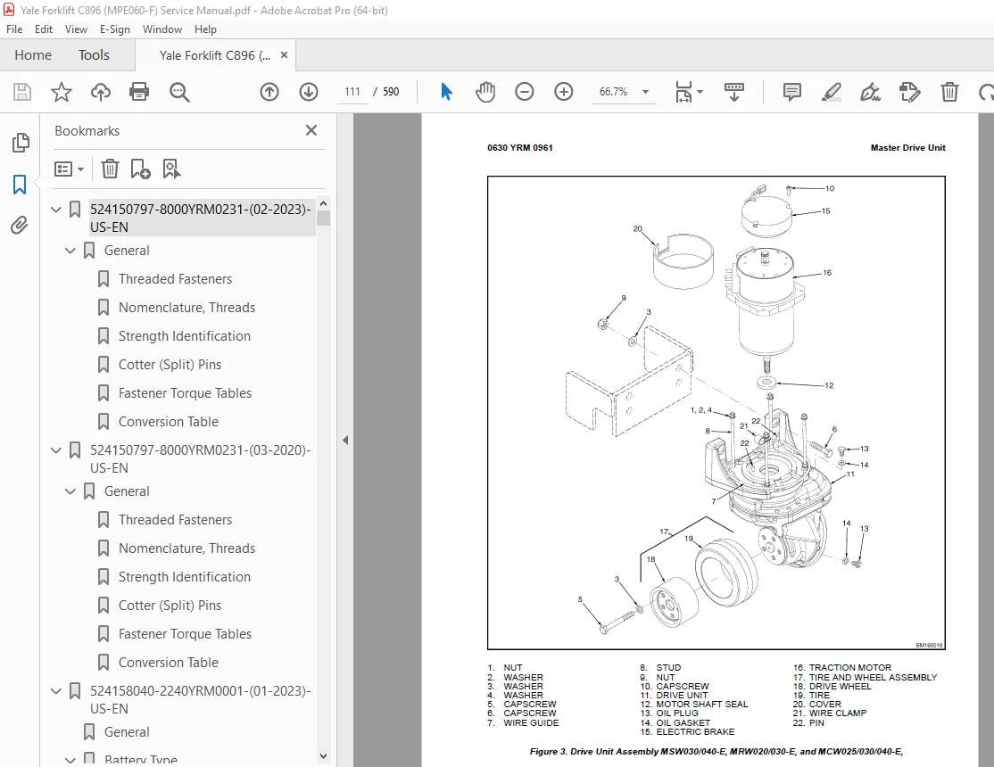
Master Drive Unit 108
Remove 108
Disassemble 115
Remove Drive Axle Group 115
Remove Upper Housing Group 116
Remove Pinion Group 116
Install 118
Troubleshooting 120
524164715-0630YRM0961-(12-2018)-US-EN 123
General 131
Check Oil Level 132
Change Gear Oil MTR005-007-F, MPE060-080-F, MPC060-080-F, MPE060-VG, MPE080-VG, MPE060VH, and MPE080VH 133
Drive Tire 133
Remove 133
Install 133
Master Drive Unit 133
Remove 133
Disassemble 140
Remove Drive Axle Group 140
Remove Upper Housing Group 140
Remove Pinion Group 140
Install 143
Troubleshooting 145
524274699-0620YRM1283-(12-2018)-US-EN 149
General 153
Accessing the Drive Unit Compartment 153
MPE060VG and MPE080VGMPE060VH and MPE080VH 153
MPC060/080-F and MTR005/007-F 154
Special Precautions 156
Discharging the Capacitors 156
Description 158
AC Motor Repair 158
Remove 158
Disassemble 159
Inspect 161
Assemble 161
Install 161
Troubleshooting 162
550090075-8000YRM1643-(03-2018)-US-EN 167
550090078-8000YRM1644-(01-2016)-US-EN 195
General 199
How to Move a Disabled Truck 199
How to Tow the Lift Truck 200
How to Put a Lift Truck on Blocks 201
How to Raise Drive/Steer Tire 201
How to Raise Load Wheels 203
Accessing the Drive Unit Compartment 203
Special Precautions 205
Discharging the Capacitors 205
Welding Repairs 206
Maintenance Schedule 206
Maintenance Procedures Every 8 Hours or Daily 210
Checks With Key Switch Turned OFF 210
Battery 210
Hydraulic Leaks 211
Drive Tire, Load Wheels, Casters, and Frame 211
Checks With Key Switch Turned ON 212
Operation 212
Maintenance Procedures Every 250 Hours or Every 6 Weeks 214
Caster Lubrication 214
Caster Lubrication (MPE060-F and MPE060-VG) 215
Maintenance Procedures Every 500 Hours or Every 3 Months 216
Hydraulic System 216
Hydraulic Oil 217
Hydraulic Reservoir Breather 217
Steering System 217
Power Assist Steering 217
Lift Linkage and Load Wheels 218
Casters 218
Caster Adjustment Check 218
Caster Adjust Heavy-Duty 218
Casters (MPE060-F and MPE060-VG) 219
Caster Shim Check 219
Caster Shim Adjust 220
Master Drive Unit 221
Change Gear Oil 221
Check Oil Level 221
Kordel MDU 222
Drive Tire Check 222
Maintenance Procedures Every 2000 Hours or Yearly 222
Lubrication 222
Repack Load Wheel Bearings 222
Repack Steer Bearings (Manual Steer Only) 222
Hydraulic System 223
Oil Change 223
Brake 223
Electrical 224
MDU 224
Oil Change (Carraro) 224
Oil Change (Kordel) 224
Battery Maintenance 225
How to Charge the Battery 225
Equalizing Charge 226
Normal Charge 226
How to Change the Battery 226
Changing Battery With Rollers 228
Remove 228
Install 228
Transporting 228
Loading 229
Unloading 229
Preparation for Storage 230
Short-Term Storage (1 to 6 months) 230
Long-Term Storage (6 months or longer) 230
Preparation for Use 230
Preparation After Shipment 230
Preparation After Storage 230
550091255-0100YRM1636-(02-2017)-US-EN 233
General 237
Frame Separation and Assembly 237
Disassemble 238
Assemble 238
Painting Instructions 239
Label Replacement 239
550091256-1600YRM1637-(02-2017)-US-EN 243
General 247
Accessing the Drive Unit Compartment 247
Special Precautions 248
Electromagnetic Shield 248
Calibration 249
Power Assist Steering 249
Control Handle 250
Control Handle Head 250
Control Handle 250
Standard Steering 250
Remove 251
Install 251
Power Assist Steering 253
Remove 253
Install 254
Gas Spring 255
Discharging the Gas Spring 255
Remove 255
Install 256
Articulating Shaft and Pinions (EPAS) 256
Remove 257
Pinion Repair 258
Upper Pinion 258
Lower Pinion 259
Install 260
Steer Motor Assembly 260
Repair 260
Steer Motor, Replace 261
Steer Motor Gear, Replace 262
Gearbox/Complete Assembly, Replace 262
Steer Support Assembly 263
Standard Steering 263
Remove (Complete Unit) 263
Disassemble 263
Assemble 265
Install (Complete Unit) 265
Power Assist Steering (Option) 266
Remove (Complete Unit) 266
Disassemble 266
Support Base 266
Steer Swivel 268
Assemble 268
Steer Swivel 268
Support Base 269
Install (Complete Unit) 270
Smart Coast Control (Option) 271
Disassemble 271
Assemble 273
Coast Control Adjustment Procedure 274
Troubleshooting 276
550091257-1800YRM1638-(10-2019)-US-EN 279
General 283
Accessing the Drive Unit Compartment 283
Description 284
Special Precautions 285
Brake Check 286
Brake Release 286
Brake Apply 287
Air Gap 287
Hold On Grade Test 289
Brake Assembly Repair 289
MPE060-F, MPE060-G, MPE060-VG and MPE060VH 289
Remove 289
Repair 291
Install 291
MPE080-VG and MPE080VH 291
Remove 291
Repair 293
Install 293
Troubleshooting 294
550091258-1900YRM1639-(12-2018)-US-EN 297
General 301
Description of Operation 301
Lifting a Load 302
Lowering a Load 306
Hydraulic Lines 306
Hydraulic Oil 306
Clean 306
Sound Level 306
Special Precautions 306
Hydraulic Reservoir 307
Drive Unit Compartment Covers 307
Lift Pump and Motor 309
General 309
Remove 309
Lift Pump and Motor Assembly 309
Disassemble 310
Remove Reservoir 310
Remove Pump Motor 312
Disassemble Pump 312
Assemble 312
Assemble Pump 312
Install Pump Motor 312
Install Reservoir to Pump 313
Install 313
Lift Pump and Motor Assembly 313
Valve Repair 314
Lowering Valve 314
Remove 314
Install 314
Relief Valve 315
Remove 315
Install 315
Check Valve 315
Remove 315
Install 316
Lift Cylinder 316
Remove 316
Disassemble 318
Assemble 318
Install 319
Relief Valve Pressure Check 319
Relief Valve Adjust 321
Troubleshooting 321
Lift Assemblies 321
Lift Cylinders 322
Lift Pump and Motor Assembly 323
550091259-2200YRM1658-(02-2017)-US-EN 327
General 331
Introduction 331
Description 331
Button Keypad 331
LED Indicator Lights 331
LCD Screen 331
Dash Display Menu Access 332
Menu Navigation 332
Dash Display Menu Operation 332
Nodes 332
Menu Structure 333
Supervisor-Level Menu 333
Hour Meters 334
H1 Truck Hours 334
H2 Traction Hours 334
H3 Pump Hours 334
H4 Steer Hours 334
H5 Odometer Hours 335
H10 Display Hours 335
H32 Combination Node Hours 335
H40 Steer Node Hours 335
Performance 335
Performance Level 1 336
P1 1 Forward 337
P1 2 Reverse 337
P1 3 Acceleration 337
P1 4 Plug 337
P1 5 Coast 337
P1 6 Lift Speed 337
P1 7 Lower Speed 337
P1 26 Pick Speed 337
P1 27 Pick Accel 337
P1 28 Pick Decel 338
P1 29 MIN Steer Assist F 338
P1 30 MIN Steer Assist R 338
P1 31 Max Steer Assist 338
Operator Passwords 338
Add Password 339
Delete Password 339
Edit Password 339
Operator Password 339
Clear Log 339
Operator Logs 340
Operator 1-150 340
Information 341
I1 Model 341
I3 Serial Number 341
I5 Truck Voltage 341
Software Versions 342
550091260-2200YRM1659-(02-2017)-US-EN 345
General 351
Introduction 351
Description 351
Button Keypad 351
LED Indicator Lights 351
LCD Screen 351
Dash Display Menu Access 352
Menu Navigation 352
Dash Display Menu Operation 352
Nodes 352
Menu Structure 353
Service-Level Menu 354
Hour Meters 355
H1 Truck Hours 356
H2 Traction Hours 356
H3 Pump Hours 356
H4 Steer Hours 356
H5 Odometer Hours 356
H10 Display Hours 356
H32 Combinatin Node Hours 356
H40 Steer Node Hours 356
Performance 356
Performance Level 1 357
P1 1 Forward 357
P1 2 Reverse 357
P1 3 Acceleration 357
P1 4 Plug 357
P1 5 Coast 357
P1 6 Lift Speed 358
P1 7 Lower Speed 358
Operator Passwords 358
Add Password 359
Delete Password 359
Edit Password 359
Operator Password 359
Clear Log 359
Operator Logs 359
Operator 1-150 359
Information 360
I1 Model 360
I3 Serial Number 360
I5 Truck Voltage 360
Settings 361
S1 Metric 363
S2 User Performance 363
S3 Timeout 363
S4 Battery Type 363
S5 BDI Startup Full 363
S6 BDI Full 363
S7 BDI Empty 363
S8 BDI Reset 363
S9 Lift Interrupt 363
S10 Audible Warning 363
S11 Visual Warning 364
S12 Checklist 364
S13 Maint Reminder 364
S14 Restore Default 364
S15 Truck Lockout 364
S61 Extended Shift 364
S63 Walk Speed Accel 364
S64 Walk Speed Decel 365
S65 Pick Accel 365
S66 Pick Decel 365
S67 Min Steer Assist F 365
S68 Min Steer Assist R 365
Software Versions 365
Error Log 366
(E1) Error Log 1 367
Error 1 1 (E1 1) 367
Error 1 2 (E1 2) 367
Error 1 3 (E1 3) 367
Error 1 4 (E1 4) 367
Diagnostics 368
Diagnostics 368
D1 Status 368
D2 Input 368
D3 Output 368
D1 Status 368
D1 1 CAN 369
D1 2 Contactor 369
D1 3 Full Traction 369
D1 4 Limp Traction 369
D1 5 Steering 369
D1 6 Lift 369
D1 7 Lower 369
D1 11 Emergency Reverse 369
D1 12 Pick Function 370
D2 Inputs 370
D2 10 Display 370
D2 10 1 Bus Error 371
D2 10 2 Bus Max Error 371
D2 10 32 Combination Controller 371
D2 10 40 Steer 371
D2 10 60 CTRL Hand 371
D2 32 Combination Controller 371
D2 32 1 Target Speed 374
D2 32 2 Motor Speed 374
D2 32 3 Motor Encoder 374
D2 32 4 Controller Temperature 374
D2 32 5 Motor Temperature 374
D2 32 6 Motor Current 374
D2 32 7 Cap Voltage 375
D2 32 8 Cap Maximum Voltage 375
D2 32 9 Cap Minimum Voltage 375
D2 32 10 Key Voltage 375
D2 32 11 Key Max Voltage 375
D2 32 12 Key Minimum Voltage 375
D2 32 16 MC Connct 375
D2 32 17 MC Current 375
D2 32 18 Horn Switch 375
D2 32 19 Brake Switch 375
D2 32 20 Horn Connect 375
D2 32 22 Pump Current 375
D2 32 22 Rabbit Switch 375
D2 32 23 ACC Switch 375
D2 32 24 Donut Switch 375
D2 32 25 Belly Switch NC 375
D2 32 26 Regen Switch 375
D2 32 27 Lift Switch 376
D2 32 28 Lower Switch 376
D2 32 29 Steer Status 376
D2 32 31 Load Hold Connect 376
D2 32 32 Load Hold Current 376
D2 32 33 SOC 376
D2 40 Steer 376
D2 40 5 Cont Temp 376
D2 40 15 Torque 1 Switch 376
D2 40 17 Center Prox SW 376
D2 40 19 Steer Angle 377
D2 60 Control Handle 377
D2 60 1 Horn Switch 378
D2 60 2 Lift Switch 378
D2 60 3 Lift Switch 2 378
D2 60 4 Lower Switch 378
D2 60 5 Lower Switch 2 378
D2 60 6 Pick Switch 378
D2 60 7 Pick Switch 2 378
D2 60 8 Belly Switch NO 378
D2 60 9 Regen Switch 378
D2 60 10 Tilt Up SW 378
D2 60 11 Tilt Down SW 379
D2 50 14 4th Aux IN SW 379
D2 50 15 4th Aux OUT SW 379
D2 60 19 Trac Input 379
D2 60 20 Lift/Lower Input 379
D3 Output 379
D3 10 Display 379
D3 10 10 Display Com 379
D3 10 32 Combination Com 379
D3 10 40 Steer Com 380
D3 10 60 Handle Com 380
D3 32 Traction 380
D3 32 1 U-V Line DC Curr 381
D3 32 2 U-W Line DC Curr 381
D3 32 3 V-W Line DC Curr 381
D3 32 6 Pump DC Current 381
D3 32 7 Pump Motor Short 381
D3 32 8 ACC Coil 381
D3 32 9 Load Hold 381
D3 32 10 Backup Alarm 381
D3 32 11 Strobe 381
D3 32 12 Horn 381
Calibration 381
382
C4 Throttle 382
550091261-2200YRM1640-(02-2017)-US-EN 385
General 389
Accessing the Drive Unit Compartment 390
Special Precautions 391
Discharging the Internal Capacitors 391
Electromagnetic Shield 391
Electrical System Checks 392
Safety Precautions 392
Calibration 395
Power Assist Steering Sensor 395
Repairs 395
Controller, Replace 396
Remove 396
Install 396
Contactor Coil, Check 397
Fuses 397
Horn 398
Replace 398
Brake Switch Operation 398
Brake and Interlock Switches 398
Standard Steering 399
Power Assist Steering 400
Height Limit 400
Control Handle (Standard) 401
Disassemble 401
Assemble 401
Control Handle (HD Option) 402
Disassemble 403
Remove Top Cover 403
Remove Function Switches 403
Remove Throttle Sensor Assembly 403
Remove Handle Shaft Assembly 404
Remove Quick Pick Switches 404
Remove the Coast Control Switches 405
Assemble 405
Install the Coast Control Switches 405
Install Quick Pick Switches 405
Install Handle Shaft Assembly 405
Install Throttle Sensor Assembly 406
Install Function Switches 406
Install Top Cover 406
Control Module 407
Check 407
Remove 409
Install 409
Proximity Switch (Power Assist Steering) 410
Remove 410
Install 410
Remote Control Box Switches 411
Remove 411
Install 411
Troubleshooting 411
550091262-4000YRM1641-(05-2019)-US-EN 415
General 419
Description of Operation 419
Load Wheel 419
Remove 419
Install 421
Casters 421
Caster Adjustment Check 421
Caster Adjust Heavy-Duty 422
Caster Replacement 422
Disassemble 423
Heavy-Duty 423
Assemble 424
Heavy-Duty 424
Rear Link and Load Wheel 424
Remove 424
Install 426
Pull Rod 427
Remove 428
End Replacement 428
Install 428
Fork Height Adjustment 429
Heavy Duty Trucks 429
Light Duty Trucks 430
Rocker Arm 431
Remove 431
Install 432
Upper Link 432
Remove 433
Install 433
Entry Rollers 434
Replacement 434
Troubleshooting 434
550091262-4000YRM1641-(08-2022)-US-EN 437
General 441
Description of Operation 441
Load Wheel 441
Remove 441
Install 443
Casters 444
Caster Adjustment Check 444
Caster Adjust Heavy-Duty 444
Caster Replacement 445
Disassemble 445
Heavy-Duty 445
Assemble 446
Heavy-Duty 446
Rear Link and Load Wheel 447
Remove 447
Install 449
Pull Rod 451
Remove 451
End Replacement 451
Install 451
Fork Height Adjustment 452
Heavy Duty Trucks 452
Light Duty Trucks 453
Rocker Arm 455
Remove 455
Install 456
Upper Link 457
Remove 457
Install 457
Entry Rollers 459
Replacement 459
Troubleshooting 460
550091263-8000YRM1642-(01-2016)-US-EN 463
Hydraulic System 467
Hydraulic Oils 467
Gear Oils 467
Grease 467
Truck Weight 468
Tire Sizes 468
Torque Specifications 469
Caster Assembly 469
Drive Wheel Assembly 469
Master Drive Unit 469
Standard Steering 469
Power Assist Steering 469
Brake 470
Electrical 470
Lift Mechanism 470
Hydraulics 470
Battery Specifications 470
550091264-9000YRM1660-(02-2017)-US-EN 475
SECTION 9030 ELECTRICAL SYSTEM 479
Group 03 – General Maintenance and Diagnostic Data 481
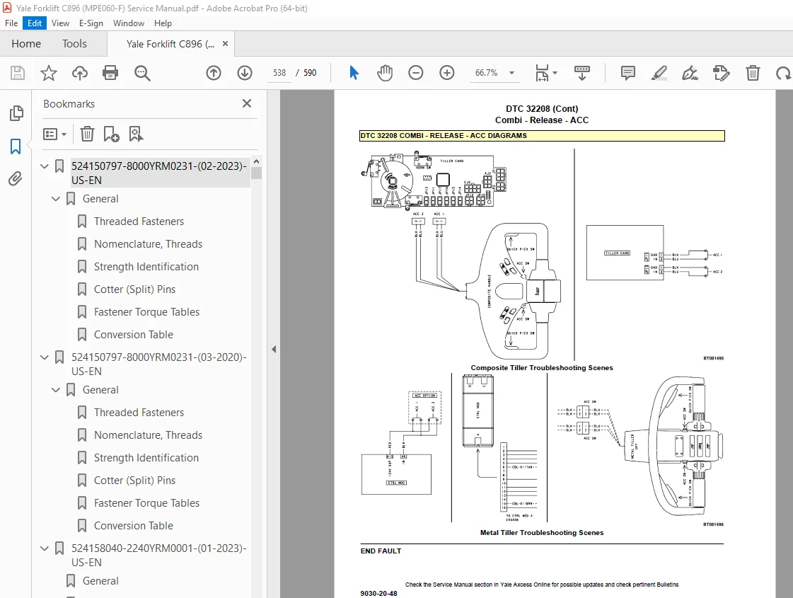
Group 20 – Diagnostic Trouble Codes 491
550142686-0620YRM2005-(12-2018)-US-EN 557
General 561
Accessing the Drive Unit Compartment 561
Unit Codes: C896, D896, E896 561
Unit Codes: B894, B897, B891, D820, D819, D821, D902 562
Special Precautions 563
Discharging the Capacitors 563
Description 564
AC Motor Repair 564
Remove 564
Install 565
Troubleshooting 566
550142687-0630YRM2006-(12-2019)-US-EN 571
Safety Precautions 575
General 577
Check Oil Level 577
Drive Tire 578
Remove 578
Install 578
Master Drive Unit, Kordel® Before December, 2019 578
Remove 578
Disassemble 580
Bevel Gear Set (Ring and Pinion) 580
Remove 580
Install 582
Flange Shaft Seal 582
Remove 582
Install 583
Steering Bearing 583
Remove 583
Replace 583
Master Drive Unit, Kordel® After December, 2019 583
Remove 583
Disassemble 585
Seal Ring 585
Helical Pinion 585
Steering Bearing 586
Assemble 587
Steering Bearing 587
Helical Pinion 587
Seal Ring 587
Install 587
Troubleshooting 588
S.V 06/24