Yale Forklift D815 (NR035EA, NR040EA, NDR030EA) Service Manual PDF
$36.95
Yale Forklift D815 (NR035EA, NR040EA, NDR030EA) Service Manual – PDF DOWNLOAD
Description
Yale Forklift D815 (NR035EA, NR040EA, NDR030EA) Service Manual – PDF DOWNLOAD
FILE DETAILS:
Yale Forklift D815 (NR035EA, NR040EA, NDR030EA) Service Manual – PDF DOWNLOAD
Language : English
Pages : 1268
Downloadable : Yes
File Type : PDF
IMAGES PREVIEW OF THE MANUAL:
TABLE OF CONTENTS:
Yale Forklift D815 (NR035EA, NR040EA, NDR030EA) Service Manual – PDF DOWNLOAD
524150797-8000YRM0231-(02-2023)-US-EN 1
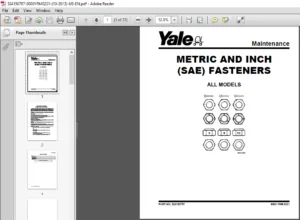
General 7
Threaded Fasteners 7
Nomenclature, Threads 7
Strength Identification 8
Cotter (Split) Pins 9
Fastener Torque Tables 14
Conversion Table 16
524150797-8000YRM0231-(03-2020)-US-EN 23
General 27
Threaded Fasteners 27
Nomenclature, Threads 27
Strength Identification 28
Cotter (Split) Pins 29
Fastener Torque Tables 34
Conversion Table 36
524158040-2240YRM0001-(01-2023)-US-EN 43
General 49
Battery Type 49
Lead-Acid Batteries 49
Lithium-Ion Batteries 50
Specific Gravity 50
Chemical Reaction in a Cell 50
Electrical Terms 52
Battery Selection 53
Battery Voltage 54
Battery as a Counterweight 54
Battery Ratings 54
Kilowatt-Hours 54
Battery Maintenance 55
Safety Procedures 55
Maintenance Records 55
New Battery 55
Cleaning Battery 56
Adding Water to Battery 58
Hydrometer 58
Battery Temperature 59
Charging Battery 60
Types of Battery Charges 61
Methods of Charging 62
Troubleshooting Charger 63
Knowing When Battery Is Fully Charged 63
Where to Charge Batteries 63
Equipment Needed 63
Battery Connectors 64
Battery Care 64
Troubleshooting 66
524158040-2240YRM0001-(03-2020)-US-EN 71
General 75
Battery Type 75
Lead-Acid Batteries 75
Lithium-Ion Batteries 76
Specific Gravity 76
Chemical Reaction in a Cell 76
Electrical Terms 78
Battery Selection 78
Battery Voltage 79
Battery as a Counterweight 80
Battery Ratings 80
Kilowatt-Hours 80
Battery Maintenance 80
Safety Procedures 80
Maintenance Records 81
New Battery 81
Cleaning Battery 81
Adding Water to Battery 83
Hydrometer 84
Battery Temperature 85
Charging Battery 86
Types of Battery Charges 86
Methods of Charging 88
Troubleshooting Charger 88
Knowing When Battery Is Fully Charged 89
Where to Charge Batteries 89
Equipment Needed 89
Battery Connectors 90
Battery Care 90
Troubleshooting 92
524164473-4000YRM0481-(08-2016)-US-EN 97
General 101
Description 101
Lowering Control Valve 102
Main Cylinder Repair 103
Disassemble 104
Assemble 105
Free-Lift Cylinder Repair 106
Disassemble 106
Assemble 106
Troubleshooting 108
524166250-0630YRM1022-(08-2009)-US-EN 111
toc 111
Master Drive Unit 111
Safety Precautions Maintenance and Repair 112
HFK400 Master Drive Unit 115
General 115
Description 115
Drive Unit Maintenance and Repair 116
Remove 116
Install 117
Disassemble 117
Assemble 121
Troubleshooting 129
GK Master Drive Unit 131
General 131
Description 131
Maintenance 132
Changing the Oil 132
Traction Motor and Drive Unit Splines 132
Remove 132
Assemble 133
Mounting Electric Motor 134
Pivoted Connection – Geared Steering 134
Disassemble 135
Install 135
Troubleshooting 136
tables 111
Table 1 Tooth Contact Pattern 126
524183085-2200YRM1058-(04-2011)-US-EN 139
toc 139
Troubleshooting and Adjustments Using the AC Controls Program (E 139
Safety Precautions Maintenance and Repair 140
General 143
Computer Requirements 143
Software, Install 143
Language Selection 143
Demo Mode 144
Connect PC to Lift Truck 148
Starting AC Controls Program 150
Lift Truck Control Setup 155
Change Lift Truck Serial Number or Hourmeter 155
Setting Factory Default Values or Changing Lift Truck Parameters 156
Create New Custom Lift Truck Configuration 162
Lift Truck Configuration Properties 165
Import New Lift Truck Configuration From Disk 168
Delete Custom Lift Truck Configuration or Password File 170
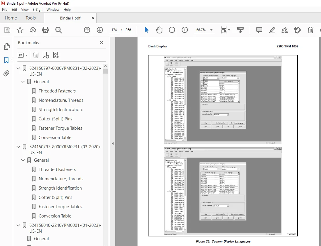
Dash Display 173
Custom Display Languages 173
Download Display Language 175
Clear Operator Log 175
Password Functions 178
Enable/Disable Password and Lift Truck Inspection Functions 178
Truck Inspection Checklist 178
Password 178
Password Properties 178
Create New Password File 183
Download Passwords 184
Upload Passwords 186
Reports Menu 188
Devices Report 188
Custom Report 188
Password Report 188
Operator Report 195
Current Settings Report 198
Status Code Report 202
Status Codes Log 205
Troubleshooting 207
Diagnostics 207
Help Menu 210
General 210
Contents 210
Technical Support 210
About Electric Truck AC Controls Program 210
524223769-2200YRM1128-(01-2023)-US-EN 217
Series Code / Model Designation Reference Table 225
General 227
Deutsch Crimping Tool 228
How to Strip a Wire for Use With Deutsch Crimping Tool 228
How to Crimp With the Deutsch Crimping Tool 229
Calibration Test for the Deutsch Crimping Tool 231
Deutsch Connectors 233
DT, DTM, and DTP Series Connectors 233
HD Series Connectors 276
Metri-Pack Connectors 298
Remove and Install 298
Micro-Pack Connectors 301
Weather-Pack Connectors 302
AMPSEAL Crimping Tools 304
AMP Hand Crimping Tool With Certi-Crimp 304
Description 304
Stripping Wire for Use with AMP Hand Crimping Tool 305
Insulation Crimp Adjustment 306
Maintenance and Inspection for AMP Hand Crimping Tool 306
AMP Hand Crimping Tool 306
Crimp Height Inspection 306
How to use AMP Hand Crimping Tool 307
AMP Pro-Crimper II Tool 307
Description 307
Remove and Install Die Set and Locator Assembly 308
Stripping Wire for Use With AMP PRO-CRIMPER II Tool 308
Contact Support Adjustment 309
Crimp Height Adjustment 310
Maintenance and Inspection Procedures 310
PRO-CRIMPER II Tool 310
Crimp Height Inspection 310
How to Use AMP PRO-CRIMPER II Tool 311
AMPSEAL Connector Assemblies 312
Description for Plug Connector Assembly 312
Seal Plug 313
Contact Crimping 313
Description for Plug Connector and Header Assembly 318
Voltage Reading 321
Seal Plug 321
Contact Crimping 321
AMP Superseal 1 5 Crimping Tools 328
Mini Mic Receptacle and Tab Contacts 328
Description 328
Crimping Conditions and Measurements 328
Insertion of Rubber Seal on Cable 330
AMP Hand Application Tool 335
Description 335
Maintenance and Inspection 335
Crimp Height Inspection 335
Crimp Height Adjustment 336
How to Use AMP Hand Application Tool 336
AMP Pro-Crimper II Tool 337
Description 337
Remove and Install Die Set and Locator Assembly 337
Adjustments 338
Contact Support 338
Crimp Height 339
Inspections and Maintenance 340
Crimp Height Inspection 340
Visual Inspection 340
Maintenance 341
How to Use Pro-Crimper II Tool 341
AMP Superseal 1 5 Connector Assemblies 342
Description 342
Repair and Maintenance 349
Panel Mount Option 349
AMP Fastin-Faston Hand Tools 350
Description – AMP Double Action Hand Tool 350
Maintenance and Inspection Procedures 350
Daily Maintenance 350
Periodic Tool Inspection 351
Lubrication 351
Visual Inspection 351
Crimp Height Inspection 351
Certi-Crimp Ratchet Inspection 352
How to Use AMP Double Action Hand Tool 353
Description – AMP Extraction Tool 354
Maintenance and Inspection 355
How to Use AMP Extraction Tool 355
AMP Fastin-Faston Receptacles and Housings 357
Description 357
Wire Repair 365
Wire Splicing Requirements 365
Deutsch Jiffy Splice 366
Twisted/Shielded Cable and Leads Repair 372
Special Tools 374
524223769-2200YRM1128-(07-2020)-US-EN 383
Series Code / Model Designation Reference Table 389
General 392
Deutsch Crimping Tool 392
How to Strip a Wire for Use With Deutsch Crimping Tool 392
How to Crimp With the Deutsch Crimping Tool 393
Calibration Test for the Deutsch Crimping Tool 395
Deutsch Connectors 397
DT, DTM, and DTP Series Connectors 397
HD Series Connectors 439
Metri-Pack Connectors 462
Remove and Install 462
Micro-Pack Connectors 464
Weather-Pack Connectors 465
AMPSEAL Crimping Tools 467
AMP Hand Crimping Tool With Certi-Crimp 467
Description 467
Stripping Wire for Use with AMP Hand Crimping Tool 467
Insulation Crimp Adjustment 468
Maintenance and Inspection for AMP Hand Crimping Tool 468
AMP Hand Crimping Tool 468
Crimp Height Inspection 468
How to use AMP Hand Crimping Tool 469
AMP Pro-Crimper II Tool 469
Description 469
Remove and Install Die Set and Locator Assembly 470
Stripping Wire for Use With AMP PRO-CRIMPER II Tool 471
Contact Support Adjustment 471
Crimp Height Adjustment 472
Maintenance and Inspection Procedures 472
PRO-CRIMPER II Tool 472
Crimp Height Inspection 472
How to Use AMP PRO-CRIMPER II Tool 473
AMPSEAL Connector Assemblies 474
Description for Plug Connector Assembly 474
Seal Plug 475
Contact Crimping 475
Description for Plug Connector and Header Assembly 480
Voltage Reading 482
Seal Plug 482
Contact Crimping 482
AMP Superseal 1 5 Crimping Tools 489
Mini Mic Receptacle and Tab Contacts 489
Description 489
Crimping Conditions and Measurements 489
Insertion of Rubber Seal on Cable 491
AMP Hand Application Tool 496
Description 496
Maintenance and Inspection 496
Crimp Height Inspection 496
Crimp Height Adjustment 497
How to Use AMP Hand Application Tool 497
AMP Pro-Crimper II Tool 498
Description 498
Remove and Install Die Set and Locator Assembly 499
Adjustments 499
Contact Support 499
Crimp Height 500
Inspections and Maintenance 501
Crimp Height Inspection 501
Visual Inspection 501
Maintenance 502
How to Use Pro-Crimper II Tool 502
AMP Superseal 1 5 Connector Assemblies 503
Description 503
Repair and Maintenance 510
Panel Mount Option 510
AMP Fastin-Faston Hand Tools 511
Description – AMP Double Action Hand Tool 511
Maintenance and Inspection Procedures 511
Daily Maintenance 511
Periodic Tool Inspection 512
Lubrication 512
Visual Inspection 512
Crimp Height Inspection 512
Certi-Crimp Ratchet Inspection 513
How to Use AMP Double Action Hand Tool 514
Description – AMP Extraction Tool 515
Maintenance and Inspection 515
How to Use AMP Extraction Tool 516
AMP Fastin-Faston Receptacles and Housings 517
Description 517
Wire Repair 524
Wire Splicing Requirements 524
Deutsch Jiffy Splice 525
Twisted/Shielded Cable and Leads Repair 530
Special Tools 533
524233332-1600YRM1187-(09-2009)-US-EN 541
toc 541
Steering System 541
Safety Precautions Maintenance and Repair 542
General 545
Discharging the Capacitors 546
Raising the Lift Truck 547
How to Raise the Drive Tire End 547
How to Raise the Entire Lift Truck 548
Description 548
Steering Handle Assembly 551
Fixed Handle 551
Description 551
Remove 551
Disassemble 553
Assemble 555
Install 555
Adjustable Handle 556
Description 556
Remove 556
Disassemble 556
Assemble 560
Install 560
Steering Controller 561
Description 561
Remove 561
Disassemble 561
Assemble 562
Install 562
Steering Proximity Switch 562
Replace 562
Steering Motor 563
Description 563
Remove 563
Disassemble 564
Assemble 564
Install 564
Caster Assembly – General 565
Caster Adjustment 565
Elastomer Spring Type Adjustment 565
Belleville Spring Type Adjustment 566
Spring Pack Replacement 568
Remove Spring Assembly 568
Replace Spring Pack 569
Install Spring Assembly 569
Caster Wheels 570
Remove 570
Install 570
Caster Wheel Assembly (Nonsteered) 571
Description 571
Remove 572
Disassemble 573
Upper and Lower Support Housings 573
Spring Assembly From Lower Support Assembly 573
Caster Spindle From Lower Support 573
Caster Wheels 574
Lower Support Housing 574
Upper Support Housing 575
Assemble 576
Upper Support Housing 576
Lower Support Housing 577
Caster Wheels 577
Caster Spindle to Lower Support 578
Spring Assembly to Lower Support 578
Upper and Lower Support Housings 578
Install 578
Caster Assembly (Steered) 580
Description 580
Remove 580
Disassemble 582
Upper and Lower Support 582
Spring Assembly From Lower Support Housing 582
Caster Spindle From Lower Support 582
Caster Wheels 583
Lower Support Housing 584
Upper Support Housing 585
Caster Steering Motor 585
Assemble 586
Caster Steering Motor 586
Upper Support Housing 586
Lower Support Housing 587
Caster Wheels 588
Caster Spindle to Lower Support 588
Spring Assembly to Lower Support 589
Upper and Lower Support Housings 589
Install 590
Troubleshooting 591
tables 541
Table 1 Caster Specifications 566
Table 2 Upper Adjustment Gap Measurement 568
524233333-0100YRM1185-(03-2011)-US-EN 595
toc 595
Frame 595
Safety Precautions Maintenance and Repair 596
General 599
Description 599
Repairs – General 600
Covers, Panels, and Plates 600
Front Frame Panel (Left and Right) 600
Operator Compartment Cover 601
Drive Unit Compartment Door 601
Door Pad 601
Operator Back Pad 601
Side-Stance Models 601
Forward-Stance Models 601
Operator Front Pad 602
Caster Wheel Cover 602
Load Wheels 602
Remove 602
Install 602
Overhead Guard Replacement 603
Remove 607
Install 607
Front Lights 607
Bulb Replacement 607
Assembly Replacement 608
Rear Work and Caution Light 609
Caution Light 609
Painting Instructions 610
Safety Labels Replacement 611
524233334-0620YRM1186-(08-2009)-US-EN 617
toc 617
AC Motor Repair 617
Safety Precautions Maintenance and Repair 618
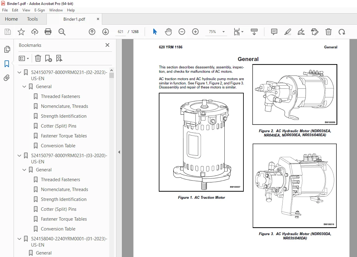
General 621
Traction Motor Repair 622
Disassemble 622
Inspect 623
Assemble 623
Drive End Bearing, Replace 624
Hydraulic Motor Repair 625
Disassemble 625
Inspect 627
Assemble 628
Troubleshooting 629
tables 617
Table 1 Traction Motor Windings 623
Table 2 Hydraulic Motor Windings 628
524233335-1800YRM1188-(01-2016)-US-EN 633
Introduction 637
General 637
Discharging the Capacitors 637
Electric Brake 638
Air Gap 639
Remove 640
Install 641
Troubleshooting 642
524233336-1900YRM1189-(09-2010)-US-EN 647
toc 647
Hydraulic System 647
Safety Precautions Maintenance and Repair 648
General 651
Discharging the Capacitors 653
Description 653
Control Handle 654
Sidestance Control Handle 654
Fore/Aft Stance 655
Maintenance 656
Oil Level and Leaks 656
Operation 656
Oil Change 656
Drain 656
Cylinder Identification 658
Fill 659
Main Lift Cylinders 659
Free-Lift Cylinders 660
Breather Cap 660
Inspect 660
Oil Filter 661
Change 661
Oil Strainer 661
Check 661
Hydraulic System 662
General 662
Cleaning 662
Noise Levels 662
Hoses 662
Fittings 664
Lift Pump and Motor 665
Complete Unit 665
Remove 665
Install 666
Lift Pump 668
Components 668
Pressure Flange Fitting 668
Supply and Return Fittings 669
Manual Lowering Valve 669
Pressure Test Ports 670
Pressure Transducer 670
Relief Valve 672
Lowering Control Valve 673
Remove Pump 673
Install Pump 673
Auxiliary Hydraulics 674
Auxiliary Pump and Motor 674
Remove 674
Disassemble 675
Assemble 676
Install 676
Front Selector Valve 677
Rear Selector Valve 678
Hydraulic Tank 679
Remove 679
Disassemble 680
Breather Assembly 680
Filter Assembly 682
Low Oil Indicator Switch 683
Tank Fittings 684
Clean and Inspect 684
Assemble 684
Breather Assembly 684
Filter Assembly 684
Low Oil Indicator Switch 684
Tank Fittings 684
Install 685
Specifications 686
Troubleshooting 686
tables 647
Table 1 Main Lift Pump and Motor Configurations 653
Table 2 Cylinder Identification 659
524233337-2200YRM1190-(10-2010)-US-EN 691
toc 691
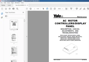
AC Motor Controllers/Display Panel 691
Safety Precautions Maintenance and Repair 692
Description 695
General 695
AC Motors 695
Motor Controllers 695
Master Controller 696
Dash Display 696
Controller Area Network Bus (CANbus) 696
AC Transistor Motor Controller Replacement 697
General 697
General Maintenance Instructions 698
Special Precautions 699
Fuses 699
Fan 700
Contactors 700
Repair 700
Master Controller Checks and Adjustments 701
Function Settings 701
General 701
Troubleshooting 703
General 703
Controller Status Light Emitting Diodes (LEDs) 704
Master Controller 704
AC Motor Controllers 704
Operator Status Messages 707
Status Codes 710
Checking the Motor Controller 782
Display Panel 782
General 782
Premium Display Panel 782
Standard Display Panel 782
Standard Display Functions and Features 784
Key-On Initialization 784
Passwords 784
Performance Modes 785
Battery Discharge Indicator (BDI) 785
Hourmeters 785
Standard Dash Display Service Menu Navigation 786
General 786
Moving Through Menu Selections 786
Editing and Adding Information 786
Access to Service Functions 787
Service Functions 787
Premium Display Functions and Features 789
Key-On Initialization 789
Passwords 789
Operator Checklist Function 789
Performance Modes 789
Battery Discharge Indicator 790
Hourmeters 790
Shelf Height Selector 790
Premium Dash Display Service Menu Navigation 791
General 791
Moving Through Menu Selections 791
Access to Service Functions 792
Service Functions 792
Connector Pin-Outs 794
System Logic Diagram 801
tables 691
Table 1 Factory Parameter Defaults 701
Table 2 Traction Parameter Defaults 702
Table 3 List of Operator Warning Messages 707
Table 4 List of Fault Messages 711
Table 5 Password Prompt Screen 784
Table 6 Password Reminder Screen 784
Table 7 Password Prompt Screen 786
Table 8 Password Prompt Screen 787
Table 9 Password Prompt Screen 789
Table 10 Password Screen 789
Table 11 Password Prompt Screen 791
Table 12 Password Prompt Screen 792
524233338-2200YRM1191-(11-2008)-US-EN 805
toc 805
Electrical System 805
Safety Precautions Maintenance and Repair 806
General 811
Discharging the Capacitors 812
Static Strap 812
Inspect 812
Replace 812
Battery Connection 813
Inspect 813
Replacing Cables 813
Key Switch 814
Replace 814
Contactors 816
Function 816
Testing 817
Remove 817
Install 818
EE Contactors 818
Motor Controllers 819
Functions 819
Master Controller 819
Steering Motor Controller 819
Traction Motor Controller 819
Lift Motor Controller 819
Steer Caster Controller (Optional) 819
Replace 819
Traction and Lift Motor Controllers 820
Master Controller 820
Steering Controller 820
Steer Caster Controller (Option) 821
Integrated Fuse Board (IFB) 821
Fuses 822
Replace 822
Power Disconnect Switch 823
Replace 823
Side-Stance Controls 824
Multifunction Control Handle 824
Remove 825
Disassemble 825
Assemble 827
Install 827
Forward-Stance Controls 828
Control Handle Functions 828
Repair 828
Aft Travel Control Handle Option 830
Repair 831
Steering Handle 832
Steering Unit Repair 832
Foot Switches 836
Brake Switch 836
Operator Sensing 836
Repair 836
Dash Display Assembly 837
Description 837
Remove 838
Test 839
Install 839
Horn 840
Audible Alarm 840
Light Assemblies 841
Front Lights 841
Bulb Replacement 841
Assembly Replacement 841
Rear Work and Caution Light 842
Rear Work Light 842
Caution Light 842
Light Switches 843
Cooling Fans 845
Electrical Compartment Fans 845
Replace 845
Operator Fan 847
Repair 847
Impact Sensor 849
Remove 849
Install 849
Height Proximity Switch 850
Test 850
Remove 850
Install 851
Adjust 851
Load Transport Proximity Switch 852
Replace 852
Adjust 853
Fork Height Sensor Option 853
Remove 853
Encoder Assembly 853
Timing Belt 854
Install 855
Encoder Assembly 855
Timing Belt 856
Reach Position Sensor 856
Remove 856
Install 858
Retract Sensor 859
Remove 859
Install 859
Tilt Leveling 861
Remove 861
Install 861
Laser Option 862
Remove 862
Install 862
Camera Option 863
Remove 863
Install 863
Wiring Harness 863
524233339-2200YRM1192-(11-2012)-US-EN 871
toc 871
User Interface 871
Safety Precautions Maintenance and Repair 872
General 875
Description 875
Dash Display Menu Access 875
Menu Navigation 876
Standard Display 876
Main Menu 876
Diagnostics Menu 877
Static Diagnostics 877
Traction System 881
Hydraulic System 882
Steer System 885
Error Log 886
View Hourmeters 886
View Software Versions 886
Master Controller 886
Display 887
Traction Controller 887
Hydraulic Controller 888
Control Handle 888
Remote CAN Module ( NDR035EA, NR045EA, NDR030EA, NR035/040EA ) 889
Steer Controller 889
Caster Controller 890
Aux Pump ( NDR035EA, NR045EA, NDR030EA, NR035/040EA ) 890
Impact Sensor 890
Functions 892
Impact Action 892
Impact Sound 892
Clear Impact 892
Hard Duration 892
Hard Acceleration 892
Soft Duration 892
Soft Acceleration 893
Impact Events 893
Passwords Menu 893
Add Password 894
Delete Password 895
Edit Password 896
tables 871
Table 1 Static Diagnostics Menu 877
Table 2 Traction System Diagnostics Menu 881
Table 3 Hydraulic System Diagnostics Menu 882
Table 4 Steering System Diagnostics Menu 885
Table 5 Error Log 886
Table 6 Master Controller Software Version 886
Table 7 Display Software Version 887
Table 8 Traction Controller Software Version 887
Table 9 Hydraulic Controller Software Version 888
Table 10 Control Handle Software Version 888
Table 11 Remote CAN Module Software Version 889
Table 12 Steer Controller Software Version 889
Table 13 Caster Controller Software Version 890
Table 14 Aux Pump Controller Software Version 890
Table 15 Impact Sensor Data Display 891
524233340-2200YRM1193-(11-2012)-US-EN 899
toc 899
User Interface 899
Safety Precautions Maintenance and Repair 900
General 903
Description 903
Dash Display Menu Access 903
Menu Navigation 904
Standard Display 904
Main Menu 904
Diagnostics Menu 904
Static Diagnostics 904
Traction System 908
Hydraulic System 909
Steer System 912
General Truck 913
Error Log 914
View Hourmeters 914
Truck Hours 914
Traction Hours 915
Pump Hours 915
Auxiliary Hours 916
Setup Menu 916
Lift Settings 916
Lift Maximum Speed ( NDR035EA, NR045EA, NDR030EA, NR035/040EA ) 916
Lower Maximum Speed ( NDR035EA, NR045EA, NDR030EA, NR035/040EA ) 917
Auxiliary Settings 917
Fast Extend Speed 917
Slow Extend Speed 918
Fast Retract Speed 918
Slow Retract Speed 919
Tilt Up Speed 919
Tilt Down Speed 920
Sideshift Speed 920
Reach Cushioning 921
Steer Settings 921
Steer Mode 921
Steer Effort 922
Steer Ratio 922
Truck Settings 923
Truck Serial Number 923
Truck Voltage 923
Truck Capacity 924
Battery Type 924
BDI Adjust 925
Extended Shift 925
Lift Limit Without Override ( NDR035EA, NR045EA, NDR030EA, NR035 926
Lift Limit With Override ( NDR035EA, NR045EA, NDR030EA, NR035/04 926
Audible Alarm 927
Visible Alarm 928
Autotilt Option 928
Laser Option 929
Carry Level Option 929
Slow Extended 930
Simultaneous Hydraulics 930
Password Option 931
Shutdown Timeout 931
Traction Settings 932
Rabbit Speed 932
Rabbit Acceleration 932
High Speed 933
High Acceleration 933
Mid Speed 934
Mid Acceleration 934
Turtle Speed 935
Turtle Acceleration 935
Neutral Braking 936
Plug Braking 936
View Software Versions 937
Master Controller 937
Display 937
Traction Controller 938
Hydraulic Controller 938
Control Handle 939
Remote CAN Module ( NDR035EA, NR045EA, NDR030EA, NR035/040EA ) 939
Steer Controller 940
Caster Controller 940
Aux Pump ( NDR035EA, NR045EA, NDR030EA, NR035/040EA ) 941
Impact Sensor 942
Functions 942
Functions 943
Impact Action 943
Impact Sound 943
Clear Impact 943
Hard Duration 943
Hard Acceleration 943
Soft Duration 943
Sort Acceleration 943
Impact Events 943
Password Menu 944
Add Password 945
Delete Password 946
Edit Password 947
tables 899
Table 1 Password Screen 903
Table 2 Static Diagnostics Menu 905
Table 3 Traction System Diagnostics Menu 908
Table 4 Hydraulic System Diagnostics Menu 909
Table 5 Steering System Diagnostics Menu 912
Table 6 General Truck Diagnostics Menu 913
Table 7 Error Log 914
Table 8 Truck Hours 914
Table 9 Traction Hours 915
Table 10 Pump Hours 915
Table 11 Auxiliary Hours 916
Table 12 Lift Maximum Speed Menu 916
Table 13 Lower Maximum Speed Menu 917
Table 14 Fast Extend Speed Menu 917
Table 15 Slow Extend Speed Menu 918
Table 16 Fast Retract Speed Menu 918
Table 17 Slow Retract Speed Menu 919
Table 18 Tilt Up Speed Menu 919
Table 19 Tilt Down Speed Menu 920
Table 20 Sideshift Speed Menu 920
Table 21 Cushioning Speed Menu 921
Table 22 Steer Mode Menu 921
Table 23 Steer Effort Menu 922
Table 24 Steer Ratio Menu 922
Table 25 Truck Serial Number Menu 923
Table 26 Truck Voltage Menu 923
Table 27 Truck Capacity Menu 924
Table 28 Truck Type Menu 924
Table 29 BDI Adjust Menu 925
Table 30 Extended Shift Menu 925
Table 31 Lift Limit Without Override 926
Table 32 Lift Limit With Override 926
Table 33 Audible Alarm Menu 927
Table 34 Visible Alarm Menu 928
Table 35 Autotilt Option Menu 928
Table 36 Laser Option 929
Table 37 Carry Level Option Menu 929
Table 38 Restore Defaults Menu 930
Table 39 Simultaneous Hydraulics Menu 930
Table 40 Password Option Menu 931
Table 41 Shutdown Timeout Menu 931
Table 42 Rabbit Speed Menu 932
Table 43 Rabbit Acceleration Menu 932
Table 44 High Speed Menu 933
Table 45 High Acceleration Menu 933
Table 46 Mid Speed Menu 934
Table 47 Mid Acceleration Menu 934
Table 48 Turtle Speed Menu 935
Table 49 Turtle Acceleration Menu 935
Table 50 Neutral Braking Menu 936
Table 51 Plug Braking Menu 936
Table 52 Master Controller Software Version 937
Table 53 Display Software Version 937
Table 54 Traction Controller Software Version 938
Table 55 Hydraulic Controller Software Version 938
Table 56 Control Handle Software Version 939
Table 57 Remote CAN Module Software Version 939
Table 58 Steer Controller Software Version 940
Table 59 Caster Controller Software Version 940
Table 60 Aux Pump Controller Software Version 941
Table 61 Impact Sensor Data Display 942
524233341-4000YRM1194-(01-2016)-US-EN 951
General 955
Safety Procedures When Working Near Mast 956
Mast Weldments 958
Reach Carriage Assembly 958
Three-Stage Mast 960
Description 960
Operation 961
524233342-4000YRM1195-(07-2019)-US-EN 965
General 969
Safety Procedures When Working Near Mast 969
Load Backrest 970
Remove 970
Install 970
Forks 970
Remove 971
Install 971
Checks, Lift Truck Models NR045EA, NDR035EA (C861); NR035EA, NR040EA, NDR030EA (D815); NR035DA, NR040DA, NDR030DA (A295) 971
Checks, Lift Truck Models NR045EB, NDR035EB (D861); NR035EB, NR040EB, NDR030EB (E815); NR035DB, NR040DB, NDR030DB (B295) 972
Sheaves 974
Hydraulic System 977
Hydraulic Oil 979
Drain 979
Cylinder Identification 981
Fill 982
Main Lift Cylinders 983
Free-Lift Cylinders 983
Reach Carriage Assembly 984
Remove 984
Install 986
Load Rollers 987
Mast 987
Reach Assembly 989
Load Rollers 989
Side Rollers 989
Mast 990
Remove 990
Disassemble 991
Clean and Inspect 992
Assemble 993
Install 995
Lift Cylinders 996
Main Lift Cylinders 996
Remove 996
Install 999
Free-Lift Cylinder 1000
Remove 1000
Install 1001
Lift Chains 1002
Clean and Inspect 1002
Mast Adjustments 1003
General 1003
Mast Back Angle Adjustment 1003
Load Rollers Adjustment 1004
Reach Carriage Assembly 1004
Adjust Wear Plugs – Mast 1005
Adjust Main-Lift Chains 1007
Adjust Free-Lift Chain 1007
Adjust Wear Strips 1009
Mast Racking 1010
Proximity Switches 1011
Replace 1012
Free-Lift Proximity Switch 1012
Load Lowering Proximity Switch (Optional) 1013
Adjust 1013
Mast Operation Check 1013
Lift System Leak Check 1014
Lift Cylinder Leak Check 1014
Tilt Cylinder Leak Check 1014
524233343-4500YRM1196-(01-2016)-US-EN 1017
General 1021
Safety Procedures When Working Near Mast 1021
Description 1022
Repair – General 1024
Load Backrest 1024
Remove 1024
Install 1024
Forks 1025
Replacement 1025
Remove 1025
Install 1025
Reach Carriage Assembly 1026
Remove 1026
Inspect 1027
Install 1028
Reach Carriage Assembly Repair 1028
Load Rollers Repair 1029
Side Rollers Repair (6 9 Mast Only) (NDR030DA and NR035/040DA) 1030
Reach Assembly Front Frame 1031
Remove 1031
Disassemble (With Sideshift) 1032
Disassemble (Without Sideshift) 1034
Clean and Inspect 1035
Assemble (With Sideshift) 1035
Assemble (Without Sideshift) 1035
Install 1036
Single-Reach Scissor Arms 1036
Remove and Disassemble 1036
Clean and Inspect 1040
Assemble and Install 1040
Double-Reach Scissor Arms 1042
Disassemble 1042
Clean and Inspect 1046
Assemble 1046
Rear Frame Assembly 1049
Remove 1049
Disassemble 1051
Clean and Inspect 1052
Assemble 1052
Install 1052
Reach Cylinders 1054
Remove 1054
Disassemble 1055
Clean and Inspect 1056
Assemble 1056
Install 1057
Tilt Cylinder 1057
Remove 1057
Clean, Inspect, and Repair 1058
Install 1059
Sideshift Cylinder 1059
Repair 1059
Front Selector Valve 1060
Rear Selector Valve 1061
Reach Assembly Adjustments 1061
Check Adjustment 1062
Adjust Side Rollers and Load Rollers 1063
Adjust Reach Cylinders 1064
Lift Chains 1065
Inspect 1065
Clean and Lubricate 1066
Adjust Main-Lift Chains 1066
Adjust Free-Lift Chains 1066
Specifications 1067
Troubleshooting 1070
524233344-8000YRM1197-(08-2009)-US-EN 1075
toc 1075
Periodic Maintenance 1075
Safety Precautions Maintenance and Repair 1076
General 1079
Removing Covers 1079
Front Frame Panel (Left and Right) 1079
Operator Compartment Cover 1080
Drive Unit Compartment Door 1081
Caster Wheel Cover 1081
Discharging the Capacitors 1081
How to Move Disabled Truck 1082
How to Tow Lift Truck 1082
How to Put Lift Truck on Blocks 1083
How to Raise Load Wheels 1083
How to Raise the Drive Tire End 1084
How to Raise the Entire Lift Truck 1084
Manual Lowering Valve 1084
NDR030/035EA and NR030/040/045EA 1084
NDR030DA and NR035/040DA 1085
Transporting 1086
Loading 1086
Unloading 1086
Preparation for Use 1087
Preparation After Shipment 1087
Preparation After Storage 1087
Safety Procedures When Working Near Mast 1087
Maintenance Schedule 1088
Maintenance Procedures Every 8 Hours or Daily 1093
Checks With Key Switch Turned OFF 1093
Battery 1093
Tires and Wheels 1094
Frame and Load Wheels 1094
Safety Labels 1094
Overhead Guard 1095
Forks Check 1095
Lift Chain Check 1096
Mast Check 1097
Reach, Tilt, and Sideshift 1097
Checks With Key Switch Turned ON 1097
Operation 1097
Hydraulic System 1098
Dash Display 1098
Lift System Operation 1099
Multifunction Control Handle 1100
Brake 1100
Steering System 1100
Maintenance Procedures Every 500 Hours or 3 Months 1101
Master Drive Unit 1101
Hydraulic System 1101
Hydraulic Filter Element Change 1103
Caster Adjustment 1103
Elastomer Spring Type Adjustment 1103
Belleville Spring Type Adjustment 1105
Spring Pack Replacement 1106
Remove Spring Assembly 1106
Replace Spring Pack 1107
Install Spring Assembly 1107
Drive Tire Check 1107
Lift System Operation 1108
Forks 1108
Mast 1108
Lift Chains 1108
Other Lubrication 1108
Maintenance Procedures Every 2000 Hours or Yearly 1109
Brakes 1109
Check 1109
Electric System 1109
Main Contactor 1109
Inspect 1109
Master Drive Unit 1110
Hydraulic System 1110
Drain 1110
Cylinder Identification 1111
Fill 1113
Main Lift Cylinders 1113
Free-Lift Cylinders 1114
Hydraulic Filter Change 1115
Check Hydraulic Strainer 1115
Lift and Tilt System Leaks Check 1116
Lift System 1116
Tilt System 1116
Battery Maintenance 1117
How to Charge Battery 1117
How to Change Battery 1118
Tires and Wheels 1120
Drive Tire 1120
How to Change Drive Tire 1121
Tandem Load Wheels 1122
Caster Wheels 1122
Remove 1122
Install 1123
Preparation for Storage 1124
Short-Term Storage (1 to 6 months) 1124
Long-Term Storage (6 months or longer) 1124
tables 1075
Table 1 Maintenance Schedule 1089
Table 2 Fork Tip Alignment 1095
Table 3 Hydraulic Tank Capacities 1102
Table 4 Caster Specifications 1104
Table 5 Upper Adjustment Gap Measurement 1106
Table 6 Free-Lift Cylinder Rod Widths 1113
Table 7 Battery Size Specifications 1120
Table 8 Tires and Wheels 1121
524233345-8000YRM1198-(05-2008)-US-EN 1127
toc 1127
Capacities and Specifications 1127
Safety Precautions Maintenance and Repair 1128
Lubrication Specifications 1131
Oil Capacities 1131
Hydraulic System 1132
Lift Specifications 1133
Tire Sizes 1138
Torque Specifications 1138
Master Drive Unit 1138
Reach Carriage 1138
Mast 1138
Hydraulic System ( NDR030/035EA and NR030/040/045EA ) 1139
Hydraulic System ( NDR030DA and NR035/040DA ) 1139
Steering System 1139
Load Wheels 1139
Fuses 1139
Coil Resistance Values 1140
Battery Specifications 1141
524233346-8000YRM1199-(12-2013)-US-EN 1145
524260263-2200YRM1240-(11-2008)-US-EN 1209
toc 1209
User Interface 1209
Safety Precautions Maintenance and Repair 1210
General 1213
Description 1213
Dash Display Menu Access 1213
Menu Navigation 1214
Main Menu 1214
Diagnostics Menu 1214
Static Diagnostics 1214
Traction System 1216
Hydraulic System 1216
Steer System 1217
Error Log 1218
View Hourmeters 1219
Truck 1219
Traction 1219
Pump 1219
Auxiliary 1219
Setup Menu 1220
Display Settings 1220
Display Language 1220
Year, Month, Date, Hour, Minute, and Second 1220
View Software Versions 1220
Master Controller 1220
Display 1221
Traction Controller 1221
Hydraulic Controller 1221
Control Handle 1221
Remote CAN Module ( NDR035EA, NR045EA, NDR030EA, NR035/040EA Onl 1221
Steer Controller 1221
Caster Controller 1221
Aux Pump 1221
Passwords Menu 1222
View Operator Log 1222
Add Password 1224
Delete Password 1225
Edit Password 1226
Setup Shelf Height 1227
Learn Shelf Height 1227
Impact Sensor 1228
Functions 1229
Impact Action 1229
Impact Sound 1229
Clear Impact 1229
Hard Duration 1229
Hard Acceleration 1229
Soft Duration 1229
Soft Acceleration 1230
Impact Events 1230
Maintenance Reminder 1230
Functions 1230
Maintenance Reminder 1230
Maintenance Interval 1230
tables 1209
Table 1 Enter Password Screen 1213
Table 2 Static Diagnostics Menu 1215
Table 3 Traction System Menu 1216
Table 4 Hydraulic System Menu 1216
Table 5 Steer System Menu 1217
Table 6 Impact Sensor Data Display 1228
524260264-2200YRM1241-(11-2008)-US-EN 1233
toc 1233
User Interface 1233
Safety Precautions Maintenance and Repair 1234
General 1239
Description 1239
Dash Display Menu Access 1239
Menu Navigation 1240
Main Menu 1240
Diagnostics Menu 1240
Static Diagnostics 1240
Traction System 1242
Hydraulic System 1242
Steer System 1243
General Truck 1244
Height Sensor 1244
Calibrate Fork Tare Down 1244
Calibrate Fork Tare Up 1244
Calibrate Cushion Inpoint ( NDR035EA, NR045EA, NDR030EA, NR035/0 1245
Calibrate Cushion Outpoint ( NDR035EA, NR045EA, NDR030EA, NR035/ 1245
Calibrate Mast Slowdown 1245
Error Log 1245
View Hourmeters 1246
Truck 1246
Traction 1246
Pump 1246
Auxiliary 1246
Setup Menu 1247
Lift Settings 1248
Lift Maximum Speed ( NDR035EA, NR045EA, NDR030EA, NR035/040EA ) 1248
Lower Maximum Speed ( NDR035EA, NR045EA, NDR030EA, NR035/040EA ) 1248
Lift Acceleration 1248
Auxiliary Settings 1249
Fast Extend Speed 1249
Slow Extend Speed 1249
Fast Retract Speed 1249
Slow Retract Speed 1250
Tilt Up Speed 1250
Tilt Down Speed 1250
Sideshift Speed 1250
Reach Cushioning 1250
Steer Settings 1250
Steer Mode 1251
Steer Effort 1251
Steer Ratio 1251
Display Settings 1251
Display Language 1251
Year, Month, Date, Hour, Minute, and Second 1251
Truck Settings 1252
Serial Number 1252
Voltage 1252
Capacity Lbs 1252
Battery Type 1252
BDI Adjust Calibration 1252
Extended Shift 1253
Shelf Height Selection 1253
Load Weight Option ( NDR035EA, NR045EA, NDR030EA, NR035/040EA ) 1253
Lift Limit Without Override ( NDR035EA, NR045EA, NDR030EA, NR035 1253
Lift Limit With Override 1253
Audible Alarm 1253
Visible Alarm Option 1253
Fork Height Display 1254
Auto Tilt Option 1254
Laser Option 1254
Carry Level Option 1254
Slow Extended 1254
Simultaneous Hydraulics 1254
Password Option 1254
Shutdown Timeout 1254
Truck Inspection 1254
Traction Settings 1254
Rabbit Speed 1254
Rabbit Acceleration 1255
High Speed 1255
High Acceleration 1255
Mid Speed 1255
Mid Acceleration 1255
Turtle Speed 1255
Turtle Acceleration 1255
Neutral Braking 1256
Plug Braking 1256
View Software Versions 1256
Master Controller 1256
Display 1256
Traction Controller 1256
Hydraulic Controller 1256
Control Handle 1257
Remote CAN Module ( NDR035EA, NR045EA, NDR030EA, NR035/040EA ) 1257
Steer Controller 1257
Caster Controller 1257
Aux Pump 1257
Passwords Menu 1257
Functions 1258
View Operator Log 1258
Add Password 1258
Delete Password 1260
Edit Password 1260
Setup Shelf Height 1261
Learn Shelf Height 1262
Impact Sensor 1262
Functions 1264
Impact Action 1264
Impact Sound 1264
Clear Impact 1264
Hard Duration 1264
Hard Acceleration 1264
Soft Duration 1264
Soft Acceleration 1264
Impact Events 1264
Maintenance Reminder 1265
Functions 1265
Maintenance Reminder 1265
Maintenance Interval 1265
tables 1233
Table 1 Enter Password Screen 1239
Table 2 Static Diagnostics Menu 1241
Table 3 Traction System Menu 1242
Table 4 Hydraulic System Menu 1242
Table 5 Steer System Menu 1243
Table 6 General Truck Menu 1244
Table 7 Impact Sensor Data Display 1263
S.V 05/24