Yale Forklift D847 (MS12X – MS14X – MS16X – MS20X) Service Manual PDF
$29.95
Yale Forklift D847 (MS12X – MS14X – MS16X – MS20X) Service Manual – PDF DOWNLOAD
Description
Yale Forklift D847 (MS12X – MS14X – MS16X – MS20X) Service Manual – PDF DOWNLOAD
FILE DETAILS:
Yale Forklift D847 (MS12X – MS14X – MS16X – MS20X) Service Manual – PDF DOWNLOAD
Language : English
Pages : 460
Downloadable : Yes
File Type : PDF
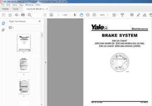
PART NO. 550208134
IMAGES PREVIEW OF THE MANUAL:
TABLE OF CONTENTS:
Yale Forklift D847 (MS12X – MS14X – MS16X – MS20X) Service Manual – PDF DOWNLOAD
550208134-0100YRM2203-(10-2019)-UK-EN 1
Important 5
General safety rules 6
Torque settings for screws nuts and fittings 10
Correct method for applying female fittings 12
Instructions for installing flexible hoses and fittings 14
Truck presentation 15
Views of the truck 16
Truck and load identification data 18
General specification 22
Truck wheel 42
Removal of the traction wheel 43
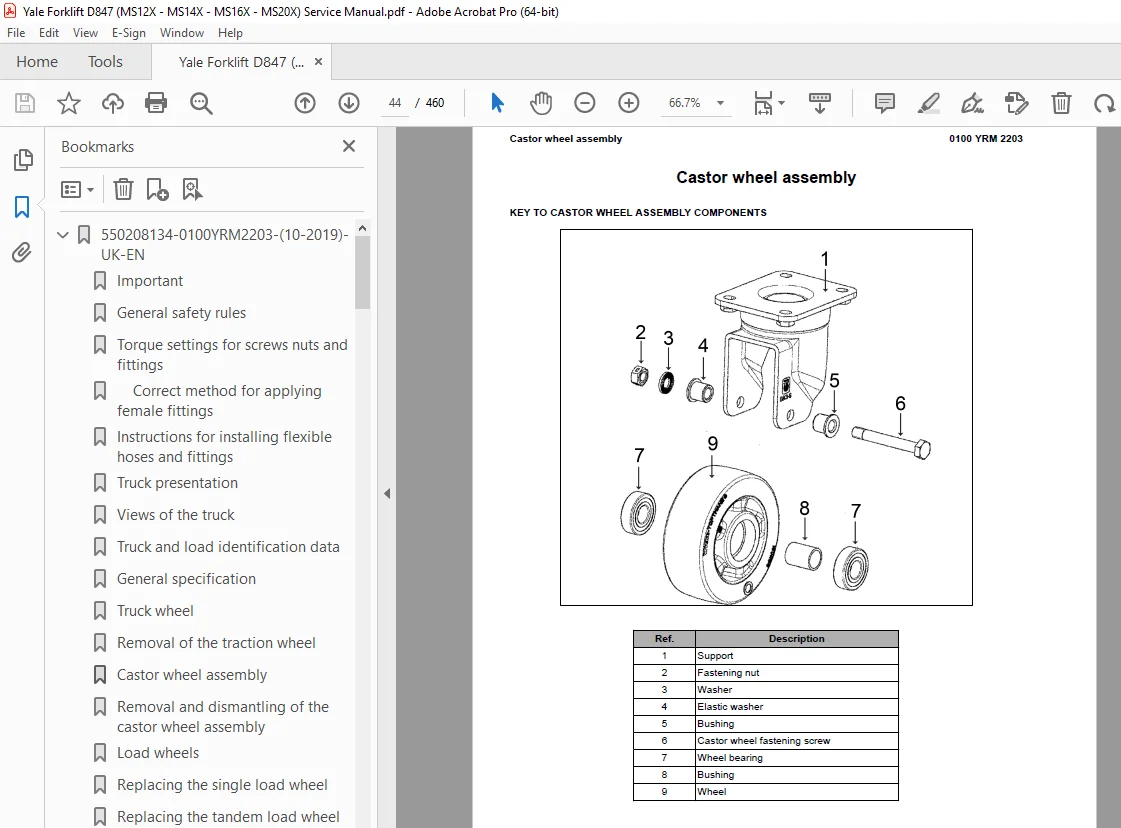
Castor wheel assembly 44
Removal and dismantling of the castor wheel assembly 47
Load wheels 49
Replacing the single load wheel 53
Replacing the tandem load wheel 55
Replacing the tandem load wheel assembly 56
Replacing the single – tandem load wheel assembly 58
Linkage assembly 59
Removal of the linkage assembly 60
Adjustment of the tie rod assembly 62
Support device 63
Support device replacement 64
Straddle legs 65
Key to tiller components 68
Tiller spring replacement 72
Tiller removal 74
Replacement of the potentiometer and tiller base bearings 75
Removal of the platform gas spring 77
Replacement of the platform potentiometer 78
Side gate replacement 79
Side gates microswitch replacement 80
Traction motor 82
Key to electric steering unit components 85
Motor dismantling 88
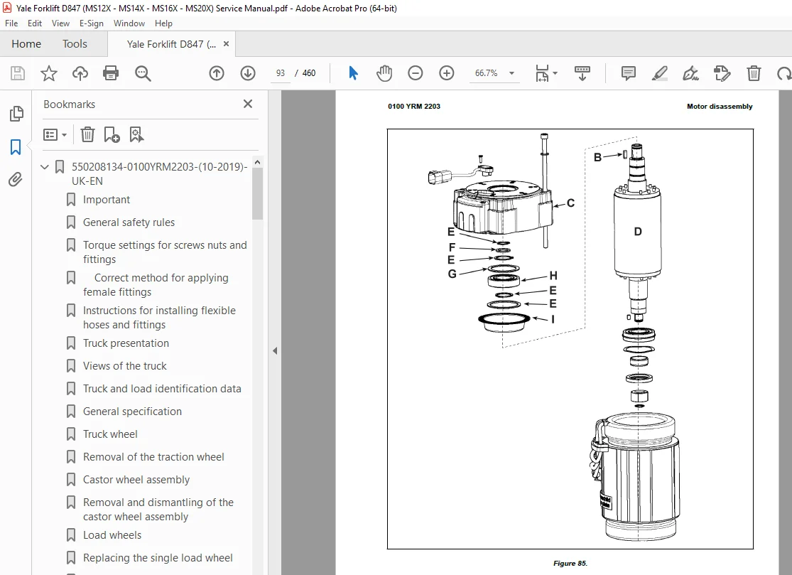
Motor disassembly 90
Electric steering motor dismantling 94
Replacement of the controller 96
CDF file loading procedure 98
550208139-8000YRM2204-(10-2019)-UK-EN 101
Before Installation 106
Machine assembly 109
Topping up the oil reservoir 111
Installation of the battery with vertical extraction 112
Installation of the battery with side extraction 114
Side installation of battery without rollerway 116
Installation of battery with side removal 118
Connection of cables to battery 120
List and description of the settings and adjustments to be carried out 121
550208144-8000YRM2205-(09-2019)-UK-EN 123
Description of module connectors 128
Tester menu 130
Troubleshooting 139
Diagnosis system for Combi Module 140
Diagnosis system for EPS-BLI 165
Electrical component measurements 177
550208149-2200YRM2206-(10-2019)-UK-EN 181
Wiring diagrams 186
Electrical components 232
Key to tiller controls and main panel 237
MDI Display 241
Truck functions 243
Electric steering 255
Procedure for access to configuration parameters 257
Combi Module 258
Description of the Combi module parameters 260
EPS – BLI module 265
Description of the EPS-BLI module parameters 266
Module introduction 267
Combi AC0 Module 268
EPS-BLI Module 270
Replacement of the controller 271
CDF file loading procedure 273
Charge curve uploading procedure 275
Replacement of the general emergency switch 279
Replacement of the display 281
Replacement of the key switch 283
Replacement of the keypad (optional) 285
Replacement of the horn 287
Replacement of the fuses 288
Replacement of the power fuse 289
Replacement of the horn relay 290
Replacement of the main contactor switch 291
Replacement of the battery charger (optional) 292
Replacement of the back-up alarm 294
Replacement of the tiller sensor 295
Replacement of the tiller board 297
Replacement of tiller buttons 299
Replacement of tiller control springs 301
Position of mast sensors 302
Replacement of sensors assembly 305
Replacement of the centred wheel sensor 309
Platform acquisition 309
550208154-1900YRM2207-(10-2019)-UK-EN 313
Hydraulic functions 317
Hydraulic diagrams 320
Hydraulic diagrams for various functions 327
Hydraulic components 351
Dismantling of cartridge soilenoid valves 352
Dismantling the throttle 357
Dismantling the balancer 358
Cylinders 359
Dismantling of lateral lift cylinder 365
Dismantling of central lift cylinder 372
Removal of the “Initial Lift” cylinder 376
Lifting cylinder air bleeding 378
Replacement of static gaskets on lateral lift cylinders 379
Replacement of static gaskets on the central lift cylinder 381
Lift pump 384
Lift pump dismantling 386
Pump replacement 389
Hydraulic pipes 391
Cylinder supply pipe replacement 396
Central cylinder supply pipe replacement 400
550208159-4000YRM2208-(10-2019)-UK-EN 405
Mast characteristics 409
Mast assembly components 412
Dismantling the complete column 415
Dismantling the inner mast stage 417
Dismantling the intermediate mast 419
Replacement of chains and chain tensioner 421
Replacement of the side cylinders chain sheaves 423
Fork small mast 425
Removal of the fork small mast 426
Replacement of the fork small mast chains and chain tensioners 429
Replacement of the small mast chain sliding sheave 431
Fem Fork Carriage 432
Fem fork replacement 433
550208164-0630YRM2209-(09-2019)-UK-EN 435
Identification of the master drive unit 439
Removal and disassembly of the reduction unit 441
Braking System 443
Removal of the electromagnetic brake 445
Electromagnetic brake adjustment 446
550208169-8000YRM2210-(09-2019)-UK-EN 449
Maintenance Warnings 453
Oils and Lubricants 454
Cleaning products 454
Scheduled Maintenance 455
S.V 05/24